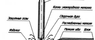
A T-joint in welding represents the letter “T” and is used in the creation of metal structures where components must touch at right angles. The area of such contact, as a rule, becomes not very large, so it is necessary to structurally strengthen the products and weld the joint on several sides, so a T-joint can have one seam or two.
Such connections have good strength, but if a high level of load is planned for this area, then you should make sure that the second end of the part extending perpendicularly from the main part is also welded to the base. This will help secure everything and avoid deformation.
The following classes are distinguished:
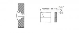
- Weld seam T1 according to GOST 5264 80 refers to the classification of welded joints that are made using manual arc welding;
- According to GOST 14771-76, seams that were made using shielding gas welding are classified;
- GOST 14806-80 includes connections without beveled edges, which were also created in protective gases.
When welding a T-joint of thin metal to thicker metal, it is necessary that the angle of inclination of the electrode or welding torch be about 60° to the thicker metal.
Welding a T-joint (and a corner joint to the same extent) can be greatly simplified by positioning it for welding “in a boat”. This allows welding to be carried out predominantly in the down position, increasing welding speed and reducing the likelihood of undercuts, which are a very common defect in T-weld joints, along with lack of fusion. In some cases, one pass will not be enough, so oscillation of the torch is required for filling joints.
The edges of the joined parts can be cut depending on the thickness of the parts being welded and the number of seams:
- metal thickness up to 4 mm, single seam - no edge treatment;
- thickness from 4 mm to 8 mm - without edge treatment, double seam;
- from 4 mm to 12 mm - single seam with groove on one side;
- from 12 mm, the edge is cut off on both sides, and two seams are also made.
Advantages of a T-joint
- Allows you to provide connections in hard-to-reach places that would not be possible by other means;
- It is possible to scald the contact area on both sides, which will increase strength;
- Can be used to connect both thick and thin parts;
- There is no need to use additional pads, since if there is a reliable fixation, the seam can be simply butted;
- The structure can withstand quite heavy loads after treatment with such compounds.
Advantages and disadvantages
Butt weld joints have the following number of advantages over other methods of assembling metal elements into one structure.
- This welding technology is not critical to the thickness of the parts being welded. The thickness can vary from fractions to hundreds of millimeters. This criterion does not depend on the welding method and is determined only by the possibility of butt joining the material.
- A butt weld requires less filler materials and energy resources, therefore reducing the cost of the connection.
- Unlike other types of joining parts, welding practically does not increase the overall weight of the structure, the seam is smooth and sealed, and quality control of the connecting weld is simplified.
Flaws
- The difficulty of making the connection, since the part to be welded must be fixed before welding (if this is not done reliably enough, the geometry of the structure will be disrupted);
- When welding a part on one side, the connection is not very reliable, since the impact on the opposite side acts as a lever for breaking the seam;
- Very thin parts become difficult to weld due to inconvenience and a high risk of deformation, especially when welding on both sides;
- A small contact area does not always ensure a reliable connection;
- When used in the professional field, an accurate preliminary calculation of the T-weld joint is always required so that breakdowns do not occur during operation.
Design requirements for welded joints
To ensure high quality and reliable operation of welded joints, they must meet a number of requirements dictated by the possibility and convenience of welding, possible reduction of welding stresses and deformations, full operation of welds in various types of joints, etc. All these requirements must be taken into account when designing metal designs.
The seams must have the smallest leg and be made strictly according to calculation. The leg of butt welds is dictated by the thickness of the elements being connected and is assumed to be equal to the smaller of them (at different thicknesses).
The smallest leg of fillet welds is 4 mm, further gradation is 5, 6, 7, 8, 10 mm and then after 2 mm. Fillet welds with a thickness of more than 20 mm have large internal stresses and are not recommended for use.
The leg of fillet welds is determined by calculation.
The largest leg of a fillet weld, depending on the thickness of the elements being joined, can be taken = 1.2t (t is the smallest thickness of the elements being welded).
The edges of rolled profiles are rounded on one side, so the largest leg of the fillet weld along these edges is taken to be slightly smaller than the thickness of the profile leg or flange. The largest leg of a fillet weld along the edge of the corner can reach 1.2 t (t is the thickness of the corner flange).
When manual welding, a seam with a leg of up to 8 mm can be made in one pass. In cross section, fillet welds must have a weld leg ratio of 1:1. To reduce stress concentrations in structures that perceive dynamic and vibration loads or under static loads, but are operated with a design temperature below –40°C, as well as in any structures made of high-strength steels in frontal fillet welds, the leg ratio is taken to be 1:1.5, with the larger leg must be directed along the force perceived by the connection.
The minimum design length of a fillet weld should be no less than 40 mm due to the presence of lack of fusion at the beginning and end of the weld.
The maximum design length of flank fillet welds should be no more than , since in fact the stress in the seam is distributed unevenly along its length, then with very long seams its extreme points can be overstressed, and the middle part is not fully included in the work.
This limitation does not apply to those flank seams in which forces are transmitted along the entire length of the seam, for example, to the belt seams of welded beams.
The structural length of the seam, i.e. the length indicated on the drawings is taken to be approximately 10 mm greater than the estimated length (determined by calculation), since the beginning and end of the seam may have lack of fusion and a crater, therefore sections of 5 mm at the ends of the seam should not be taken into account in the calculation.
If the design uses intermittent seams, then to ensure reliable joint operation of the connected elements, the distance between the sections of the seams in the clear should be no more than 15t in compressed elements and no more than 30t in stretched and non-working elements (t is the smallest thickness of the connected elements).
The overlap in lap joints must be at least 5t of the thinnest element being joined, otherwise cracks may form in the seams caused by welding deformations.
When butt-joining sheets of different thicknesses, if the difference in the thicknesses of steels exceeds 4 mm and the size of the ledge does not exceed 1/8 of the thickness of the thinner sheet, the joint can be made without bevel of the edges for steels (for stronger ones, 2 mm and 1/12, respectively).
Otherwise, for a smooth transition of forces at the joint, a one-sided or two-sided bevel of the edges with a slope of no more than 1/5 is required.
Avoid crossing welds, placing them close to each other, and forming closed contours with seams.
Standards for welded joints and seams and rules for certification of welders
The list of standards establishing, depending on the welding (soldering) method, the type of product being welded or the metal of the product, the main types of welded joints, structural elements and dimensions, is presented in Table. 1.
Table 1. Areas of application of GOST for the main types of seams and welded joints, structural elements and dimensions
| GOST _____________ | Name | Distribution area |
| 5264-80 | Manual arc welding. Welded connections. Main types, structural elements and dimensions | Connections made of steels, as well as alloys based on iron-nickel and nickel bases. The standard does not apply to welded joints of steel pipelines in accordance with GOST 16037-80 |
| 8713-79 | Submerged arc welding. Welded connections. Main types, structural elements and dimensions | Connections made of steels, as well as alloys based on iron-nickel and nickel bases. The standard does not apply to welded joints of steel pipelines in accordance with GOST 16037-80 |
| 11533-75 | Automatic and semi-automatic submerged arc welding. Welded connections at acute and obtuse angles. Main types, structural elements and dimensions | Connections made of carbon and low alloy steels |
| 11534-75 | Manual arc welding. Welded connections at acute and obtuse angles. Main types, structural elements and dimensions | Connections made of carbon and low-alloy steels made by manual arc welding with a consumable electrode in all spatial positions with a thickness of the welded metal up to 60 mm inclusive |
| 14098-91 | Welded connections of reinforcement and embedded products of reinforced concrete structures. Types, design and dimensions | Reinforcement connections and embedded products made by resistance and arc welding from rod and wire reinforcing steel with a diameter of 3 to 40 mm, as well as sheet and shaped rolled products in the manufacture of reinforced concrete products and the construction of monolithic and prefabricated reinforced concrete structures |
| 14771-76 | Gas shielded arc welding. Welded connections. Main types, structural elements and dimensions | Steel connections. The standard does not apply to welded pipe joints |
| 14776-79 | Arc welding. Point connections. Main types, structural elements and dimensions | Point connections made of steels, copper, aluminum and nickel alloys |
| 14806-80 | Arc welding of aluminum and aluminum alloys in inert gases. Welded connections. Main types, structural elements and dimensions | Connections made of aluminum and aluminum deformable thermally non-hardening alloys with edge thicknesses of welded parts from 0.8 to 60 mm inclusive |
| 15164-78 | Electroslag welding. Welded connections. Main types, structural elements and dimensions | Steel connections. The standard does not specify the size of the gap between the parts to be welded before welding |
| 15878-79 | Contact welding. Welded connections. Structural elements and dimensions | Connections made of steels, alloys on iron-nickel and nickel bases, titanium, aluminum, magnesium and copper alloys, made by resistance spot, relief and seam welding. The standard does not apply to welded joints made by contact welding without melting the metal. |
| 16037-80 | Welded connections of steel pipelines. Main types, structural elements and dimensions | Steel pipeline connections. The standard establishes the main types, structural elements and dimensions of welded joints between pipes and pipes and fittings. The standard does not apply to welded joints used for the manufacture of pipes from sheet and strip metal |
| 16038-80 | Arc welding. Welded connections for pipelines made of copper and copper-nickel alloy. Main types, structural elements and dimensions | Connections of pipes with pipes made of copper grades M1r, M2r, M3r in accordance with GOST 859-2001 and copper-nickel alloy grade MNZh 5-1, with flanges made of brass grade L90 and with fittings and nipples made of bronze grades BrAMts9-2 or BrAZhNmts 9-4-4 -1. The standard does not apply to welded joints used for the manufacture of pipes from sheet or strip metal |
| 16098-80 | Welded connections made of two-layer corrosion-resistant steel. Main types, structural elements and dimensions | Connections made of double-layer corrosion-resistant steel |
| 19249-73 | Soldered connections. Basic types and parameters | Soldered connections, structural elements of soldered seams, their designations and parameters |
| 23518-79 | Gas shielded arc welding. Welded connections at acute and obtuse angles. Main types, structural elements and dimensions | Connections made of steels and alloys on iron-nickel and nickel bases |
The specified standards for various metal thicknesses regulate: the type of connection, the shape and dimensions of the prepared edges, the nature of the weld, the shape and structural elements of the cross section of the weld, the symbol of the welded joint.
The standards determine not only the structural elements of prepared edges and possible deviations of their main dimensions, but also regulate the sizes of seams and maximum deviations of their parameters. For example, GOST 5264-80 defines for each type of weld a symbol, the maximum thickness of the welded products s, the size and maximum deviations of the gap b, the width of the seam e, the convexity of the seam g, its maximum deviations, etc. The same parameters are determined by GOST 8713-79 , 14771-76, 14776-79, 14806-80, 16037-80, 16038-80, 16098-80, and GOST 16037-80 and 16038-80, in addition, regulate the maximum deviations in the wall thickness of welded pipes.
Butt welding of joints of parts of unequal thickness with a difference not exceeding the values indicated in the table. 2, is produced in the same way as for parts of the same thickness. The structural elements of the prepared edges and the dimensions of the seam should be selected according to the greater thickness.
If the difference in the thickness of the parts being welded exceeds the values indicated in the table. 2, on parts with a large thickness s1, a bevel should be made on one side or on both sides to the thickness of the thin part s, as shown in Table. 3. In this case, the structural elements of the prepared edges and the dimensions of the weld should be selected based on their smaller thickness.
Table 2. Permissible maximum difference in thicknesses of abutting parts welded without bevel of edges
| GOST | Thickness of thin part, mm | Difference in thickness of parts, mm |
| 5264-80 | 1…4 | 1 |
| 5…20 | 2 | |
| 21…30 | 3 | |
| Over 30 | 4 | |
| 8713-79 | 2…4 | 1 |
| 5…30 | 2 | |
| 31…40 | 4 | |
| More than 40 | 6 | |
| 14771-76 | 2…3 | 1 |
| 4-30 | 2 | |
| 31-40 | 4 | |
| More than 40 | 6 | |
| 16098-80 | 4…7 | 1 |
| 8…20 | 2 | |
| 21…36 | 3 | |
| More than 40 | 4 |
Table 3. Bevel of a part with a large thickness when butt-joining it with a thin-walled part
| GOST ____________ | One-sided bevel | Double bevel |
| 5264-80, 8713-79 | ||
| 14771-76 | ||
| 16098-80 |
When welding butt joints of parts (except for pipes), GOST 5264-80, 8713-79, 14771-76 allow the following displacements of the welded edges relative to each other before welding:
| Part thickness s, mm | Displacement, mm |
| Up to 4 | 0,5 |
| 4…10 | 1 |
| 10…100 | 0.1s, but not more than 3 |
| More than 100 | 0.01s+2, but not more than 4 |
GOST 16098-80 allows displacement of the edges relative to each other before welding up to 10% of the sheet thickness, but not more than half the thickness of the cladding layer and no more than 3 mm when the thickness of the cladding layer is more than 6 mm.
When welding fillet welds, GOST regulates the permissible values of convexity and concavity of welds (Table 4). According to GOST 5264-80, when welding in positions other than the bottom, an increase in convexity is allowed by no more than 1 mm for parts with a thickness of up to 60 mm and by no more than 2 mm for parts with a thickness of more than 60 mm.
Table 4. Acceptable values of convexity and concavity of fillet welds
| GOST ____________ | Seam convexity | Seam concavity |
| 5264-80, 8713-79, 14771-76 | Up to 30% of the leg size, but not more than 3 mm | Up to 30% of the leg size, but not more than 3 mm. In this case, the concavity should not lead to a decrease in the calculated size of the leg |
| 16098-80 | When welding in the lower position, the convexity of the seam should not exceed, mm: 1.5 at K < 5 mm; 2.5 at 5 mm≤K ≤ 10 mm; 3.5 at K > 10 mm; When welding in other spatial positions, an increase in convexity by 1 mm is allowed | Seam concavity no more than 3 mm |
The dimensions of fillet weld legs K and K1 according to GOST 5264-80 and 8713-79 must be established when designing a welded joint, but not more than 3 mm for parts with a thickness of up to 3 mm inclusive and 1.2 times the thickness of a thinner part when welding parts with a thickness of more than 3 mm mm.
The maximum deviations of the dimensions of fillet weld legs K and K1 from the nominal value must correspond, mm:
1 mm - for K and K1 ≤ 5 mm; 2 mm - for K and K1 ≥ 6 mm.
The minimum dimensions of fillet weld legs according to GOST 5264-80 and 8713-79 are given in table. 5.
Table 5. Minimum dimensions, mm, of fillet weld legs for the thickness of the thicker element being welded
| Yield strength of welded steel, MPa | Thickness of the thicker element to be welded, mm | |||||||
| 3…4 | 4…5 | 5…10 | 10…16 | 16…22 | 22…32 | 32…40 | 40…80 | |
| Up to 400 | 3 | 4 | 5 | 6 | 7 | 8 | 9 | 10 |
| 400…450 | 4 | 5 | 6 | 7 | 8 | 9 | 10 | 12 |
Note. The minimum leg size should not exceed 1.2 times the thickness of the thinner element.
GOST 11969-79 establishes the basic provisions of welding and their designations for welds performed by fusion welding in both one and several layers.
GOST 312-72 regulates conventional images and designations of welded joints in technical documentation and drawings. Regardless of the welding method, a visible seam in the drawings is indicated by a solid line, and an invisible one by a dashed line; a visible weld point is indicated by “+”, and an invisible one is not indicated. A leader line is drawn from the image of a line or point, ending with a one-way arrow.
The visible seam symbol is placed above the leader line flange. This GOST regulates other cases of using various symbols, abbreviations, and additional signs describing welds. The current persistent trend of integration of the former USSR countries into Europe forces us to rebuild the level of welding production in accordance with European standards, otherwise the CIS countries will not be competitive in the metal products market.
An important aspect of this activity is the certification of welding personnel as a means of ensuring the quality of welding work, taking into account the actual welding processes used in production. The Regulations on Certification Tests of Welders is a document mandatory for all ministries, departments, associations, organizations, enterprises, legal entities and individuals. It regulates the interaction of certification bodies and determines their competence, the procedure for conducting and processing the results of certification of welders for permission to perform welding work on objects and equipment provided for by the rules of labor protection (safety), safe operation and other regulations approved by the relevant independent government bodies. In Russia, these are Gosgortekhnadzor, Gosatomenergonadzor, and the River and Sea Register.
In Russia, the “Rules for the certification of welders and welding production specialists PB-03-273-99 Gosgortekhnadzor of the Russian Federation” are in force. During certification, theoretical knowledge and practical skills are checked for each specific welding method, the type of work is determined using standard samples for testing, a protocol is drawn up and a welder's certificate is issued, which meets the requirements of the European standard EN 287-1. It specifies the conditions of all tests, certification categories and the scope of certification. Below is an example of a record of approval for manual arc welding of steam and hot water pipelines, pipe elements of boilers, gas pipelines and process pipelines:
111 T BW WO1 B nh t10 D273 PF ss nb, which means: the approval gives the right to weld pipes with a diameter of more than 140 mm and metal structures with a wall thickness from 3 to 20 mm from steels of the first group, which are welded with coated electrodes: basic, rutile, rutile-basic and rutile acid; single-sided butt seams without backing, with backing and double-sided seams, with and without stripping the root of the seam, in the lower (RA), horizontal-vertical (RV), horizontal-ceiling (RD) and vertical (PE) positions.
The developed standards based on the requirements of ISO 9606 make it possible to certify welders in fusion welding of steels, aluminum, titanium, nickel and their alloys, as well as additional types of welding, high-temperature soldering and brazing-welding of metals.
If the certification was carried out under the auspices of a reputable independent organization, such as the Technical Supervision Society TUV (Technische Uberwachung Verein), Germany, then the resulting welder’s certificate is valid for work in 130 countries.
Cutting edges for welding
The weld will be of high quality after carefully carried out preparatory work. They are necessary before welding structures whose element thickness exceeds 5 millimeters. For one-sided welding. The preparatory operation is called edge cutting. The rules and quality of such work are determined by GOST requirements. Removal of contamination from the entire edge should be carried out at a distance of at least 20 millimeters from the future welding site.
Download GOST 5264-80
The main types of this operation are:
- through careful cutting;
- without preliminary cutting;
- the so-called flanging.
Edge preparation and parameters
The flanging is made one-sided for corner joints, double-sided for butt joints.
Preparation is carried out manually (using a file, sandpaper, metal brush) or using electric tools (drills equipped with the necessary attachments, grinders, factory equipment).
For metal with a thickness ranging from 3 mm to 26 mm, a V-shaped single-sided or double-sided type of edge bevel is used. For metal with a thickness of 12 to 60 mm, an X-shaped type of bevel is made.
Edge preparation procedure
A procedure has been established for preparing the material for subsequent work with any type of welded joints. It includes the following items:
- cleaning the edge of the metal (any dirt, deposits, corrosion are removed);
- removing the necessary chamfers (this operation depends on the method used for welding);
- preparation of the gap (size, quality must correspond to a certain type).
Cleaning the edge of the metal