Device performance characteristics:
Dimensions of the main unit: 445 x 180 x 271 mm
Device weight: 5.3 kg. Place of production: Republic of China
Warranty: 12 months
Tool class: For domestic needs Equipment type: Inverter Welding type: (MMA) (coated electrode welding) Power: 5500 W Welding current of the device: DC constant
Phase options: 1 Power source type: mains (220 V) Electrode diameter range: 1.6 - 5 mm Max. possible power: 5000 W Max. mains voltage: 180-240 V Cooling form: forced air Protection class / insulation type: IP 21/H Min. current: 20 A No-load voltage: 75 V Rated frequency: 50 Hz Packaging type: Plastic suitcase
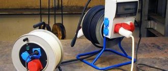
Welding inverter device
Depending on the model, welding inverters operate both from a household electrical network (220 V) and from three-phase (380 V). The only thing that needs to be taken into account when connecting the device to a household network is its power consumption. If it exceeds the capabilities of the electrical wiring, then the unit will not operate if the network is drained.
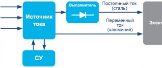
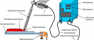
So, the inverter welding machine includes the following main modules.
- Primary rectifier unit. This block, consisting of a diode bridge, is located at the input of the entire electrical circuit of the device. It is this that is supplied with alternating voltage from the mains. To reduce the heating of the rectifier, a heat sink is attached to it. The latter is cooled by a fan (supply fan) installed inside the unit housing. The diode bridge also has overheating protection. It is implemented using a temperature sensor, which breaks the circuit when the diodes reach a temperature of 90°.
- Capacitor filter. It is connected in parallel to the diode bridge to smooth out alternating current ripples and contains 2 capacitors. Each electrolyte has a voltage reserve of at least 400 V, and a capacity of 470 μF for each capacitor.
- Filter for noise suppression. During current conversion processes, electromagnetic interference occurs in the inverter, which can disrupt the operation of other devices connected to this electrical network. To remove interference, a filter is installed in front of the rectifier.
- Inverter. Responsible for converting AC voltage to DC. Converters operating in inverters can be of two types: push-pull half-bridge and full bridge. Below is a diagram of a half-bridge converter with 2 transistor switches, based on devices of the MOSFET or IGBT series, which can most often be seen on inverter devices of the middle price category.
The circuit of a full bridge converter is more complex and already includes 4 transistors. These types of converters are installed on the most powerful welding machines and, accordingly, on the most expensive ones.Just like diodes, transistors are installed on radiators for better heat removal from them. To protect the transistor unit from voltage surges, an RC filter is installed in front of it.
- High frequency transformer. It is installed after the inverter and reduces the high-frequency voltage to 60-70 V. Thanks to the inclusion of a ferrite magnetic core in the design of this module, it is possible to reduce the weight and dimensions of the transformer, as well as reduce power losses and increase the efficiency of the equipment as a whole. For example, the weight of a transformer that has an iron magnetic core and is capable of providing a current of 160 A will be about 18 kg. But a transformer with a ferrite magnetic core with the same current characteristics will have a mass of about 0.3 kg.
- Secondary output rectifier. It consists of a bridge that contains special diodes that respond to high-frequency current at high speed (opening, closing and recovery takes about 50 nanoseconds), which conventional diodes are not capable of. The bridge is equipped with radiators that prevent it from overheating. The rectifier also has protection against voltage surges, implemented in the form of an RC filter. At the output of the module there are two copper terminals, which ensure reliable connection of the power cable and ground cable to them.
- Control board. All operations of the inverter are controlled by a microprocessor, which receives information and controls the operation of the device using various sensors located in almost all components of the unit. Thanks to microprocessor control, ideal current parameters are selected for welding various types of metals. Electronic control also allows you to save energy by supplying precisely calculated and dosed loads.
- Soft start relay. To prevent the rectifier diodes from burning out from the high current of charged capacitors during startup of the inverter, a soft start relay is used.
Advantages of Gerrard MMA-200
The Gerrard MMA-200 Home Line is a new remake of the MMA-200 variant of the same brand. The modernized version is equipped with an electronic dial and a convenient handle for transportation. The engineers also took care of transporting the device by providing it with a special case. Being light in weight, you can easily use Gerrard MMA-200 during installation at height; it does not hinder your movements. If you are the owner of a car repair shop, or you need a welding machine at your summer cottage or garage, this model is perfect. Gerrard MMA-200 is designed for welding, cutting and surfacing of various ferrous and non-ferrous metals. Having a wide range of possible electrodes used, the welder will be able to choose any required diameter up to 5 mm. This model has the first class of protection against electric shock. The device is very quiet in operation, low energy consumption, and excellent value.
gerrard mma 200 reviews
Based on reviews, we have compiled a characteristic of this inverter. Most users, even if they noticed the negative aspects of the product, were generally satisfied with the purchase and did not regret the money spent. In addition, do not forget that among the buyers there are many beginners in the field of welding, who attribute their own operational errors to the inverter. Let's look at the advantages of the device that domestic consumers have noticed:
- good device for little money;
- long-term operation of the device, which is not typical for inverters, reaching up to a whole working day, without overheating;
- small dimensions and weight of gerrard mma 200;
- successful long-term operation;
- - slight sticking of the electrode.
Schematic diagram of a welding inverter
Modern welding work is carried out using special inverters. Previously, conventional transformers, which are characterized by lower efficiency, were used for such metal processing. The schematic diagram of a welding inverter may differ slightly, but they are all characterized by lightness and compactness. Only by taking into account the design features can the welding inverter be repaired and fine-tuned.
Elements of the electrical circuit of welding inverters
The electrical circuit diagram of an inverter welding machine involves a combination of several elements that are interconnected. The main ones can be called:
- The block responsible for supplying energy to the power section. This element is represented by a combination of several devices that are capable of changing current parameters to the required values. Typically, a capacitive filter and a rectifier are included.
- The device includes a power transformer. The power supply of the welding inverter also includes a 4n90 transistor.
- A separate element is responsible for powering the low-current part of the structure.
- To control the main parameters, a PWM controller is installed. It is represented by a combination of a load current sensor and a transformer.
- A separate block is responsible for protecting the structure from heat. When electrical current passes, some components may become very hot. Therefore, an additional cooling module is installed, represented by a fan and a temperature sensor.
- Control units that allow you to set basic parameters, as well as display elements.
Example of circuit diagram for current 250A
The diode bridge equipment for the welding machine is manufactured and installed taking into account the power of the device and some other points. Each device has its own characteristics, which we will consider in detail below.
Common causes of breakdowns
Do-it-yourself repair of welding inverters is possible for the following faults:
- Unstable welding arc. In most cases, such a malfunction is associated with an incorrect choice of the inverter operating mode. To select the optimal current strength, you can follow the rule: 20 to 40 amperes of current should be supplied per 1 millimeter of electrode diameter.
- The appearance of forces when separating the electrode from the metal. A typical malfunction that occurs due to low voltage coming to the electrodes. The simplest way to solve this problem is to clean the contacts of the power supply from oxides and carbon deposits.
- No welding jet. If there is no power when you turn the toggle switch to turn on the device, you should check the voltage in the electrical network.
- Inverter shutdown during prolonged operation. As a rule, such behavior of the inverter can be associated with overheating. The way out is simple: let the device cool down and start working again after 30 minutes.
Scheme of an inverter welding machine.
When diagnosing a welding machine, the following faults may be detected:
- arising as a result of incorrect choice of welding mode;
- arising as a result of failure of electronic components of equipment.
In any of the above cases, you can repair the welding inverter yourself.
Most malfunctions of this welding machine unit are associated with the failure of electronic components.
The main types of electronic circuit faults are presented:
- Moisture entering the inverter housing. Oxidation of conductive paths due to moisture ingress can cause a breakdown in contact between the main components of the device.
- Formation of a large amount of dust on the main working elements. Excessive dust contamination of inverter elements can disrupt the natural circulation of air in the housing and lead to overheating of electronic components.
- Selecting the wrong operating mode for the inverter, resulting in overheating of electronic components. Inverter failure due to overheating of electronic components is one of the most common failures.
In addition, the device’s inoperability may be due to the failure of one of the modules.
Most inverters use:
- input rectifier;
- output rectifier;
- key control unit;
- cooling system.
Swaris device diagrams
The welding machine Svaris 200 is characterized by ease of use and low cost. Already the Swaris 160 models had high performance characteristics, and the new version was improved. The circuit of the inverter welding machine determines the following operational characteristics:
- The maximum consumption is 5 kW.
- Welding current can vary from 20-200 A.
- The open circuit voltage indicator is 62 V.
- Efficiency rate 85%.
- Recommended electrodes 1.6-5.0.
Inverter machines - a new generation of manual welding
Since the beginning of 2000, inverter welding machines have become cheaper and more accessible. To carry out welding work at home, it is enough to have this small and easy-to-use device and good electrodes.
Advantages of inverters
Inverter machines are lightweight, compact in size, and their scope of use and welding quality are higher than those of heavy and bulky welding transformers. They carry out their task in full: they weld cars, gates, pipe structures (for example, greenhouses or gazebos). Working with them is mobile - throwing an extendable belt over your shoulder, welding is carried out in any hard-to-reach places.
When vertical, horizontal or overhead welding, the current is reduced by 10–20%, and when welding at an angle, it is increased by the same amount compared to the normal position.
There are also no problems with the connection; the welding machine operates from a regular electrical network. It's great that it won't stop when the mains voltage drops. If the deviation is within +/- 15%, the device will continue to operate normally. The current value can be adjusted by selecting the power depending on the type and thickness of the metal. All this makes inverters ideal for both beginners and professionals.
Video: testing a homemade inverter device
How welding inverters work
The inverter unit connects parts with direct current using electric arc welding with a coated electrode. The big plus is that at the very beginning of the process there are no power surges in the network to which the device is connected. The storage capacitor ensures uninterrupted electrical circuit and soft ignition of the arc with its further automatic maintenance. When connected to an electrical outlet, the alternating mains voltage with a frequency of 50 Hz is converted first into direct voltage and then into high-frequency modulated voltage. Then, using a high-frequency transformer, the current increases, the voltage decreases, and the output current is rectified. The device provides adjustment of the welding current value and protection against overheating.
The inverter device first rectifies and modulates the input current, and then increases its strength by reducing the voltage until the arc appears
The basic operating mode of inverter welding machines is MMA. This is manual arc welding with piece coating electrodes. For welding steel and cast iron products using direct or alternating current, a diameter of 1.6–5.0 mm is used.
The devices differ in power and operating cycle duration . The second indicator is the period during which it is allowed to cook at the maximum permissible power in order to prevent the device from overheating. It is designated by the letters PV (on period) and is determined as a percentage relative to a time unit of 10 minutes. For example, if the device indicates a PV of 60%, this means that it can be cooked for 6 minutes and then turned off for 4 minutes. Sometimes the welding cycle is set to 5 minutes. Then a PT value of 60% means a work period of 3 and a rest period of 2 minutes. PV and duty cycle indicators are indicated in the instructions for each device.
Schemes of models MMA-200 and MMA-250
The MMA-200 and MMA-250 models are widely used. These inverters are almost identical, the only difference is the following points:
- The MMA 250 welding inverter circuit provides for the presence of 3 field-type resistors in the output stage. All are connected in parallel. The MMA 200 welding inverter circuit indicates only the presence of two resistors.
- The new version has three pulse transformers, while the old one only has two.
The basic design of both models is almost completely identical.
MMA-200 inverter circuit
Inverter 3200 and 4000 circuits
For manual arc welding, you can use the Inverter 4000 or 3200. Both machines have an almost identical design, which provides the following functions:
- Protection against electrode sticking effect.
- Protecting key components from severe voltage surges.
- Control of basic arc parameters.
- Built-in cooling element with control sensors.
During the manufacture of inverters, IP21 protection was provided. The power of the device is 5.3 kW, powered by a standard power supply network. The detailed diagram of inverter 3200 pro determines the very attractive properties of these models, due to which they have become widespread.
Schemes of other models
As previously noted, almost all inverters operate on a similar principle, and the created circuits may differ insignificantly. All welding machines are divided into several main groups:
- To carry out electric arc welding when using electrodes coated with a special composition, MMA type equipment is used. This scheme is characterized by high efficiency, and the design is light in weight.
- To use refractory electrodes, MMA+TIG welding equipment is used. They can operate in an environment of inert gases.
- On production lines there are units with semi-automatic bar feeding. In this case, work is usually carried out in an environment of inert gases or in special baths.
- For forging or other repairs, spot welding is used.
The ARC 160 model, the circuit of which is quite complex, can be used for a wide variety of work. Unlike the arc 140, the new model's circuit has no major drawbacks.
Welding inverter TORUS 250
The Torus 250 version consists of the following elements:
- A clock type generator built on a TL microcircuit. It is worth considering that the powerful inverter circuit does not provide for the use of PWM, but the microcircuit has two comparators with thermal protection sensors.
- The protection system and control module are made on the basis of LM. The sensor that determines the current parameters is placed on a ferrite ring with a winding.
- The circuit also includes two output drivers built on IR
A separate category includes a welding inverter circuit using thyristors, which has become very widespread.
Repair of Torus 250 should be carried out by opening the structure and visually inspecting the main elements. In this case they are as follows:
- The output type rectifier is represented by a separate board on which two radiators are placed. They serve as a base for placing diode assemblies. The module also includes one transformer and a choke. The number of elements in the output rectifier largely depends on the specific assembly.
- The switch module is represented by four transistors in each of the four groups. In order to reduce the degree of heating, they are all placed on separate radiators, which are insulated with special gaskets.
- A powerful diode bridge is used as the output rectifier. In the case under consideration, it is located at the bottom of the structure. This model is equipped with an extremely reliable and practical bridge, which is difficult to burn if the cooling system is working properly.
- The control chip is the main design element. As a rule, the durability of the entire device depends on its correct operation. You can check the unit yourself only if you have a special oscilloscope and the appropriate skills to work with it.
- Housing with cooling fan. As a rule, the cooling unit fails only in the event of mechanical impact.
To diagnose many elements, it is necessary to dismantle them. That is why it is best to entrust the work to professionals, since incorrect assembly can lead to significant problems.
The welding inverter SAI 200, the circuit of which differs insignificantly from devices of a similar type, is used for manual arc welding and surfacing when using stick electrodes. RDMMA 200 belongs to a new type of equipment that is created without the use of transformers. Due to this, more accurate and smooth adjustment of current indicators is possible, and there is no strong noise during operation.
In conclusion, we note that the above information determines the complexity of the design of welding inverters. At the same time, manufacturers do not distribute detailed diagrams of devices, which complicates maintenance and repair. Despite the use of a similar circuit when creating almost all inverters, they differ significantly from each other. That is why, before carrying out any work, you need to familiarize yourself in detail with the design features of the device.
DEVICE AND REPAIR OF WELDING INVERTER
Modern welding machines, in order to reduce size and weight, are built exclusively using an inverter circuit, with powerful field-effect transistors as power switching elements. Despite the many different models of such devices, the essence of the work and the principle of operation are almost the same. This article will be useful for understanding the functioning of inverter circuits, as well as for repairing them yourself. The domestic welding inverter “TORUS” was chosen as an example.
Design of the welding machine “TORUS-200”
“TORUS-200” - an inverter-type welding machine is a direct current source with short-circuit protection and thermal protection. The current source converter is made according to a full-bridge circuit with a conversion frequency of about 100 kHz. The current is adjusted by changing the duty cycle of control pulses at a constant frequency. Four converter keys are located on separate radiators. Each switch consists of four parallel IRFP460 field-effect transistors.
The transformer of the converter is wound with Litz wire in a silk braid directly onto the core, i.e. without frame. A choke is installed nearby, which is connected in series with the primary of the transformer, and both are wound with one piece of wire, i.e. "local". The output rectifier is made according to a push-pull circuit (with the middle output of the secondary winding). Each rectifier arm is mounted on a separate radiator and consists of two 60CPQ150 or four 30CPQ150 diode assemblies. The rectifier, power supply converter consists of a GBPC3508W bridge mounted on a radiator and six parallel electrolytic capacitors 470 uF 400V. Schematic diagram:
The soft switching circuit is a delay relay for switching on the full charge of the capacitors of the converter power supply rectifier. Actuator element – e.m. relay closing a powerful resistor.
The control board contains:
1. Electronics power supply, which is designed as a separate module and is a standard 15V power supply. 2. “Soft switching” scheme. 3. Block of capacitors for the charge-discharge circuit of the converter. 4. Converter control circuit. Also, on the front panel of the device there is a board for indicating, turning off and adjusting the current.
The converter control circuit consists of:
1. Clock generator on the TL494 chip. It produces two phase clock pulses with a frequency of about 100 kHz. PWM functions are not used and the microcircuit produces pulses of constant duty cycle. This microcircuit has two comparators, to which thermal protection sensors are connected (thermistors on the inductor and the output rectifier radiator).
2. Schemes for current regulation and short-circuit protection. Made on two comparators of the LM393 chip. The current sensor is made on a ferrite ring with a winding through which the positive power wire of the converter passes.
3. Two output drivers based on IR2112 chips. The driver inputs receive clock pulses, the duty cycle of which varies in the driver from pulses coming from the comparators of the current regulation and short-circuit protection circuit. The driver outputs are loaded onto pulse transformers, from the secondary windings of which control pulses are supplied to the converter switches.
Recommendations for self-repair of a welding machine
SA "Torus" is produced by several manufacturers. The first such device came across under the name “Duga-200” and at the time of writing this article, seven devices of this design have passed through my hands. I assume that this circuit is also suitable for younger Torus models, since in order to reduce the maximum welding current it is enough to reduce the number of switches in the group and the number of diode assemblies or install weaker components.
To repair a welding machine, like any other electronic device, it is highly desirable to have some knowledge of electronics and at least minimal repair experience. If you have neither one nor the other, but have a lot of desire and money, then you can try. The required instruments are an oscilloscope and a dial avometer. Any repair begins with opening and external inspection of the insides. Structurally, Torus consists of the following modules:
1. Input rectifier module 2. Output rectifier module.. 3. Key control board. 4. Case with fan.
Input rectifier module . The input rectifier is a powerful diode bridge mounted on a radiator, which is attached to the control board from below. The GBPC3508W bridge is extremely reliable and you have to try harder to burn it. Nevertheless, it is not superfluous to check it. Everyone knows how the bridge rings and nothing new can be invented here. For the inexperienced, we can advise you to unsolder the wires from it, so that in case of a short circuit you do not mislead yourself. It is better to immediately remove the radiator with the bridge from the board to make working with it easier in the future.
Key module. The switch module consists of four groups of four transistors per group. Each group is mounted on a separate radiator on an insulating gasket. In addition to the keys, the module includes six electrolytic capacitors for the smoothing filter of the rectifier that powers the converter (input rectifier).
Most often, a faulty transistor is immediately visible: a cracked or broken case, burnt-out terminals, but sometimes there are no external signs of a malfunction, and then a dial avometer should be used to identify the faulty transistor. We turn it on in resistance measurement mode to the Kom x1 limit and select any group. I think it would be useful to remind you that all measurements should be carried out with the device turned off from the network. We measure the resistance between drain and source. For those who do not know the pinout of the IRFP460 transistor: if you position the case with the leads down and the markings facing you, then from left to right there will be a gate, a drain, a source. There is an anti-parallel diode between the drain and the source, and it should ring, i.e. high resistance in one direction, low resistance in the other. A short circuit is a malfunction of one or more transistors in a group, and if there is one, the faulty transistor is detected only by desoldering.
If a group rings as expected (in one direction), this does not always mean that all transistors in the group are working. They need to be checked individually for openability. This can be done without soldering each transistor. First, we unsolder one end of the equalizing resistors from each gate, place the negative probe at the source of the first transistor, and the positive probe at the drain. The tester should show high resistance. Now for a moment we touch the positive probe (without removing the negative one) to the shutter and again transfer it to the drain. The resistance should drop to almost zero and this means that the transistor has opened. Using tweezers or a scalpel, we close the gate with the drain or source and again measure the drain-source resistance, which should increase almost to infinity (but it is more reliable to apply reverse voltage to the gate to turn off the transistor, i.e. minus to the gate, plus to the drain) and this means that the transistor has turned off. If this is the case, we move on to another transistor, otherwise we double-check and bite out the faulty transistor, since this makes it easier to prepare a place for installing a working transistor. If all transistors in the group are operational, solder the ends of the equalizing resistors to the gates, mark the group as operational and move on to the next group. To repair, check and search for possible analogues of radio elements, study their datasheets.
When all transistors have been checked and faulty ones have been replaced with good ones, the key module can be conditionally considered working. Conditionally - this is because the final check will be in the presence of control signals. Recently, switches began to be equipped with snubbers (capacitors soldered between the drain and source of each transistor), which protect the transistors from breakdown. In this case, the efficiency of the device decreases somewhat, but the reliability increases many times over. When testing the transistors, the capacitors do not need to be unsoldered, because they do not affect the measurement results.
Output rectifier module . The output rectifier module consists of a board with two radiators on which power diode assemblies are mounted. Depending on the assemblies used, their number on the radiator may be different - two or four. The module also includes a choke and a transformer. Diode assemblies of the output rectifier rarely fail. The two-hundredth model uses two 60CPQ150 or four 30CPQ150 assemblies, and each assembly has two diodes of 60 and 30 amperes (respectively) of maximum current each. That's a total of 240 amps DC. A reserve of 40 amperes is quite reliable, and the maximum pulse current is almost an order of magnitude greater. Everyone knows how diodes ring. If the group rings short, you need to look for a broken diode. You can't do without desoldering, and for this it is convenient to use a soldering iron with suction. When all diodes have been checked and faulty ones have been replaced, the module can be marked as good and we can begin checking the control board.
The key control board is the most complex of all units of the device, and the reliability of the device and the integrity of its components depend on its correct operation. A preliminary check of the operation of the control board can be done without dismantling it, i.e. right on the spot. First of all, we turn off the power to the converter, for which we unsolder one of the thick wires coming from the control board (220V AC) from the input bridge and insulate its bare end with electrical tape.
Since to assess the performance of the control board it is necessary to evaluate rapidly changing signals, you cannot do without an oscilloscope (and the skill of working with it). We insert the power plug into the socket and listen carefully. The fan rotates and after 3-5 seconds a click is heard. It is produced by the relay of the “soft” switching circuit. If there is no click or it is heard immediately after switching on, then the “soft” switching circuit is faulty. Also, if there is no click, it is worth checking the presence of +15V supply voltage. The source of this power is glued to the control board and soldered to it with four wires: two of which are 220V AC and the other two are plus and minus 15V. If there is no power, we dismantle the power supply and repair or replace it, since it is standard.
The “soft” switching circuit is very simple and is based on the activation of em. relay K2 as a result of the opening of transistor VT5 after charging capacitor C22 in its base circuit. Relay contacts S3 short-circuit resistor R40, which extinguishes the charging current of the input rectifier filter capacitors. This resistor is very weak and often fails. I replace this resistor, even if it is working, with a more powerful one to increase the reliability of the device. The absence of a relay response delay can be caused by a break in the charge capacity C22, a breakdown of the transistor VT5 and a breakdown of the dinistor analogue VD4 in the transistor base circuit.
Next, we check for the presence of key control signals. These signals are sent via four twisted pairs of wires to the gate buses of the key module. We set the oscilloscope sweep to 5 µs/div, and the attenuator to 5 or 2v/div. We connect the common wire of the oscilloscope to the common wire of the control board (occupies a noticeable part of the front side area), and use a probe to check the signals on legs 1 and 7 of the DD2 and DD3 microcircuits. Normally, there should be rectangular pulses with a rounded front with an amplitude of about 15 V and a frequency of about 100 KHz. If there are pulses, you should check their passage to each gate.
If the device has been in someone’s “skillful” hands before, it’s a good idea to check the phasing of the control signals: if the twisted pairs are reversed, then there is a risk of running into a through current, and if the wires in the pair are reversed, the key will not open. I came across devices literally “plowed” by “craftsmen” and these devices had to be checked thoroughly. The situation is further complicated by the fact that the assembly quality of the devices is semi-handicraft and it is not always possible to distinguish the soldering of the manufacturer from the soldering of a “craftsman”.
For those uninformed, I can clarify: the gate should receive positive (relative to the source) pulses with an amplitude of about 15V. At the same time, groups 1 and 4 should open in one measure and 2 and 3 in another measure. Signal in-phase can be determined using a two-channel oscilloscope.
If the control signals from the control board arrive at each gate with the required amplitude and in the required phase, you can try to turn on the device. In order to insure against the consequences of an undetected malfunction, we turn on the power of the converter through a 150-200 W incandescent lamp - it is more convenient to connect it to the alternating circuit of the input rectifier bridge. We solder all the wires that were previously soldered taking into account the lamp and turn on the device into the network and look at the lamp. At the first moment, the lamp may flash brightly (the filter capacities are charging), but it should glow faintly all the time. A bright glow indicates a short circuit in the circuit or load circuit. .When all the faults are eliminated, unsolder the lamp, solder the power wire to the bridge and turn on the device to the network. We measure the voltage at the output terminals - the normal voltage level should be about 60 DC volts.
In the case when the control board does not produce triggering pulses, for ease of operation it is better to separate it from all nodes, i.e. unsolder the twisted pairs from the keys, having previously marked the groups and wires, unsolder the overheating sensors and insulate the ends of the wires, unsolder and disconnect the input bridge rectifier, unsolder the power cord.
Next, solder the power cord, preferably through a 50-100W light bulb, and plug it into a power outlet. First of all, you should check the presence of +15V power on pins 3,6,9 of microcircuits DD2 and DD3 and rectangular clock pulses on pins 10 and 12 of the same microcircuits. A couple of times I encountered the burnout of a resistor in the DD3 power circuit, although after that the microcircuit itself had to be replaced. If there are clock pulses on legs 10 and 12 (i.e., at the inputs), but there are no pulses on legs 1 and 7 (i.e., at the outputs), leg 11 needs to be connected to the common wire, and if the microcircuit is working properly, the pulses at the outputs should to appear. There are no pulses - feel free to replace the microcircuit. In normal condition, leg 11 of microcircuits DD2 and DD3 may not have an exact zero (i.e., the microcircuit is closed) and to check whether the microcircuit is faulty or closed, you need to apply an exact zero to leg 11.
If the driver inputs (DD2 and DD3) do not receive clock pulses, then they need to be looked for at pins 9 and 10 of the PWM chip - DD4. If they are absent, check the +15V power supply at pins 8, 11, 12. You can check whether the red indicator on the front panel of the device is lit, and if so, then the operating mode toggle switch is most likely turned off. You can also check whether one of the two overheating sensors is shorted (on the output rectifier radiator and on the inductor). If all efforts are in vain, we replace the microcircuit.
You have achieved control pulses at the outputs of both drivers. It would seem that this is happiness, but this happiness may be followed by fireworks when you try to light an arc. The fact is that there is also a current regulation and current protection circuit, and if this protection does not work, then you risk going to the second round of troubleshooting.
The adjustment and protection circuit is implemented on the DD1 chip and its wiring. The current sensor is a ring coil L1 through which the thick power wire of the converter passes. At pins 1 and 7 of the DD1 microcircuit, rectangular driver closing pulses are formed. You can check the operation of the circuit in different ways. I use the following: I unsolder one end of the L1 coil and solder a 3V AC voltage source instead. This could be a transformer from a power adapter or something original. I supply 3V variables and watch the signals at pins 1 and 7 of the DD1 microcircuit - short rectangular pulses with a frequency of 50Hz. At the same time, the ring transformers emit quiet sounds (vaguely reminiscent of the voice of a grasshopper), and the triggering pulses are interrupted at a frequency of 50 Hz. Author of the article: V.A. Tretyakov.
Originally posted 2018-10-14 13:32:19. Republished by Blog Post Promoter
Welding inverter "MMA 200", device, repair.
The main element of the simplest welding machine is a transformer operating at a frequency of 50 Hz and having a power of several kW.
Therefore, its weight is tens of kilograms, which is not entirely convenient. welding inverters have become widespread . Their main advantages: small dimensions, smooth adjustment of welding current, overload protection. The weight of a welding inverter with a current of up to 250 Amps is only a few kilograms.
The operating principle of the welding inverter is clear from the block diagram below:
An alternating mains voltage of 220 V is supplied to a transformer-free rectifier and filter (1), which generates a constant voltage of 310 V. This voltage powers a powerful output stage (2). The input of this powerful output stage is supplied with pulses with a frequency of 40-70 kHz from the generator (3). The amplified pulses are supplied to the pulse transformer (4) and then to a powerful rectifier (5) to which the welding terminals are connected. The control and overload protection unit (6) regulates the welding current and protects it.
Since the inverter operates at frequencies of 40-70 kHz and higher, and not at a frequency of 50 Hz, like a conventional welder, the dimensions and weight of its pulse transformer are tens of times smaller than a conventional 50 Hz welding transformer. And the presence of an electronic control circuit allows you to smoothly regulate the welding current and provide effective protection against overloads.
Let's look at a specific example.
The inverter stopped cooking. The fan works, the indicator lights up, but the arc does not appear.
This type of inverter is quite common. This model is called "Gerrard MMA 200 "
We managed to find a diagram of the “MMA 250” inverter, which turned out to be very similar and significantly helped in the repair. Its main difference from the required MMA 200 :
- The output stage has 3 field-effect transistors connected in parallel, while the MMA 200 has 2 each.
- There are 3 output pulse transformers, while the MMA 200 has only 2.
The rest of the scheme is identical.
Briefly about the scheme itself.
At the beginning of the article, a description of the block diagram of a welding inverter is given. From this description it is clear that the welding inverter is a powerful pulsed power supply with an open circuit voltage of about 55 V, which is necessary for the occurrence of a welding arc, as well as an adjustable welding current, in this case, up to 200 A. The pulse generator is made on the U2 microcircuit type SG3525AN, which has two outputs for controlling subsequent amplifiers. The generator U2 itself is controlled through an operational amplifier U1 type CA 3140. This circuit regulates the duty cycle of the generator pulses and thus the output current, which is set by a current control resistor located on the front panel.
From the output of the generator, pulses are sent to a pre-amplifier made of bipolar transistors Q6 - Q9 and field switches Q22 - Q24 operating on transformer T3. This transformer has 4 output windings which, through shapers, supply pulses to 4 arms of the output stage assembled using a bridge circuit. In each shoulder, two or three powerful field workers stand in parallel. In the MMA 200 scheme there are two, in the MMA 250 scheme there are three. In my case, MMA-200 contains two field-effect transistors of type K2837 (2SK2837).
From the output stage, through transformers T5, T6, powerful pulses are supplied to the rectifier. The rectifier consists of two ( MMA 200 ) or three (MMA 250) full-wave rectifier circuits with a midpoint. Their outputs are connected in parallel.
A feedback signal is supplied from the rectifier output through connectors X35 and X26.
Also, the feedback signal from the output stage is fed through current transformer T1 to an overload protection circuit made on thyristor Q3 and transistors Q4 and Q5.
The output stage is powered by a mains voltage rectifier assembled on a VD70 diode bridge, capacitors C77-C79 and generating a voltage of 310 V.
To power low-voltage circuits, a separate switching power supply is used, made on transistors Q25, Q26 and transformer T2. This power supply generates a voltage of +25 V, from which +12 V is additionally generated via U10.
Let's get back to the renovation. After opening the case, a visual inspection revealed a burnt 4.7 uF capacitor at 250 V.
This is one of the capacitors through which the output transformers are connected to the output stage on the field devices.
The capacitor was replaced and the inverter started working. All voltages are normal. A few days later the inverter stopped working again.
Upon detailed inspection, two broken resistors were discovered in the gate circuit of the output transistors. Their nominal value is 6.8 ohms, in fact they are in a break.
All eight output FETs were tested. As mentioned above, they are included two in each arm. Two shoulders, i.e. four field workers are out of order, their terminals are short-circuited. With such a defect, high voltage from the drain circuits enters the gate circuits. Therefore, the input circuits were checked. Faulty elements were also found there. This is a zener diode and a diode in the pulse formation circuit at the inputs of the output transistors.
Welding inverter mma 200 circuit
Good day to all. There is a Svarog Real 200 Arc machine, purchased as a donor for PA welding. I visually tinkered with the diagram. There is a shunt on the minus side. A voltage of 66 mV is removed from it in short-circuit mode with a 4 mm electrode. But there is also a CT on the primary of the power transformer. It gnawed the track that goes to the OS op-amp. I connected the oscilloscope. I applied the load to the output of the welder, the pulse width of the SG3225AP output does not change. Restored the path. Now, when you connect a ballast resistor and turn the current to a minimum, the pulse width goes to a minimum. Conclusion, current feedback goes through the shunt. Have questions. Why then would a TT be used as a primary power trance? To limit the MAX current? What do the guts of this welder look like? Does anyone have a wiring diagram for similar giblets of this welding machine? How to upload a photo?
andrejapanov wrote: Why then is TT on the primary power trance?
The main element of the simplest welding machine is a transformer operating at a frequency of 50 Hz and having a power of several kW.
Therefore, its weight is tens of kilograms, which is not entirely convenient. welding inverters have become widespread . Their main advantages: small dimensions, smooth adjustment of welding current, overload protection. The weight of a welding inverter with a current of up to 250 Amps is only a few kilograms.
The operating principle of the welding inverter is clear from the block diagram below:
An alternating mains voltage of 220 V is supplied to a transformer-free rectifier and filter (1), which generates a constant voltage of 310 V. This voltage powers a powerful output stage (2). The input of this powerful output stage is supplied with pulses with a frequency of 40-70 kHz from the generator (3). The amplified pulses are supplied to the pulse transformer (4) and then to a powerful rectifier (5) to which the welding terminals are connected. The control and overload protection unit (6) regulates the welding current and protects it.
Since the inverter operates at frequencies of 40-70 kHz and higher, and not at a frequency of 50 Hz, like a conventional welder, the dimensions and weight of its pulse transformer are tens of times smaller than a conventional 50 Hz welding transformer. And the presence of an electronic control circuit allows you to smoothly regulate the welding current and provide effective protection against overloads.
Let's look at a specific example.
The inverter stopped cooking. The fan works, the indicator lights up, but the arc does not appear.
This type of inverter is quite common. This model is called "Gerrard MMA 200 "
We managed to find a diagram of the “MMA 250” inverter, which turned out to be very similar and significantly helped in the repair. Its main difference from the required MMA 200 :
- The output stage has 3 field-effect transistors connected in parallel, while the MMA 200 has 2 each.
- There are 3 output pulse transformers, while the MMA 200 has only 2.
The rest of the scheme is identical.
Briefly about the scheme itself.
At the beginning of the article, a description of the block diagram of a welding inverter is given. From this description it is clear that the welding inverter is a powerful pulsed power supply with an open circuit voltage of about 55 V, which is necessary for the occurrence of a welding arc, as well as an adjustable welding current, in this case, up to 200 A. The pulse generator is made on the U2 microcircuit type SG3525AN, which has two outputs for controlling subsequent amplifiers. The generator U2 itself is controlled through an operational amplifier U1 type CA 3140. This circuit regulates the duty cycle of the generator pulses and thus the output current, which is set by a current control resistor located on the front panel.