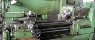
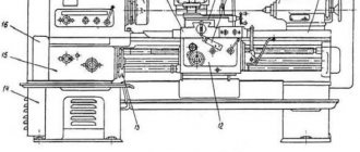
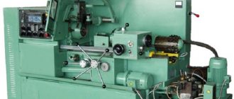
The main components that make up a metal lathe
Any metal lathe includes basic structural components and elements.
bed
The main and largest element on which all other parts are attached. This is a stationary part, consisting of two parallel walls, fixedly connected to each other by crossbars. The bed has cabinet legs in which the tool is stored.
The top rails serve as guides along which the lathe support and tailstock move. They can be flat or prismatic. The guides are made strictly parallel to each other.
Headstock
This part may also be called a spindle head. Inside it are the following parts:
- spindle;
- bearings (two);
- pulley;
- gearbox.
The headstock supports the workpiece and gives it rotation.
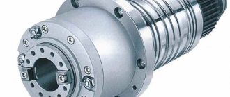
Spindle
The spindle is the main part of the headstock. It is a cone-shaped metal shaft. It holds various tools, mandrels and other devices.
The lathe spindle, journal and bearings must be smooth, cleanly ground, without backlash, because this affects the quality of boring parts. The spindle has a thread, and in some machines it also has a special groove so that the chuck does not unscrew spontaneously.
Transverse and longitudinal feed mechanism
The caliper can move lengthwise and crosswise thanks to the feed mechanism. The direction is set by a snaffle located in the headstock housing. There are handles on the outside of the machine that can be used to change the direction and amplitude of movement of the support.
Important!
If the machine has an automatic feed, then it has a lead screw and a roller. They are used to perform highly complex work.
Caliper
A support is a characteristic element of any lathe, with the help of which the cutting tool moves in the longitudinal, transverse and inclined directions. The longitudinal movement along the frame slide is carried out by the carriage, and the transverse movement is made by the upper part of the support. Tool holders (single or multiple) are installed in the upper part of the support.
Apron
Behind the apron body there are mechanisms connecting the caliper with the rack and lead screw. The apron control is located on the machine body, which simplifies the adjustment of the caliper stroke.
Tailstock
The tailstock is where the part is attached to the spindle, so this element is movable. The part consists of two parts: the lower one – the plate and the upper one – the spindle holder. The tailstock of the lathe moves along the bed and can be locked anywhere thanks to the lever handle. The cone of the tailstock is called a quill. A tool or device is attached to it. The tailstock also serves as a second support when processing long parts.
Carriage
The carriage is designed for longitudinal movement of the caliper along the bed slide. The free movement of this element depends on its serviceability.
Shaft
The spindle rotation shaft has two switching handles. When the handles are in the middle position, it is turned off. Up position – the shaft rotates counterclockwise (working movement), down position – the shaft rotates clockwise (reverse movement).
Headstock
The parts located in the headstock serve to support and rotate the workpiece during processing. There are also units here that regulate the speed of rotation of the part. These include:
- spindle;
- 2 bearings;
- pulley;
- gearbox responsible for adjusting the rotation speed.
The main part of the headstock in a lathe is the spindle. On its right side, facing the tailstock, there is a thread. Chucks that hold the workpiece are attached to it. The spindle itself is mounted on two bearings. The accuracy of the work performed on the machine depends on the condition of the spindle assembly.
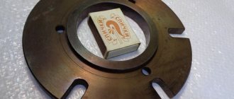
Gearbox top view
In the headstock there is a guitar of interchangeable gears, which is designed to transmit rotation and torque from the output shaft of the gearbox to the feedbox shaft for cutting various threads. Adjustment of the caliper feed is carried out by selecting and rearranging various gears.
Guitar of replacement gears of an Optimum lathe Guitar of a Soviet metal lathe
It is unlikely that you can still find a metal lathe with a monolithic spindle. Modern machines have hollow models, but this does not simplify the requirements placed on them. The spindle body must withstand without deflection:
- parts with heavy weight;
- maximum belt tension;
- cutter pressure.
Special requirements are imposed on the journals on which they are installed in bearings. Their grinding must be correct and clean, surface roughness no more than Ra = 0.8.
In the front part the hole has a conical shape.
Bearings, spindle and axle must, when operating, create a single mechanism that does not have the ability to create unnecessary runout, which can result from incorrect boring of the hole in the spindle or careless grinding of the journals. The presence of play between the moving parts of the machine will lead to inaccuracy in processing the workpiece.
The spindle is stabilized by bearings and a tension adjustment mechanism. It is attached to the right bearing using a bronze bushing bored out to the shape of the neck. On the outside, its bore coincides with the socket on the headstock body. The bushing has one through hole and several cuts. The bushing is secured in the headstock socket with nuts screwed onto its threaded ends. The bushing nuts are used to adjust the tension of the split bearing.
The gearbox is responsible for changing the rotation speed. A gear is attached to the pulley on the right, and a gear is mounted on the spindle to the right of the pulley. Behind the spindle there is a roller with a freely rotating sleeve with 2 more gears. Rotational motion is transmitted through the neck to the roller fixed in the brackets. Different gear sizes allow you to vary the rotation speed.
Overkill doubles the number of operating speeds of the lathe. The structure of a metal lathe using brute force allows you to choose an average speed between the base ones. To do this, it is enough to transfer the belt from one gear to the next or set the lever to the appropriate position, depending on the design of the machine.
The spindle receives rotation from an electric motor through a belt drive and gearbox.
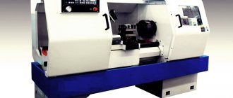
Design and operating principle
Most lathes are similar in design and have the same features. They differ only in size and location of some parts.
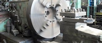
On lathes, parts are processed using a cutting tool as a result of rotation. With the forward movement of the cutter, a layer of metal is removed from the surface of the workpiece, and it is given the desired appearance and shape. Modern machines are highly accurate; threads can be cut to any profile.
The operating principle of a lathe is as follows:
- the tool for work is inserted into the tailstock quill;
- the tailstock must be installed in accordance with the dimensions of the part; it moves along the guides of the frame;
- a caliper is located between the front and tailstocks; during operation, it moves along the guides using a carriage;
- Tool holders are selected depending on the size of the part; they can be either single or intended for several cutters.
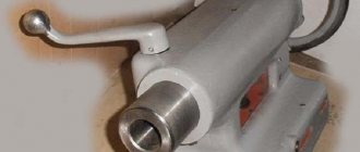
Purpose of the tailstock of turning equipment
, the design of which can include several design options, is necessary not only for fixing parts of considerable length, but also for fastening various tools: drills, taps, reamers, etc. The additional center of the machine, which is installed on the tailstock, can be rotating or stationary .
Tailstock structure: 1, 7 – handles; 2 – handwheel; 3 – eccentric; 4, 6, 9 – screws; 5 – traction; 8 – quill; A – counterbore
A scheme with a rotating rear center is used if the equipment is used for high-speed processing of parts, as well as when removing chips that have a large cross-section. When implementing this scheme, the tailstock is made with the following design: two bearings are installed in the quill hole - a front thrust bearing (with tapered rollers) and a rear radial one - as well as a bushing, the inner part of which is bored to a cone.
Axial loads arising during processing of a part are absorbed by a thrust ball bearing. Installation and fixation of the rear center of the equipment is ensured by the tapered hole of the bushing. If it is necessary to install a drill or other axial tool in such a center, the sleeve can be rigidly fixed with a stopper, which will prevent it from rotating with the tool.
Rotating center KM-2 of a table lathe Turner-250
The tailstock, the center of which does not rotate, is fixed to a plate that moves along the guides of the machine. The quill installed in such a headstock moves along the hole in it using a special nut. In the front part of the quill itself, into which the center of the machine or the shank of the axial tool is installed, a conical hole is made. The movement of the nut and, accordingly, the quill is ensured by the rotation of a special flywheel connected to the screw
What is important is that the quill can also move in the transverse direction; without such movement it is impossible to process parts with a flat cone
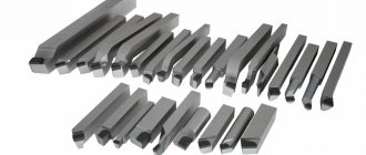
Options and explanation of modification options
The marking of equipment shows what features it has and its scope of application.
Lathes have a letter and a number name. Letter designations characterize its design features: level of automation, degree of processing accuracy, modification, type of CNC.
Meaning of letters in device markings:
- C – special accuracy.
- B – high accuracy.
- N – normal accuracy.
- A – particularly high accuracy.
- P – increased accuracy.
The numbers indicate:
- the first digit 1 indicates that it is a lathe;
- the second digit indicates the device type;
- the third and fourth show the processing features.
For example, 16K20T means:
- 1 – lathe;
- 6 – frontal type;
- 20 – 200 mm main parameter;
- T – modified.
Structure and application of CNC
A modern lathe has computer numerical control (CNC). The use of an electrical circuit and modification of the main components makes it possible to achieve high processing accuracy.
Features of CNC machines:
- When choosing equipment, you need to take into account the data specified in GOST. The accuracy class and other parameters are indicated there.
- The device has a complex electrical circuit and a mini-control unit.
- Despite their small size and weight, the models can withstand heavy loads.
- The device has a block on which all information is displayed. For this purpose, programming languages established by the standard are used.
- Equipment of small size and high precision is in demand. It produces parts for electronics and household appliances.
Adjustment and repair
The adjustment includes the required steps:
- setting the amount of play that forms between the guides at the bed and the base of the tailstock;
- minimum clearances in the quill bearings if it rotates;
- eliminating the center offset relative to the spindle.
How often it is necessary to check and its procedure are indicated in the passport documentation for each machine.
If the need arises, restoration or repair work is carried out. The following parameters are restored:
- precise joining of the frame with the tailstock assembly;
- height of the spindle and quill.
It is also often necessary to restore the accuracy of the hole where the quill is attached.
What parts can it process?
Lathes can process parts that have the form of a rotating body. These include:
- shafts;
- axles;
- disks;
- trunnions;
- flanges;
- couplings;
- rings;
- bushings;
- nuts, etc.
In addition, you can cut internal and external threads, turn and boring various surfaces, trimming ends, turning internal and external grooves, drilling, reaming holes, etc.
As you can see, a lathe is used for many operations and is necessary in any production. When considering different types of equipment, you need to keep in mind that the possibility of installing additional equipment can significantly expand the operations performed.