Excerpt from the text
INTRODUCTION
The relevance of the chosen topic of work. Today, any product that includes more than one part, as a result, refers to the combination of materials of these parts. At this point in time, the main method of permanently connecting parts (materials) is welding. Its advantage is that it has low labor intensity and makes it possible to save metal as much as possible [1, p. 33].
For example, replacing riveted joints with welded ones significantly reduces the weight of a product made from low-carbon steel by 15-30% due to a reduction in cross-sectional areas at the joints. Among other things, welding ensures a high coefficient of joint tightness, which is the main advantage when making a variety of tanks, containers, chemical apparatus, and so on.
In addition, it is also characteristic that welding equipment is very unpretentious in use, operation and maintenance, and it is noteworthy that this characteristic applies to almost all types of welding. In this work, it is advisable to consider manual arc welding as the most common in production [3, p. thirty].
Manual arc welding is a type of welding whose energy source is an electric arc. It is used when welding steels with a carbon content of ordinary quality. Manganese may also be present in the material. In addition, manual arc welding is suitable for working with low-alloy and alloy steels.
The purpose of writing an essay on the topic “Manual arc welding, its essence, current areas of application” is to study the purpose and scope of manual arc welding. To achieve this goal, it is necessary to solve a number of tasks:
- consider the theoretical essence of manual arc welding;
- study equipment for this type of welding;
- analyze the current scope of application of manual arc welding;
- draw appropriate conclusions based on the work done.
The object of the study is manual arc welding, the subject of the study is its essence and scope of application.
The information base for writing the work consisted of manuals on welding, welding production and reference publications.
The purpose and objectives of the abstract determined its structure, which consists of an introduction, three issues under consideration, a conclusion and a list of sources used.
Introduction
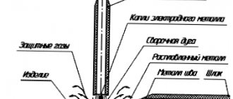
When welding with an electron beam, the penetration is cone-shaped. The metal melts at the front wall of the crater, and the molten metal moves along the side walls to the back wall, where it crystallizes.
Melting during electron beam welding is mainly caused by the pressure of the electron flow, the type of heat generation in the bulk of the solid metal and the reaction pressure of the evaporating metal, secondary and thermal electrons and radiation. Continuous electron beam welding is possible. However, during welding, metals (aluminum, magnesium, etc.) easily evaporate; the efficiency of the electron current and the amount of heat released into the product are reduced due to energy loss during ionization of metal vapor. In this case, it is useful to use a pulsed electron beam with a high energy density and a pulse frequency of 100 ... 500 Hz. As a result, the melting depth increases. By setting the pause/pulse time ratio correctly, very thin sheets can be welded. By dissipating heat during the pause, the length of the heat-affected zone is reduced. However, undercutting may occur and can be eliminated by welding with an oscillating or defocused beam.
Main parameters of electron beam welding mode:
- beam current;
- Acceleration voltage;
- speed of jet movement along the surface of the product;
- Pulse and pause duration;
- Beam focusing accuracy;
- Degree of vacuum.
To move the jet on the surface of the product, the product or the jet itself is moved using a deflection system. The deflection system allows the beam to oscillate along and across the seam or along a more complex path. Low-voltage equipment is used when welding metal with a thickness of more than 0.5 mm to obtain welds with a depth-to-width ratio of up to 8:1. High-voltage units are used for welding thick metal with a depth-to-width ratio of up to 25:1.
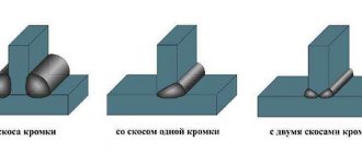
The main types of welded joints recommended for electron beam welding are shown in Figure 2. Before welding, precise assembly of parts is required (with a metal thickness of up to 5 mm, the gap should not exceed 0.07 mm, with a thickness of up to 20 mm, the gap should not exceed 0, 1 mm) and the exact direction of the beam along the axis of the connection (deviation no more than 0.2...0.3 mm).
For larger gaps (to avoid undercutting) additional metal is required in the form of process bottles or cored wire. In the latter case, there is the possibility of metallurgical influence on the weld metal. By changing the gap and the amount of filler metal, the proportion of filler metal in the weld can be increased to 50%.
Electron beam welding has significant advantages.
A high concentration of heat entering the product, which is released not only on the surface of the product, but also at a certain depth in the volume of the base metal. By focusing an electron beam, it is possible to create a heating spot with a diameter of 0.0002 ... A diameter of 5 mm, which allows you to weld metals with a thickness of tenths to 200 mm in one pass. As a result, it is possible to obtain seams where the ratio of the depth of destruction to the width of destruction is 20:1 or more. It is possible to weld refractory metals (tungsten, tantalum, etc.), ceramics, etc. Reducing the length of the heat-affected zone reduces the likelihood of recrystallization of non-ferrous metal in this zone.
Low heat input. To achieve the same penetration depth during electron beam welding, 4 ... 5 times less heat than is required for arc welding. This reduces distortion of the workpiece.
Lack of saturation of molten and heated metal with gases. On the contrary, in a number of cases, degassing of the weld metal occurs and its plastic properties increase. As a result, high quality welded joints are achieved on chemically active metals and alloys, such as niobium, zirconium, titanium, molybdenum, etc. Good quality electron beam welding is also achieved on low-carbon, corrosion-resistant steels, copper and copper, nickel and aluminum alloys.
This is an explosive seam. Heat is generated as a result of friction between the materials being joined. Friction is the result of an explosion that compresses the contact surfaces of the parts. This method is used to coat metals with foreign material. For example, steel is coated with aluminum.
This type of welding includes several options, which we will now consider.
List of used literature
LIST OF SOURCES USED
1. Anisimov E. M. Welding. M.: Mechanical Engineering, 2015. – 345.
2. Danilin A. N. Fundamentals of manual arc welding. M.: Mechanical Engineering, 2013. – 213.
3. Lukmanov G.D. Welder’s Handbook. M.: INFRA-M, 2021. – 984 p.
4. Nesterov O.I. Advantages and disadvantages of manual arc welding. M.: INFRA-M, 2011. – 220 p.
5. Sultanov P. Ya. Welding: from A to Z. M.: Mechanical Engineering, 2011. – 770 p.
Similar works
Essence, content and significance of stage 2 of judicial proceedings
Essence, content and forms of progress monitoring
Essence, content, organizational foundations, development trends.
economic reforms: essence, content, direction
Essence content and concept: vision, mission, strategic goals
thermal processes in manual arc welding
DETERMINATION OF MANUAL ARC WELDING MODES
Areas of application of the LISP language
Cost-based approach to property valuation. Concept. Essence, calculation procedure and scope.
Arc welding
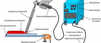
This type of welding is the most commonly used. The materials and/or parts being welded are melted by the heat generated by the arc. After hardening, the welded surfaces form a single welded joint. This type of welding requires a high current, low voltage power supply. The welding electrode is connected to its clamp, which, in turn, touches the workpiece to be welded.
The most important "subtypes" of electric arc welding are: manual arc welding, non-flammable electrode welding, fusion welding, submerged arc welding, electroslag welding.
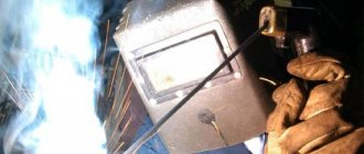
This is a universal technological process. With its help, you can perform welding work in any spatial position, from different types of steel, even without the necessary equipment. A special flux-coated electrode is used. The coating serves to protect the metal seam from external influences. Welding is carried out using direct current with direct or reverse polarity and alternating current. This type of welding is used for short and curved welds in hard to reach areas and for installation work.
A graphite or tungsten rod is used as an electrode. The melting point of these materials is higher than the temperature at which the welding process occurs. Welding is usually performed in an inert gas environment (argon, helium, nitrogen and mixtures thereof) to protect the weld and electrode from exposure to the atmosphere. Welding can be done with or without filler metal. Metal rods, wire, and strips are used as filler material.
The electrode is a wire (steel, copper or aluminum), which is supplied with current through a conductive tip. An electric arc melts the wire and the wire is automatically fed by the feeder to ensure a constant wire length. To protect against atmospheric influences, protective gases (argon, helium, carbon dioxide and their mixtures) are used, which are supplied along with the electrode wire from the welding head.
Appearance and development of welds
Welding is the process of forming permanent joints by creating atomic bonds between the parts being welded by local or general heating or plastic deformation, or by the combined action of both forms.
In 1802, for the first time in the world, V.V. Petrov (1761-1834), a professor of physics at the Medical-Surgical Academy of St. Petersburg, discovered the electric arc, described the phenomena occurring in it and pointed out the possibility of its practical application.
In 1881, Russian inventor N.N. Benardos (1842-1905) used an electric arc to join and separate steel. Electric arc N.N. Benardos was burned between the carbon electrode and the weld metal. The steel wire served as an additional rod to form the connection. Batteries were used as a source of electrical energy. The one from N.N. The welding proposed by Benardos was used in Russia in the workshops of the Rigo-Orlovskaya Railway for the repair of rolling stock. Other types of welding were also proposed by N.N. Benardos discovered: resistance spot welding, arc welding with multiple electrodes under shielding gas and mechanized feeding of the electrode into the arc.
In 1888, Russian engineer N.G. Slavyanov (1854-1897) proposed arc welding with a consumable metal electrode. He developed the scientific foundations of arc welding, used flux to protect the metal of the weld pool from exposure to air, and proposed surface welding and welding of cast iron. N.G. Slavyanov manufactured a welding generator according to his design and organized the world’s first electric welding workshop in the Perm cannon workshops, where he worked from 1883 to 1897.
N.N. Benardos and N.G. Slavyanov initiated the automation of welding processes. However, under the conditions of Tsarist Russia, their inventions were not widely used. Only after the Great October Socialist Revolution did welding become widespread in our country. Already in the early 1920s. under the guidance of Professor V.P. Vologdin in the Far East, ships were repaired by arc welding, like welded boilers, and later by welding ships and critical structures.
The development and industrial application of welding required the development and production of reliable power sources for stable arc burning. Such devices - the SM 1 welding generator and the ST 2 welding transformer with normal magnetic leakage - were first manufactured in 1924 by Leningrad. In the same year, Soviet scientist V.P. Nikitin developed a fundamentally new circuit for a welding transformer of the STN type. The production of such transformers began in 1927.
In 1928, scientist D.A. Dulchevsky invented automatic submerged arc welding.
A new stage in the development of welding dates back to the late 1930s, when the team of the Institute of Electric Welding of the Academy of Sciences of the Ukrainian SSR under the leadership of Academician E.O. Paton developed an industrial method of automatic submerged arc welding. Its introduction into production began in 1940. During the war, submerged arc welding played a major role in the production of tanks, self-propelled guns and aircraft bombs. Later, a semi-automatic submerged arc welding method was developed.
In the late 1940s, gas welding began to be used in industry. Teams of the Central Research Institute of Mechanical Engineering Technologies and E.P. The Paton Electric Welding Institute developed and introduced semi-automatic carbon dioxide welding in 1952.
The main achievement of welding equipment was the development by the KES team in 1949 of the electroslag welding method, which made it possible to weld metals of almost any thickness.
The authors of works on carbon dioxide consumable electrode welding and electroslag welding K.M. Novozhiliv, G.Z. Voloshkevich, K.V. Lyubavsky and others were awarded the Lenin Prize.
In subsequent years, ultrasonic welding, electron beam welding, plasma welding, diffusion welding, cold welding, friction welding, etc. were used in the country. Scientists of our country made a great contribution to the development of welding: V.P. Vologdin, V.P. Nikitin, D.A. Dulchevsky, E.O. Patonov and the team of E.O. Patonova, Central Research Institute of Mechanical Engineering Technology, All-Union Research Institute of Autogenous Mechanical Engineering, Institute of Metallurgy named after A.A. Baykova, Leningradsky, etc.
Welding has in many cases replaced labor-intensive structural processes such as riveting and casting, threading and forging.
The advantages of welding over these methods are as follows:
- Metal savings - 10 ... 30% or more depending on the complexity of the design
- reduction of labor intensity, reduction of work duration and reduction of its cost
- Cheaper equipment
- Machineability and automation of the welding process
- Possibility of wear repair
- The tightness of welded joints is higher than that of riveted or threaded joints.
Reducing production noise and improving working conditions for workers
Semi-welding machine A 547U
Semi-automatic machine A 547U is designed for welding in a carbon dioxide environment. Allows you to weld metal seams with a thickness of 1 mm or more, as well as fillet seams on seam catheters of 1.5 mm or more. Thanks to a small weld pool formed from thin electrode wire (up to 1.2 mm), it is possible to weld seams located in any spatial position with their free formation. Welding is performed with direct current with reverse polarity. Welding converters or welding rectifiers with rigid external properties can be used as a current source.
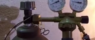
The general view of the semi-automatic machine complete with welding rectifier BC 300 is shown in Fig. 130. The set contains: Feeder 5, welding rectifier 6 with built-in control panel 7, holder 4 with hose, reducer - flow meter 3, heating gas 2, gas cylinder 1 with carbon dioxide, as well as connecting cables and wires.
The feed mechanism is designed in such a way that the electrode wire is inserted into the arc zone. It is installed together with a drum 2 of electrode wire and a gas separator 14 in a housing 13, which has the shape of a small housing with a cover 1. The DC motor 12 transmits rotation through a reduction gear 17 to a replaceable feed roller 5. Under this roller on the eccentric 7 there is a pressure ball bearing 6. The electrode wire is pressed against the feed roller using lever 9, reinforced on bracket 3. The pressure force is regulated by a spring located inside the pressure screw 4, the end of which presses the lever shaft and turns it to the axis 10. On the other side of the housing there is a pin 20, on which a drum with electrode wire is placed. There is a guide tube 8 between the drum and the feed roller. To connect the wires of the control circuits, there are connectors 16 and 21 on both sides of the housing. Carbon dioxide from the cylinder through nipple 22 is supplied to the gas separator, and then through tube 15 to the burner. The tip of the flexible tube is inserted into the contact jaws 18 and clamped with a pin 19.
The feeder is installed at the workplace and carried by the welder on handle 11. When working in stationary conditions, the feed mechanism is fixed on the welder’s table. In this case, instead of a drum with electrode wire, it is advisable to use the wire directly from the compartment, which is placed on the tray.
The semi-automatic machine comes with two types of hose holders. One of them, 1.2 m long, is intended for welding with electrode wire with a diameter of 0.8 - 1 mm at a current of up to 150 A, and the second, 2.5 m long, is used for welding with wire with a diameter of 1 - 1.2 mm at a current of up to 250A.
If the radius of action of the welding wire is greater than specified, then the splashes of metal on the electrode increase and the welding process is disrupted; if the range is less, the tip burns out. The flight sequence and reliability of the tip are guaranteed by the contact sleeve. One contact sleeve is used for curved cutters, and two for straight cutters.
Welding in different positions of the seam in space is performed in different modes. When moving from bottom to vertical connections, the mode (tension and wire feed speed) should be reduced. Frequently changing the welding mode by hand removes the welding machine and takes a lot of time, so some semi-automatic machines are equipped with remote control devices for the welding mode. Devices for remote mode switching make semi-automatic machines suitable for starting and finishing welding.
Active gases are used as protective gases, i.e. those that can interact with other elements during the welding process. These gases include carbon dioxide (CO2) or mixtures: 70% carbon dioxide and 30% argon (or oxygen) for welding carbon steels; 70% argon and 30% carbon dioxide for welding alloy steels.
Using gas mixtures instead of 100% carbon dioxide increases productivity and quality of welds.
The advantage of gas welding is also that durable anti-corrosion layers (galvanized, etc.) can be applied to the welded products made using this technology without any special preparation. Inert gas welding is also used to join thin metals (0.1 - 1.5 mm).
Of all types of arc welding, semi-automatic gas shielded welding has the least amount of work.
Carbon dioxide. At normal atmospheric pressure, the specific density of carbon dioxide is 0.00198 g/cm³. At a temperature of 31°C and a pressure of 7.53 MPa, carbon dioxide liquefies. The temperature of gas liquefaction at atmospheric pressure is 78.5o C. Carbon dioxide is stored and transported in steel cylinders under a pressure of 6 - 7 MPa. A standard cylinder with a volume of 40 dm³ holds 25 kg of liquid carbon dioxide, resulting in the formation of 12,625 dm³ of gas upon evaporation. Liquid carbon dioxide occupies 60-80% of the tank volume, the rest of the volume is filled with evaporated gas.