1 / 1
, pulse welding is gaining increasing popularity . This non-contact method of joining metals was first used almost 90 years ago. Created as an alternative to the electric arc method, it is, in fact, a subspecies of it.
The difference is that additional pulses are superimposed on the constant welding current with a given amplitude. These bursts of energy can be several times higher than the background current. The formation of the seam occurs sequentially using the drip method. This technique eliminates metal spattering and allows you to join even thin sheet material without the risk of burning through it.
Pulse welding: how does it work?
This welding method requires a semi-automatic welding machine with a pulse mode function
.
Electrodes can be either fusible (MIG)
or
non-melting (TIG)
. The process itself is cyclical with drops of filler material sequentially falling into the weld pool (one pulse - one drop). The welding machine transforms the mains voltage into direct current and rectifies the current, then increases the frequency with a given amplitude.
In the background, a constant welding current is supplied, the task of which is to maintain a stable arc. During sudden load surges, the end of the filler wire melts. Electrodynamic forces thin the neck of the resulting drop, and the liquid metal, under the influence of its weight, falls onto the surfaces being connected, forming a seam. Then the current instantly drops to the standby value. During this period of time, the temperature in the weld pool decreases and the metal solidifies. Then the process is repeated.
Pauses between flashes can be adjusted by the device settings. This provides the ability to select different welding modes and control the parameters of the resulting seam.
Types of pulsed arc welding
Current conversion, during which a pulse is created, can be achieved in different ways:
- battery-powered;
- capacitor;
- electromagnetic;
- inertial.
Each of them has its own characteristics, which are worth talking about in more detail.
Battery current conversion method
Welding machines that support this type of pulsed arc welding are additionally equipped with an alkaline battery. It generates the amount of current required for the pulse. The specificity of such a battery is its low internal resistance. Due to this, the output voltage can be many times higher than the received one. And short circuits necessary for the occurrence of impulses are quickly neutralized.
So far, battery-powered current conversion is not widely used. The main reason for the lack of popularity is the cumbersome design. But the method is convenient and promising, so active developments are underway to improve it.
Capacitor energy conversion
The appearance of the very first pulse welding machines was based on this technology. It goes back to the 30s of the last century.
Here the pulse occurs due to a powerful discharge generated by a capacitor bank. In this case, the maximum current value can exceed 100 thousand amperes. Pulse units allow you to accurately dose the electricity needed for a voltage surge. The wide range of output current allows you to configure the device to the values most suitable for the welding process.
The scope of application is limited to the cross-section of the products being welded. In this case, the thickness of one of the parts should not exceed the capabilities of the apparatus, and the other, welded to it, can have any thickness. Therefore, at the dawn of the appearance of the capacitor method, it was used to connect sheet metal and weld various fasteners to it. Nowadays, capacitor pulse welding is widely used in electronics production and instrument making, where maximum accuracy is important. The method is ideal for welding stainless steel and aluminum.
Magnetic pulse method
Equipment for magnetic pulse welding works on the principle of converting electrical energy into mechanical energy. This creates a magnetic field that connects the parts under high pressure. Greater compression force and temperature create a weld. The process is based on the electromechanical properties of eddy current.
The process goes like this: the first part is fixed motionless, and the second is moved by the electromagnetic field that is generated by the welding machine. When the workpieces are brought closer together, a welding arc is created that holds them together.
The magnetic pulse method is widely used in machine-building industries. It allows you to weld tubular parts to each other or to flat surfaces, as well as join sheet metal along contours. In everyday life or in small enterprises, magnetic pulse welding is used extremely rarely. The setup process and technology are complex, and the equipment wears out quickly.
Inertial pulse welding
The generator of such a welding device has a powerful flywheel, which is spun by an electric motor. During the unwinding process, the required kinetic energy is accumulated. At the moment the rotation speed decreases, inertial resonance occurs and is transformed into a welding current pulse. A pulse inverter serves as a welding machine.
ISA models
In recent years, the ISA market has grown significantly and it has become more difficult to choose a device among such a variety.
In this article we will figure out how to find a pulse inverter model for working at home and in the country, based on the experience of professionals and beginners.
Let's make a rating of pulse inverters that are well suited for working at home.
EUROLUX IWM 190
Our list opens with the inverter pulse Eurolux IWM 190. It belongs to the category of budget ISA and has already become in demand among “amateur” welders.
Its price does not exceed $70. Its qualities are not inferior to inverters with more well-known names.
This model is designed for manual MMA arc welding. It is ideal for home use because small diameter rods can be used. Despite its light weight and size, its power is 190 amps.
Eurolux IWM 190 has no additional functions. The price of a welding machine would increase significantly if it had additional functions such as anti-sticking or a forced arc.
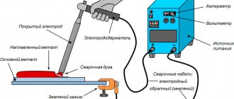
The set of this pulse machine includes: a ground clamp, an electrode holder, and welding cables.
Unfortunately, these components are not reliable, so we recommend purchasing them separately, so you can carry out any welding work without any problems.
This device is well suited for summer residents who have basic skills in using ISA or for a novice master. It is well suited for welding a gate or welding a greenhouse, and can also cope with any small tasks without any problems.
Pulse welding technology
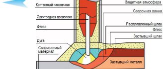
For pulse welding, inverter-type machines are used. To prevent the molten metal from coming into contact with air, shielding gas is supplied to the weld pool area. Thanks to this, the metal does not react with oxygen and does not oxidize.
The essence of pulsed-arc welding is the controlled transfer of metal from the filler wire or fusible electrode to the junction of the surfaces being welded. The process proceeds cyclically:
- The current increases sharply. The base material melts, forming a spot weld pool.
- The current decreases. The metal cools down and begins to harden from the edges to the center of the seam.
- The cycle repeats.
The seam is smooth and of high quality. It does not have to be cleaned from oxides and frozen splashes. Each pulse transfers only one drop of filler material into the weld pool. At the same time, its parameters are easy to change. The current frequency can vary from 0.5 to 300 Hertz.
What is better to choose
The most popular method is semi-automatic welding. The apparatus intended for it consists of a torch and an automatic wire feed mechanism. The method differs from other technologies in increased productivity and continuous operation.
The disadvantage of the semi-automatic method is the splashing of metal during operation. More than 30% of filler wire is wasted. Because of the splashes, the seam has to be cleaned, and the aesthetic qualities of the structure deteriorate.
It is recommended to choose pulse welding, which does not have these disadvantages. Using the method increases the strength of the connection.
We recommend reading Description of the thermite welding process
Pulse welding algorithm
Some modern inverters have a synergic (pulse) operating mode. During the welding process, the strength and voltage of the current with a given rhythm change from the lower value to the upper one. The range from 0.5 to 300 Hz is available for setting the pulse frequency. As it increases, the arc narrows and the grain size decreases, the seam becomes narrower, and the penetration depth increases. Reducing the frequency allows for better control of the process.
The synergetic mode produces a seam formed by overlapping points. The weld pool is smaller than in the case of direct current, but its depth is sufficient to ensure good penetration. The maximum effect is achieved when there is a sufficient temperature difference between the pulse and the background current.
The algorithm is configured by changing the pulse and pause current values and their duration. The background current is selected to be less than the minimum recommended for melting the metal being welded. During the pause between flashes, the weld pool must have time to cool and crystallize. And the magnitude of the pulse current should ensure optimal melting. In this case, the properties of the material being welded should be taken into account.
Advantages
Pros
The pulse-arc method has many:
- A high-quality, tightly formed weld seam that does not have to be cleaned up afterwards.
- You can cook any metal, including aluminum and stainless steel. Moreover, in this way it is possible to connect alloys of different chemical compositions together.
- A minimal amount of additional equipment is required to operate.
- The arc and shape of the weld pool are easy to control. This is also facilitated by the fact that the work area is not clouded with smoke.
- The metal drips onto the seam in a directional manner, there is no spattering, and filler material is saved.
- The heat input is significantly lower than with conventional welding. Parts are not deformed under high temperature. You can even work with thin sheet steel without the risk of burning it.
- The welder does not require high qualifications; even a beginner can produce a beautiful “scaly” weld.
Flaws
The pulse welding method is considered to be highly specialized. In TIG mode, productivity is not as high as we would like, and MIG welding places high demands on shielding gases. In addition, the additional equipment required makes the purchase more expensive.
An energy converter in pulse mode is prone to overheating. Therefore, during active work it is worth thinking about additional cooling. The same fact excludes the possibility of continuous work with large volumes.
Conservative welders criticize the pulse method because the parameters of the weld pool are set by settings on the machine, and there is no way to fully feel the process. Although this is a matter of individual habit.
Another reason for dissatisfaction may be the need to select modes for each specific case. But modern welding machines can be equipped with many ready-made programs suitable for different tasks.
Advantages of pulsed MIG welding
The main feature of this method is the non-contact method of transferring the melt from the wire to the welding zone. In combination with a pulsed current mode, this approach provides the following advantages:
- Saving gas and wire resources. Consumables with lower parameters are used, and the protective gas environment can be used for various tasks without the selection of additional torches and tips.
- Low smoke and spatter. Again, due to a higher degree of control and power costs, the thermal impact process is, in principle, optimized and negative factors are reduced.
- High performance. In the MIG mode, pulsed welding provides higher melt efficiency with the same technical and operational parameters of the equipment.
- Reliability and safety. Comprehensive control of the welding process is expressed not only in the regulation of spatter and automation of individual functions, but also in the support of a whole set of protective options with shutdown in case of overheating.
Scope of application
Pulsed argon arc welding is indispensable in cases where it is necessary to conduct the seam vertically
or
in an inverted (ceiling) state
, when the force of gravity interferes. At home or in small workshops, it happens that the metals being welded do not shine with quality, but if you add impulses to the process, the work will become easier.
Initially, pulsed argon welding was created to work with stainless steel and it copes with this task perfectly. Aluminum can be successfully welded using the same method. But what is especially valuable is that the pulse-arc method allows you to connect different types of non-ferrous metals and steel with different chemical compositions. The thickness of materials that can be worked with ranges from 0.5 to 50 mm.
Weaknesses of pulse welding
Like all welding technologies, including modern ones, the pulse method is not without its drawbacks. Despite its pronounced advantages, it is rarely used in solving typical problems due to the high cost of equipment, increased organizational costs and a number of negative technological nuances. In particular, the TIG pulse welding mode is characterized by low productivity and low wire feed speed. The use of other modes is limited by high requirements in terms of the selection of mixtures with protective gases. That is, the method is mostly highly specialized and is only suitable for use in individual operations under certain conditions.
Pulse welding machines
There is a lot of information on the Internet about how to assemble a pulse current welding machine with your own hands. With the appropriate knowledge, this is not difficult to do. But the functionality and capabilities of such technology will be mediocre. The price of spare parts and the time spent are unlikely to be fully justified.
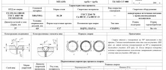
It is much more profitable to buy a universal welding inverter that allows you to work with both direct current and pulsed current. Such units include the KEDR MULTITIG-2000P DC argon arc welding installation . Its functionality allows you to solve even complex problems. This is a universal machine suitable for welding all types of materials - from alloy steel to aluminum, stainless steel, nickel and titanium. At the same time, its compact size allows it to be used in hard-to-reach places and at heights.
Pulse current mode: nuances of setting up a welding machine
Let's consider the choice of modes using the example of the above-mentioned argon arc welding machine KEDR MultiTIG-2000P DC. The device has a wide range of settings suitable for both beginners and professionals. The setting is performed using the regulator located on the control panel. The pulse TIG welding mode allows you to change the parameters of peak and base current, balance and pulse frequency.
By setting the pulse and background current, the amplitude of voltage fluctuations during argon TIG welding is set in the range from 5 to 200 Amperes. This allows you to control heat input and penetration depth.
Pulse balance is the ratio of the duration of the pulse and base current. It also affects the amount of heat input into the base metal. Adjustable from 5 to 95%.
The pulse frequency directly affects the operating speed and penetration depth. Adjustment limits from 0.5 to 200 Hz.
Is it worth learning the pulse welding method? If you use a welding machine for household needs a couple of times a year, then this may not be necessary. In all other cases - definitely yes. Today this is one of the most promising methods. Pulse welding is increasingly used in workshops, car services and small industries. When working with thin-walled metals, as well as where it is necessary to apply vertical and ceiling seams, this is the best choice.
Further customization
All power elements of the circuit must have high-quality cooling. Transistor switches must be “seated” on thermal paste and a heatsink. It is advisable to use radiators from powerful microprocessors (Athlon). The presence of a fan for cooling in the case is mandatory. The power supply circuit can be modified by placing a capacitor block in front of the transformer. You need to use K78−2 or SVV-81, since other options are unacceptable.
After the preparatory work, you need to start setting up the welding inverter . To do this you need:
- Connect 15V to the PWM, supplying power to the PWM and to the cooling system. Relay K1 acts as a key for closing R11 - with the first response time being about 10 seconds. In addition, C9-C12 is charged, which are discharged through R11. The presence of R11 is mandatory, as it will protect the capacitors from explosion due to a current surge when mains power is supplied.
- Using an oscilloscope, check the board for the presence of rectangular pulses going to the HCPL3120 after K1 and K2 are triggered. In addition, relay K1 must be connected after charging the capacitors. When the inverter is operating without load (idling), the current should be less than 100 mA.
- The correct phase setting of the high-frequency transformer is checked with a 2-beam oscilloscope. To do this, you need to set the PWM frequency to 50..55 Hz and measure the value of U, which should be less than 330 V. The bridge consumption should be 120..150 mA. When the welding inverter is operating, the transformers should not make much noise, and if this happens, you need to figure it out. The noise often occurs due to poorly clamped magnetic circuit plates. Look at the oscilloscope and smoothly turn the variable resistor knob.
- U parameters should not exceed 540 V (345 V is the optimal U value). After measurements, you need to disconnect the oscilloscope and start welding the metal. The welding time should start at 10 seconds and gradually increase it to 5 minutes. If everything is done correctly, there should be no noise.
There are also more advanced models of inverter-type welders, the power circuit of which includes thyristors. The Timvala inverter, which can be found on amateur radio forums, has also become widespread. It has a more complex scheme. You can find out more about it on the Internet.
Thus, knowing the structure and operating principle of an inverter-type welding machine, assembling it with your own hands does not seem to be an impossible task. The homemade version is practically not inferior to the factory one and even surpasses some of its characteristics.
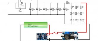
DIY PULSE WELDING MACHINE
Presented to your attention is a diagram of a pulse-type welding machine, which you can assemble with your own hands. Maximum current consumption is 32 amperes, 220 volts. The welding current is about 250 amperes, which allows you to easily weld with a 5-piece electrode, an arc length of 1 cm, which passes more than 1 cm into low-temperature plasma. The efficiency of the source is at the level of store-bought ones, and maybe better (meaning inverter ones). The power supply for the controller is made as a separate module and has three output stabilized voltages:
The transformer is wound on ferrite sh7x or 8x8, the primary has 100 turns of the wire PEV 0.3mm secondary 2 have 15 turns of the wire PEV 1mm secondary 3 have 15 turns PEV 0.2mm secondary 4 and 5, 20 turns of the PEV 0.35mm wire, all windings must be shook all over the width of the frame , this gives a noticeably more stable voltage.
Figure 2 shows a diagram of the welder.
INCREASE
POWER TRANSFORMER OF WELDING MACHINE
The frequency is 41 kHz, but you can try 55 kHz. The transformer at 55 kHz is then 9 turns by 3 turns, to increase the PV of the transformer.
Transformer at 41 kHz - two sets Ш20х28 2000nm, gap 0.05mm, newspaper gasket, 12vit x 4vit, 10kv mm x 30kv mm, copper tape (tin) in paper. The transformer windings are made of copper sheet 0.25 mm thick and 40 mm wide, wrapped in cash register paper for insulation. The secondary is made of three layers of tin (sandwich) separated from each other by fluoroplastic tape, for insulation between themselves, for better conductivity of high-frequency currents, the contact ends of the secondary at the output of the transformer are soldered together. Inductor L2 is wound on a Ш20x28 core, ferrite 2000nm, 5 turns, 25 sq.mm, gap 0.15 - 0.5mm (two layers of paper from the printer). Current transformer - current sensor two rings K30x18x7 primary wire threaded through the ring, secondary 85 turns of wire 0.5 mm thick.
Winding the transformer must be done using copper sheet 0.3mm thick and 40mm wide, it must be wrapped in thermal paper from a cash register 0.05mm thick, this paper is durable and does not tear as much as usual when winding a transformer. You tell me, why not wind it with an ordinary thick wire, but it’s not possible because this transformer operates on high-frequency currents and these currents are displaced onto the surface of the conductor and the middle of the thick wire is not used, which leads to heating, this phenomenon is called the Skin effect! And you have to fight it, you just need to make a conductor with a large surface, so thin copper sheet has this, it has a large surface along which current flows, and the secondary winding should consist of a sandwich of three copper tapes separated by fluoroplastic film, it is thinner and all these are wrapped layers in thermal paper. This paper has the property of darkening when heated, we don’t need this and it’s bad, it won’t do anything, let the main thing remain that it doesn’t tear. You can wind the windings with PEV wire with a cross-section of 0.5...0.7 mm consisting of several dozen cores, but this is worse, since the wires are round and are connected to each other with air gaps, which slow down heat transfer and have a smaller total cross-sectional area of the wires combined compared to tin by 30 %, which can fit into the ferrite core window. It is not the ferrite that heats up the transformer, but the winding, so you need to follow these recommendations. The transformer and the entire structure must be blown inside the housing by a 220-volt 0.13 ampere fan or more.
Read also: Borax for soldering composition
To cool all powerful components, it is good to use radiators with fans from old Pentium 4 and Athlon 64 computers. I got these radiators from a computer store doing upgrades, for only $3...4 apiece. The power oblique bridge must be made on two such radiators, the upper part of the bridge on one, the lower part on the other. Screw bridge diodes HFA30 and HFA25 onto these radiators through a mica spacer. IRG4PC50W must be screwed without mica through KTP8 heat-conducting paste. The terminals of the diodes and transistors need to be screwed towards each other on both radiators, and between the terminals and the two radiators, insert a board connecting the 300-volt power circuit to the bridge parts. The diagram does not indicate the need to solder 12...14 pieces of 0.15 micron 630 volt capacitors to this board into a 300V power supply. This is necessary so that the transformer emissions go into the power circuit, eliminating the resonant current surges of the power switches from the transformer. The rest of the bridge is connected to each other by hanging installation of conductors of short length. The diagram also shows snubbers, they have capacitors C15 C16, they should be brand K78-2 or SVV-81. You can’t put any garbage there, since snubbers play an important role: first , they dampen the resonant emissions of the transformer; second , they significantly reduce IGBT losses when turned off, since IGBTs open quickly, but close much more slowly, and during closing, capacitance C15 and C16 are charged through the VD32 VD31 diode is longer than the closing time of the IGBT, that is, this snubber intercepts all the power, preventing heat from being released on the IGBT switch three times than it would be without it. When the IGBTs open quickly, the snubbers are smoothly discharged through resistors R24 R25 and the main power is released on these resistors.
Apply power to the 15-volt PWM and at least one fan to discharge capacitance C6, which controls the relay response time. Relay K1 is needed to close resistor R11 after capacitors C9...12 are charged through resistor R11, which reduces the current surge when the welding machine is turned on to a 220-volt network. Without direct resistor R11, when turned on, there would be a large BAC while charging a 3000 μm 400V capacitance, which is why this measure is needed. Check the operation of the relay closing resistor R11 2...10 seconds after power is applied to the PWM board. Check the PWM board for the presence of rectangular pulses going to the HCPL3120 optocouplers after both relays K1 and K2 are activated. The width of the pulses should be relative to the zero pause 44% zero 66% Check the drivers on optocouplers and amplifiers that drive a rectangular signal with an amplitude of 15 volts to make sure that the voltage on the IGBT gates does not exceed 16 volts. Apply 15 Volt power to the bridge to check its operation and ensure that the bridge is manufactured correctly. The current consumption should not exceed 100mA at idle. Verify the correct phrasing of the windings of the power transformer and current transformer using a two-beam oscilloscope. One beam of the oscilloscope is on the primary, the second on the secondary, so that the phases of the pulses are the same, the only difference is in the voltage of the windings. Apply power to the bridge from power capacitors C9...C12 through a 220 volt 150..200 watt light bulb, having previously set the PWM frequency to 55 kHz, connect an oscilloscope to the collector-emitter of the lower IGBT transistor, look at the signal shape so that there are no voltage surges above 330 volts as usual. Start lowering the PWM clock frequency until a small bend appears on the lower IGBT switch indicating oversaturation of the transformer, write down this frequency at which the bend occurred, divide it by 2 and add the result to the oversaturation frequency, for example, divide 30 kHz oversaturation by 2 = 15 and 30 + 15 = 45 , 45 this is the operating frequency of the transformer and PWM. The current consumption of the bridge should be about 150 mA and the light bulb should barely glow; if it glows very brightly, this indicates a breakdown of the transformer windings or an incorrectly assembled bridge. Connect wires at least 2 meters long to the output of the welding machine to create additional output inductance. Apply power to the bridge through a 2200-watt kettle, and set the current on the light bulb to PWM at least R3 closer to resistor R5, close the welding output, check the voltage on the lower switch of the bridge so that it is no more than 360 volts according to the oscilloscope, and there should be no noise from the transformer. If there is one, make sure that the transformer-current sensor is correctly phased, pass the wire in the opposite direction through the ring. If the noise remains, then you need to place the PWM board and optocoupler drivers away from sources of interference, mainly the power transformer and inductor L2 and power conductors. Even when assembling the bridge, the drivers must be installed next to the radiators of the bridge above the IGBT transistors and no closer to the resistors R24 R25 by 3 centimeters. The driver output and IGBT gate connections must be short. The conductors going from the PWM to the optocouplers should not pass near sources of interference and should be as short as possible. All signal wires from the current transformer and going to the optocouplers from the PWM should be twisted to reduce noise and should be as short as possible. Next, we begin to increase the current of the welding machine using resistor R3 closer to resistor R4, the output of the welding machine is closed on the switch of the lower IGBT, the pulse width increases slightly, which indicates PWM operation. More current means more width, less current means less width.
There should not be any noise, otherwise the IGBTs will fail!
Add current and listen, watch the oscilloscope for excess voltage of the lower key, so that it does not exceed 500 volts, a maximum of 550 volts in the surge, but usually 340 volts. Reach the current where the width suddenly becomes maximum, indicating that the kettle cannot provide maximum current. That's it, now we go straight without a kettle from minimum to maximum, watch the oscilloscope and listen so that it is quiet. Reach the maximum current, the width should increase, emissions are normal, no more than 340 volts usually. Let's start cooking. At the beginning 10 seconds. We check the radiators, then 20 seconds, also cold, and 1 minute - the transformer is warm. I burned 2 long 4mm electrodes - the transformer is bitter. The radiators of the 150ebu02 diodes in the welding machine became noticeably hot after three electrodes, it’s already difficult to weld, a person gets tired, although he cooks great, the transformer is hot, and no one welds anyway. After 2 minutes, the fan brings the transformer to a warm state and you can cook it again until it becomes puffy.