We recommend purchasing:
Installations for automatic welding of longitudinal seams of shells - in stock!
High performance, convenience, ease of operation and reliability in operation.
Welding screens and protective curtains are in stock!
Radiation protection when welding and cutting. Big choice. Delivery throughout Russia!
The difficulty of welding butt joints with grooved edges and fillet welds lies in the fact that welding is carried out in cramped conditions.
The distinctive features of welding are as follows:
1) the cutting edges do not allow liquid slag to flow down the edges of the roller;
2) there is more slag per unit surface area of the weld metal than when welding a bead on an open surface;
3) due to the large amount of liquid slag, it rolls onto the welding arc;
4) the slag coming in front flows down the groove and interferes with the welding process, which leads to lack of penetration and slagging. In this case, welding must be done at an angle back. When welding critical products that are subject to all types of control, special requirements are imposed on butt welds when performing all operations.
I. Welding the first root bead in a butt joint
Welding the first root bead in a butt joint is the most difficult and requires special skills and a lot of training from the welder.
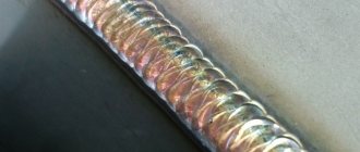
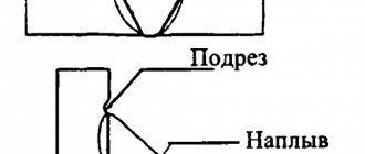
The completed roller should be “normal” or “concave”, with fusion on both edges, without undercuts, and with good formation on the reverse side. All this is achieved with a certain combination of selection of welding current, welding speed, arc length, tilt and manipulation of the electrode.
When welding the first root bead into a gap with a V-shaped edge groove (Fig. 31a), an electrode with a diameter of 3 mm is used, a welding current in the range of 85 ± 5 amperes, depending on the thickness of the metal, the gap and the bluntness.
When welding V-shaped (Fig. 31b) and X-shaped groove (Fig. 31c), electrodes with a diameter of 3-4 mm are used (it is recommended to use an electrode with a diameter of 4 mm). The length of the bead of one electrode with a diameter of 4 mm is 2-3 times greater than the length of the bead welded with an electrode with a diameter of 3 mm. The number of electrode connections (start and end of welding) is reduced, which reduces the possibility of defects and dramatically increases productivity. Welding current for an electrode with a diameter of 3 mm - 90 A ± 5 A, 4 mm - 140 A ± 5 A.
Having selected the electrode diameter and welding current depending on the assembly and the above conditions, it is recommended to weld into the gap of the first bead in three ways:
1st method
- without manipulation (Fig. 32). This method is possible with the combination of the minimum recommended current in the V-shaped and the minimum or average in the X-shaped groove, the average arc length at a certain gap and blunting of the edges and the thickness of the metal. Observing the melting of both edges and the dulling of the welding arc and the filling of the gap with liquid electrode metal, it is necessary to perform a translational movement at a certain speed, which does not allow gaps in the connection of the edges at high speeds and burns at low speeds.
Maintain an angle of inclination of the electrode relative to the welding direction of 90 ± 10°. Welding at a “right angle” and “forward angle” in the groove is only possible when welding the first bead into the gap, because part of the liquid slag coming in front flows into the gap and protects the liquid metal of the weld on the back side of the product.
In case of insufficient clearance (during assembly) or tightening of edges and other reasons during the welding process, the slag coming in front does not have time to flow into the gap and its excessive accumulation occurs in front of the electrode, which can lead to lack of penetration of the weld root.
In this case, it is necessary to weld at a “backward angle”.
In the case where the gap in combination with other parameters turns out to be large and excessive penetration or welding on the verge of burn-through occurs, it is necessary to use “forward angle” welding. In this case, the impact on the bluntness and gap occurs not directly (“open arc”), with maximum penetration, but through the liquid metal, going slightly ahead. At the same time, carefully observe that the liquid metal moving in front of the electrode (it turns out that with a translational movement of the electrode we “roll” the liquid metal ahead) melts both edges of the blunting, connecting them with the electrode metal. This is possible at a certain welding speed, which must be determined by the welder.
2nd method
- with manipulation of the electrode - “forward back”. Without changing the inclination of the electrode, to avoid burn-through, act with an “open arc” on the edges in the gap and perform reciprocating movements. When returning to the crystallizing roller (8-12 mm), the place where the crater transitions into the gap is frozen. Then move forward again, melting the edge of the crater and the blunt edges in the gap with an open arc.
The distance for the open arc to pass over the gap depends on all the conditions listed above. Therefore, the welder himself must navigate and choose the best option.
3rd method
- with manipulation of the electrode (Fig. 33) - “ladder”, in the case when excessive penetration occurs, you recommend making transverse oscillatory movements from one edge to the other. The transition over the gap is very important. If the blunt edges do not melt, it means the transition is too fast and the arc length is too long. When crossing over the gap, it is necessary to reduce the length of the arc, and when approaching the cutting edge, climb up it slightly and make a short arc at the point of delay (as if pressing the electrode against the workpiece). The delay is necessary to remove heat from the gap, to warm up the edge and to fill the crater with electrode metal. The transition to the other edge should be carried out (without fuss) calmly (to avoid undercutting on the edge). Depending on the penetration of the blunt edges, pass either through the gap (as if going down) or above the gap, maintaining the selected height of the bead from the gap. Electrode inclination relative to welding direction 90° ±10°
The beginning and end of welding (when replacing the electrode) is of great importance on the quality of the root bead.
If the welder is insufficiently qualified when welding the first root bead (into the gap), “dimples” are formed on the reverse side at the junction of the electrodes when forming the root of the weld, i.e. deep lack of fusion (Fig. 34). It is necessary to carry out deep mechanical sampling of the back side of the root weld, even in the presence of a well-formed back bead.
To avoid sampling, it is necessary that:
1. The height of the root bead did not exceed the diameter of the electrode.
2. The crater at the end of the electrode remained flat.
3. Before igniting a new electrode, thoroughly clean the crater and especially the end of the crater, which turns into a gap, and the gap itself from solidified slag. If necessary, clean the crater mechanically with a smooth transition into the gap.
4. Ignite the new electrode at the top of the crater, connecting the first flake with the last flake of the frozen roller (Fig. 35).
When descending along the crater from position (1) to the gap, it is necessary to prevent liquid slag from leaking under the arc into the gap (by correctly choosing the angle of the electrode and the speed of advance). Before reaching the end of the crater, from position 2, quickly move the electrode (while aligning the inclination of the electrode to 90° to the welding direction) to position 3 and, using an open arc, hold the center of the arc at the point where the crater transitions into the gap with a short arc length. The delay time is determined as follows. At the beginning, most of the arc burns on the other side of the gap, i.e. on the reverse side, which allows the jumper to be melted on both sides. And after the electrode metal fills the gap in the place of delay and the arc mainly burns from the welding side, begin forward movement using one of the methods chosen by the welder. All this will allow you to form the root of the seam on the reverse side with minimal differences in the places where the electrodes are replaced and to avoid deep “dimples”. With a well-formed return roller, no picking is required, which reduces material consumption and increases labor productivity.
Note. You can start a new electrode without damaging the slag. This is an ideal option for high-quality joining of the end and beginning of welding, but it requires high skill, dexterity in quickly replacing the electrode (not every holder has such an opportunity) and a number of other factors when the crater does not have time to solidify and the slag is still liquid (semi-liquid) and red, all this allows for easy ignition of the electrode and good penetration at the joint. Such ignition eliminates the formation of starting pores. This is possible, we repeat, only if the crater is not solidified.
In this way, you can weld the root of the seam using two welders in an “interception”.
Before preparing for welding the reverse side of the groove, it is necessary to lay 1-2 more beads on the first root bead (depending on the thickness of the metal) to increase the cross-section of the seam in height. This is required so that if the reverse side is removed, a thin section of the first root bead will not remain. If the width of the previous roller allows, switch to a larger electrode diameter. Welding current - average or maximum. Welding should be done at a backward angle. The angle of inclination of the electrode depending on the location of the slag. Maintain the welding speed so that the beads are without reinforcement, without undercuts along the edges of the seam. Manipulate the electrode depending on the width of the previous and the beads being performed, with a mandatory delay for the cutting edge. The delay is necessary to warm up the edges, which contributes to better bead formation and the elimination of undercuts along the edges of the seam
Lecture No. 13. Technology and technique for making seams in the lower position.
⇐ PreviousPage 8 of 14Next ⇒Bottom seams are the most convenient for welding, since in this case drops of electrode metal under the influence of their own weight easily pass into the weld pool and liquid metal does not flow out of it. In addition, observing welding with the seam in the lower position is more convenient. (Fig.18)
Fig. 18 Making welds in the lower position
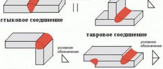
Butt welds are used to produce butt joints.
When making butt welds, welding is carried out in four directions: from left to right, from right to left, towards you, away from you.
The inclination of the electrode is 15° -25° from the vertical, and during the welding process the electrode lies in the same plane with the metal.
Fillet welds are used to produce corner, T-joints and lap joints. Fillet welds can be welded with an inclined electrode and in a boat.
When welding a fillet weld, the lower plane of which is horizontal, there may be a lack of penetration at the top of the corner or at one of the edges. Lack of penetration can form on the bottom sheet if you start welding from a vertical sheet, since in this case the molten metal will flow onto the insufficiently heated surface of the bottom sheet. On a vertical shelf, undercuts may form.
Therefore, welding of such seams begins by lighting an arc on the lower plane at point A, retreating 3-4 mm from the edge of the leg. Then the arc is moved to the top of the seam, held back for better penetration of the root of the seam, and raised upward, welding the vertical flange (Fig. 19).
The electrode is held at an angle of 45° to the surface of the parts being welded, slightly tilting it to one or the other plane during the welding process.
Fig. 19 Making a fillet weld Fig. 20 Making a fillet weld in
"boat"
When welding with a fillet weld in a “boat” (Fig. 20), the deposited metal is located in a groove formed by two flanges. This ensures correct formation of the seam and good penetration of the metal edges.
Lecture No. 15 Technology for making welds in vertical, horizontal and ceiling positions.
Welding in a vertical position (Fig. 21).
Fig. 21 Welding vertical seams
Molten metal, under the influence of gravity, tends to flow down, which makes it difficult to form a seam.
Therefore, vertical welds are made with a very short arc , in which the distance between the drops on the electrode and the liquid metal in the weld pool is so small that mutual attraction occurs between them. Thanks to this, drops of electrode metal merge with the weld pool at the slightest contact between them.
The volume of molten metal is reduced by reducing the welding current by 10-15% compared to the lower position, and the electrode diameter is limited to 4 mm.
Vertical seams are performed both from bottom to top and from top to bottom.
In the first case (Fig. 22a), the arc is excited at the lowest point of the vertically located plates; for this, the electrode is installed perpendicular to the surface of the work being welded (position 1); then the electrode is tilted down slightly so that the arc gas pressure layer precedes the drainage of the weld pool metal (position 2). In this case, the frozen weld metal forms a kind of shelf on which subsequent drops of metal are held.
Welding from top to bottom is used for small metal thicknesses . In this case, liquid metal flowing under the arc reduces the possibility of the formation of through burns.
A b
Fig. 22 Making vertical welds
At the beginning of welding (Fig. 22b), the arc is excited at the highest point of the plates with a horizontal electrode. After the formation of a bath of liquid metal, the electrode is tilted 15° -20° so that the arc is directed at the base and deposited metal. To improve the conditions for weld formation, the amplitude of the oscillatory movements of the electrode should be small, and the arc should be very short, so that drops of molten metal are kept from falling by the end of the electrode.
Welding in horizontal position (Fig. 23)
Welding in a horizontal position is more difficult than welding in a vertical position.
Fig. 23 Welding in a horizontal position of the seam
When welding butt joints, liquid metal flows from the top edge, and an undercut inevitably forms. To facilitate welding, the edge bevel is made only at the top sheet.
In most cases (especially when welding non-rotating pipeline joints), horizontal seams are made with thread rollers (without oscillatory movements); the welding current is reduced, and the diameter of the electrode is limited in the same way as in a vertical position.
⇐ Previous8Next ⇒
What Causes Trends in Stock and Commodity Markets Freight Train Theory Explained My first 17 years of market research consisted of trying to figure out when...
What makes your dreams come true? One hundred percent, unshakable confidence in your...
Conflicts in family life. How can I change this? It is rare that a marriage and relationship exists without conflict and tension. Everyone goes through this...
System of Protected Areas in the USA The study of specially protected natural areas (SPNA) in the USA is of particular interest for many reasons...
Didn't find what you were looking for? Use Google search on the site:
II. Preparing the back side of the root of the seam
Depending on the cutting shape and the quality of the formed first roller on the reverse side, sample the reverse side to bare metal so that the end of the coated electrode along the entire length of the sample touches the “bottom” of the sample. The width (S) of the sample depends on the depth of the sample. The depth (h) of the sample depends on the quality of the formed return roller.
Rice. 36a - for V-shaped cutting, it is recommended to prepare a sample for an electrode with a diameter of 4 mm.
Welding is performed in one or two layers with an electrode with a diameter of 4-5 mm.
Rice. 36b - with h < 2 mm, make a sample to a width of 3-4 mm. Welding is performed in one pass with an electrode with a diameter of 4-5 mm.
Rice. 36c - sampling to a depth of 3 mm or more, and S less than the diameter of the coated electrode can lead to lack of penetration and slagging. Not recommended.
Rice. 36g - X-shaped cutting. With a well-formed weld root on the reverse side, when the width S along the entire length of the groove is equal to or more than the diameter of the coated electrode, sampling is not required. This is the most optimal and productive case.
In the case when sampling is necessary, make it as shown in Fig. 36d, very important - distribute places 1 and 2 (cut).
Rice. 36e - if the sample is deep and places 1, 2 are not cut, parallel edges are obtained. And even if a coated electrode is included in such a groove, the welding arc burns under compressed conditions, which leads to lack of penetration and slagging in places “3” and an unstable welding process.
It is recommended to do the sampling with a cutting stone 6 mm thick, which will allow the use of an electrode with a diameter of 4 mm, the advantage of which was mentioned earlier.
III. Welding the second root bead
The root bead on the reverse side is the completion of welding the root of the seam in the X-shaped groove and in the V-shaped groove (with welding of the root on the reverse side). Most often, defects in the root of the weld occur not when welding the first bead, but when welding the root bead from the reverse side, i.e. between the first and reverse root rolls. The tips below will help you avoid defects at the base of the seam.
After preparing the back side of the root bead, the welder must ensure the quality of the sample (preparation) of the back side by measuring S of the groove with the selected electrode diameter (Fig. 37a).
Select the welding current according to the diameter of the electrode from the average to the maximum value, depending on the specific case. Having selected the welding current, the angle of inclination of the electrode has a great influence on the quality of welding of the 1st bead on the reverse side. Welding is carried out in the narrowest place. And if, when welding into a gap, the liquid slag coming in front partially flows into the gap, then in this case it has nowhere to flow except under the electrode. In addition, its excess amount per unit area of the weld metal pushes against the welding arc. Slagging and lack of penetration occurs between the first root bead and the second bead being welded. To avoid slagging and achieve maximum remelting with the first root bead, it is necessary to weld at a “backward angle” so that the liquid slag is pushed back by the force of the arc. Sometimes, in order to achieve a high-quality roller, it is necessary to tilt the electrode at a very small angle to the product, almost “lying down”.
In cases where liquid slag begins to appear in front of the electrode, it is necessary to increase: the inclination of the electrode, the welding speed, the arc length and make a short run of the electrode slightly forward by 5-12 mm. In this case, the arc drives the liquid slag back. Then a small return (to level the roller), after which the forward movement continues at a certain speed and a certain angle of inclination of the electrode.
Welding speed significantly affects the location of the liquid slag. It is necessary to select the translational movement of the electrode so that the height of the roller is minimal and the width is sufficient to connect both cutting edges (sampling). The roller should be “normal” or “concave” (Fig. 37b). With optimally chosen speed and inclination of the electrode, there is a direct impact on the “bottom” of the cutting with an open arc, which contributes to maximum fusion of the second roller with the first. When making a “humpbacked” bead, lack of penetration and slagging along the edges of the seam are possible. In this case, sampling is required - stripping the gain, which entails unnecessary consumption of materials, electrodes and time.
When welding the first root bead on the back side of the weld root, it is recommended to keep the arc length medium or between medium and short. With an average arc length, the bath is wider and covers both edges; less liquid slag accumulates in front of the electrode.
Filling the cut
Filling the groove - stage 2 of welding butt and corner joints. After welding the root of the weld, switch to a larger electrode diameter, if the width of the root bead allows. The subsequent 3rd and 4th beads on both sides in an X-shaped groove and the 2nd and 3rd in a V-shaped groove, as well as when welding “in a boat” in corner joints, it is recommended to weld at maximum or close to maximum welding current (Fig. 38). Rollers made across the entire width of the cut should be “normal”. As the groove width increases, switch to welding with manipulation, as shown in the 5th bead. A delay on each edge will allow you to make “normal” beads without undercuts with a smooth transition to the edges. When approaching the cutting wall, press the edge of the electrode (coating) tightly against the edge. Having made a delay, we heat it up and, moving the electrode to another wall, the liquid metal is well formed at the heated wall. The transition from one wall to another should be carried out after filling the crater with electrode metal smoothly, avoiding undercutting.
Multi-pass, multi-layer welding is comparable to surfacing. When filling a groove of large thicknesses, when the width of the bead exceeds 3 diameters of the electrode (with coating), it is necessary to switch to welding subsequent layers in several passes. When transitioning into two rollers, it is recommended to lay the first roller (6th in Fig. 39) on the side that is inconvenient for the welder, leaving space for the second roller of at least the diameter of the coated electrode. Welding current is in the maximum range. The bead should be reinforced, as with conventional surfacing, but with a smooth transition to the edge and the lower bead. For the second bead, the shape is obtained as in boat welding. Its height can be made equal to the 6th roller, slightly lower or higher. Subsequent layers are ordinary surfacing (remembering to leave a distance of at least the diameter of the coated electrode between the penultimate bead of each layer and the edge).
When using an X-shaped groove, it is necessary to alternate welding on both sides. The more often you alternate, the smaller the leashes of the product. The minimum number of edgings is 3 times:
1) 1/3 of the cut from the root of the seam on one side - 1st edge.
2) 1/2 cutting on the other side of the root of the seam - 2nd edge.
3) The final filling of the groove from the initial side is the 3rd edging.
4) Final filling of the second side.
Welding in different positions: choosing the right angle of the welding electrode
Briefly touching the end of the electrode to the metal leads to the ignition of the welding arc and the start of the welding process. At what angle in relation to the product the electrode should be held further depends on many factors. But it is precisely this angle towards the weld that directly affects the quality of the formed seam. The choice of welding position and method for different metals also requires the correct maintenance of the electrode tilt to varying degrees.
Arc Welding Process
An electric current flows through the metal of the electrode, causing a short circuit and forming a welding arc. A long arc is the distance from the burning point to the active point on the electrode (the end of the electrode). Its value also affects the choice of the position of the electrode tilt.
During the welding process, the end of the electrode is heated to high temperatures and its coating melts. A special coating made from welding gas-forming elements, when burned, forms a gas bubble, and what does not burn out turns into liquid slag. Gas formations and slag help protect the liquid metal bath and the welding arc from the influence of oxygen. You should ensure that the liquid slag constantly covers the weld pool, maintaining the required temperature and retaining heat.
To form a reliable connection, it is enough to maintain the molten metal in a liquid state for about three seconds. During this time, slag and gases have time to escape from the seam. Three seconds are also enough to form the correct welding bead, which, with its uniform scales, allows for a smooth transition between the edges of the fused base metal.
Therefore, based on the above, it is obvious that the liquid slag follows the arc exactly and immediately covers the molten metal. This process regulates the penetration time, delaying the onset of metal crystallization. Such control over the welding process can only be achieved with the correct angle of inclination of the electrode in relation to the welding direction.
Basic movements of the electrode end
When manual welding, an important indicator is the degree of effort required (the amount of deposited metal) to complete the connection. Welds are conventionally divided into:
- normal - with a smooth or slightly deformed surface;
- reinforced - with a convex surface;
- weakened - with a concave surface.
To achieve a high-quality weld, in addition to obtaining the required amount of deposited metal, the method of penetration of the welded edges is also important. This is achieved by maintaining an arc of constant length and using the appropriate technique for moving the electrode end.
Arc length
The arc length should correspond to the diameter of the electrode and its brand, but is generally 0.5-1.2 times its diameter. Significant deviations from this condition lead to the formation of defects:
- increase in arc - causes a decrease in the depth of weld penetration, pore formation in the joint and an increase in metal spattering;
- reduction of the arc - causes a short circuit and worsening conditions for weld formation.
Movement of the electrode end
- Triangle technique. Provides good penetration of the root of the seam and is used for enhanced heating of the middle of the seam. Performed: for fillet welds with a leg of more than 6 mm; for pipe joints in any spatial position.
- Zigzag broken line. Performed: for fillet welds with a leg less than 6 mm; when butt welding for lower spatial position. It is convenient for welding pipe parts without beveling the edges.
- Loop technique. Provides enhanced heating of both metal edges. Performed: for welding alloyed metals; for making vertical seams.
Types of simultaneous electrode movements
- Forward movement. Along the axis of the electrode. Ensures constant welding arc length and welding speed.
- Rectilinear movement. Along the axis of the seam. Controls the speed of the melting process and the quality of seam formation.
- Oscillatory movement. Transverse to the axis of the seam at an angle of 45°. Necessary for warming up the edges and controlling the width of the seam. Not performed when welding thin metals or when making a root weld (the first seam of a multi-layer welding method).
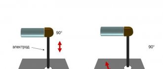
Such welding techniques can be performed qualitatively only if the angle of the electrode is initially correctly set in relation to the metal surface and the direction of welding.
Types of spatial welding positions
Bottom horizontal position. The most convenient position for obtaining a high-quality seam of any complexity. This is accompanied by gravity, which transfers the molten metal into the weld pool and a comfortable position for observing the welding process.
Vertical position. Gravity prevents the precise transfer of molten metal, so welding in this position has a number of features. It must be performed with a short arc and be sure to hold the electrode at an angle and quickly withdraw it to harden the metal.
Welding vertical seams is performed in two ways:
- "Down up". A more convenient method, which is based on holding a liquid drop of metal above a previous drop that has already hardened.
- "Top down". An inconvenient method, but used for welding thin metals. The electrode is positioned at an angle of 900 and gradually moves at an angle of 10-15°, and the arc is directed towards the molten metal.
Ceiling position of the seam. The most difficult position for making a weld, therefore it is only possible with a small amount of metal in the weld pool. When making a seam in this position, less current is used, a short arc is maintained and a narrow seam bead is formed.