Quite often, to build a welding inverter, the main three types of high-frequency converters are used, namely converters connected according to the following circuits: asymmetric or oblique bridge, half-bridge, and full bridge. In this case, resonant converters are subtypes of half-bridge and full-bridge circuits. According to the control system, these devices can be divided into: PWM (pulse width modulation), PFM (frequency control), phase control, and there may also be combinations of all three systems.
All of the above converters have their pros and cons. Let's deal with each one separately.
Half bridge system with PWM
The block diagram is shown below:
This is perhaps one of the simplest, but no less reliable push-pull converters. The “surge” of the voltage of the primary winding of the power transformer will be equal to half the supply voltage - this is a drawback of this circuit. But if you look from the other side, you can use a transformer with a smaller core without fear of entering the saturation zone, which is also a plus. For welding inverters with a power of about 2-3 kW, such a power module is quite promising.
Since power transistors operate in hard switching mode, drivers must be installed for their normal operation. This is due to the fact that when operating in this mode, transistors require a high-quality control signal. It is also necessary to have a no-current pause in order to prevent the simultaneous opening of transistors, which will result in the failure of the latter.
Resonant half bridge
A rather promising view of a half-bridge converter, its circuit is shown below:
A resonant half bridge will be a little simpler than a PWM half bridge. This is due to the presence of resonant inductance, which limits the maximum current of transistors, and switching of transistors occurs at zero current or voltage. The current flowing through the power circuit will be in the form of a sinusoid, which will remove the load from the capacitor filters. With this design of the circuit, drivers are not necessarily needed; switching can be carried out by a conventional pulse transformer. The quality of control pulses in this circuit is not as significant as in the previous one, but there should still be a no-current pause.
In this case, it is possible to do without current protection, and the shape of the current-voltage characteristic of the current-voltage characteristic will have a falling form, which does not require its parametric formation.
The output current will be limited only by the magnetizing inductance of the transformer and, accordingly, can reach quite significant values in the event that a short circuit occurs. This property has a positive effect on the ignition and burning of the arc, but it also must be taken into account when selecting output diodes.
Typically, the output parameters are adjusted by changing the frequency. But phase regulation also provides some advantages and is more promising for welding inverters. It allows you to bypass such an unpleasant phenomenon as the coincidence of a short circuit with resonance, and also increases the range of regulation of output parameters. The use of phase control can allow the output current to be varied in the range from 0 to Imax.
Asymmetrical or oblique bridge
This is a single-ended, forward-flow converter, the block diagram of which is given below:
This type of converter is quite popular both among ordinary radio amateurs and among manufacturers of welding inverters. The very first welding inverters were built precisely according to such schemes - an asymmetric or “oblique” bridge. Noise immunity, a fairly wide range of output current regulation, reliability and simplicity - all these qualities still attract manufacturers to this day.
Quite high currents passing through transistors, an increased requirement for the quality of the control pulse, which leads to the need to use powerful drivers to control transistors, and high requirements for installation work in these devices and the presence of large pulse currents, which in turn increase the requirements for capacitors filters are significant disadvantages of this type of converter. Also, to maintain normal operation of the transistors, it is necessary to add RCD chains - snubbers.
But despite the above disadvantages and the low efficiency of the device, an asymmetric or “oblique” bridge is still used in welding inverters. In this case, transistors T1 and T2 will operate in phase, that is, they will close and open simultaneously. In this case, energy accumulation will occur not in the transformer, but in the inductor coil Dr1. That is why, in order to obtain the same power with a bridge converter, double the current through the transistors is required, since the duty cycle will not exceed 50%. We will consider this system in more detail in the following articles.
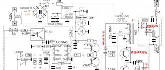
Control block
Diagram of the control unit for a full-bridge welding inverter
……….The control unit is built on the basis of the common TL494 PWM controller using one regulation channel. This channel stabilizes the current in the arc. The current setting is generated by the microcontroller using the CCP1 module in PWM mode at a frequency of approximately 75 kHz. The PWM filling will determine the voltage across capacitor C1. The magnitude of this voltage determines the magnitude of the welding current. ……….The inverter is also blocked using the microcontroller. If a high logic level is applied to the DT(4) input of the TL494, the pulses at the Out output will disappear and the inverter will stop. The appearance of a logical zero at the RA4 output of the microcontroller will lead to a smooth start of the inverter, that is, to a gradual increase in the filling of pulses at the Out output to the maximum. Inverter blocking is used at the moment of switching on and when the temperature of the radiators is exceeded. This is what happened in hardware. Power supplies, drivers and control unit on one board.
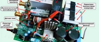
.In my device, the indicator and keyboard are connected to the control unit via a computer cable. The loop passes in close proximity to the radiators of the keys and the transformer. In its pure form, such a design led to false pressing of the keys. I had to use the following special ones. measures. The cable has a ferrite ring K28x16x9. The train is twisted (as far as its length allows). For the keyboard and thermostats, additional 1.8K pull-up resistors were used, shunted by 100 pF ceramic capacitors. This circuit design ensured that the keyboard was noise-resistant and false key presses were completely eliminated. ……….Although, my opinion is that interference should be prevented into the control unit. To do this, the control unit must be separated from the power part by a solid metal sheet.
Full bridge with PWM
It is a classic push-pull converter, the block diagram of which is shown below:
This circuit allows you to receive power 2 times more than when turning on the half-bridge type and 2 times more than when turning on the “oblique” bridge type, while the magnitudes of the currents and, accordingly, losses in all three cases will be equal. This can be explained by the fact that the supply voltage will be equal to the “drive” voltage of the primary winding of the power transformer.
In order to obtain the same power with a half-bridge (drive voltage 0.5 Usupply), the current required is 2 times! less than for the half-bridge case. In a full bridge circuit with PWM, the transistors will operate alternately - T1, T3 are on, and T2, T4 are off and, accordingly, vice versa when the polarity changes. Through a current transformer, the values of the amplitude current flowing through this diagonal are monitored and controlled. To regulate it, there are two most commonly used methods:
- Leave the cut-off voltage unchanged, and change only the length of the control pulse;
- Change the cut-off voltage level according to data from the current transformer while leaving the duration of the control pulse unchanged;
Both methods can allow changes in the output current within fairly large limits. A full bridge with PWM has the same disadvantages and requirements as a half bridge with PWM. (See above).
Inverter setup
The power section is still de-energized. We connect the previously tested power supply to the control unit and plug it into the network. All eights with a dot in the least significant digit will light up on the indicator. We connect the oscilloscope to wires Out1 and Out2. We control the presence of bipolar pulses with a frequency of 40-50 kHz with a dead time interval of at least 1.5 μs between them. The dead time value can be adjusted by changing the voltage at the DT(4) input of the TL494. After this, you need to check the voltage at the gates of the keys with an oscilloscope. There should be rectangular pulses with rises of no more than 500 ns, a frequency of 40-50 kHz and an amplitude of 15-18 V. If everything is so, we assemble the entire inverter circuit and connect it to the network. The eights will first be displayed on the display, then the relay should turn on and the indicator will show 120 A. If the eights continue to light, then the voltage in the welding wires does not exceed 100 V. We look for the cause and eliminate it. If everything is so, then by clicking the buttons we try to change the current setting. If you hold down one of the buttons, the current setting will change automatically. Changing the current setting should proportionally change the voltage on capacitor C1. Click both buttons at the same time. Switch to temperature display mode. If the temperature readings are not correct, then by selecting the resistance of resistor R2, we achieve accurate readings. If everything is so, we set the task to 20 A and connect a load rheostat with a resistance of 0.5 Ohm to the welding wires. The rheostat must withstand the flow of a current of at least 60 A. We connect a voltmeter of the magnetoelectric system with a scale of 75 mV to the shunt terminals, for example the Ts 4380 device. On a loaded inverter we try change the current setting and control the current using the voltmeter readings. The current must vary in proportion to the reference. We set the current setting to 50 A. If the voltmeter readings do not correspond to 50 A, then with the inverter turned off, we solder resistance R3 of a different value. By selecting resistance R3, we ensure that the current setting corresponds to the measured one. If everything is so, you can try to weld, after 1 minute of welding with a current of 120 A, turn off the inverter from the network and look for the hottest radiator. A temperature sensor must be installed in this radiator.
Resonance Bridge
It is the most promising high-frequency converter circuit for a welding inverter, the block diagram of which is shown below:
A resonant bridge is not much different from a full PWM bridge. The difference is that with a resonant connection, a resonant LC circuit is connected in series with the transformer winding. However, its appearance radically changes the process of power transfer. Losses will decrease, efficiency will increase, the load on input electrolytes will decrease and electromagnetic interference will decrease. In this case, drivers for power transistors should be used only if MOSFET transistors are used that have a gate capacitance of more than 5000 pF. IGBTs can only get by with a pulse transformer. More detailed descriptions of the schemes will be given in subsequent articles.
The output current can be controlled in two ways - frequency and phase. Both of these methods were described in a resonant half-bridge (see above).
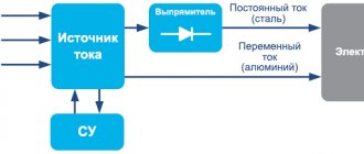
Application
The half-bridge circuit is best suited for relatively low-power (up to 500 W) power supplies with a high-voltage input and a low-voltage output. Most computer power supplies and pulse chargers are built according to this scheme. An example would be the following charger. The use of a half-bridge circuit at a low input voltage is limited by the fact that in this case high losses on the power switches are obtained, and high-capacity capacitors C10, C11 are needed, designed for high currents.
Full bridge with dissipation choke
Its circuit is practically no different from the circuit of a resonant bridge or half-bridge, only instead of a resonant LC circuit, a non-resonant LC circuit is connected in series with the transformer. Capacitance C, approximately C≈22μF x 63V, works as a balancing capacitor, and the inductive reactance of the inductor L as a reactance, the value of which will change linearly depending on the change in frequency. The converter is controlled by frequency. As we know from electrical engineering, as the voltage frequency increases, the inductance resistance will increase, which will reduce the current in the power transformer. Quite a simple and reliable method. Therefore, a fairly large number of industrial inverters are built according to this principle of limiting output parameters.