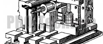
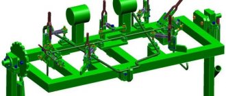
Homemade or factory-made welding fixtures hold metal structural components in position and improve positioning accuracy. Equipment is necessary when performing basic and additional steps of the technological process. In serial or mass production, automatic devices are used. In domestic conditions, mechanically driven products are used.
Welding fixtures are needed to provide the most favorable working conditions.
Types of welding equipment
When carrying out welding work, a transformer or inverter is required, connected to an alternating current network with a voltage of 220 or 380 V.
Since the parts are displaced during the joining process and heated to temperatures above +200°C, equipment is required to position and hold the workpieces. Assistive devices are usually divided into categories based on functionality, performance and principle of operation.
By functionality
Equipment can be:
- Universal, designed to work with workpieces of different designs or geometric configurations. It is characterized by reduced dimensions and weight, and is used when checking the correctness of assembly and installation dimensions, as well as when carrying out repair work. Does not provide high performance. Universal devices include clamps or spring clamps.
- Special, designed to perform one operation or used for welding assemblies with uniform design characteristics. Used in large-scale production, it improves quality and reduces welding time. Special equipment includes assembly and welding stands, jigs or templates.
By type of production
The equipment is divided:
- For serial or mass production. It has an increased service life and ensures faster removal and installation of workpieces. The stops are adjustable for the production of metal structures of various configurations.
- For single or small-scale production. Used at home or for welding experimental units. It is not demanding on the speed of installation or removal of workpieces; it is designed for the production of several dozen welded assemblies.
Equipment is divided by type of production.
By nature of work
Equipment is divided into the following types:
- with a manual drive (for example, with a screw or spring clamp or an eccentric);
- mechanized (with power hydraulic or pneumatic cylinders or electric drives), operating under operator control;
- automated (equipped with a mechanical drive and actuator units, the welder needs to configure the sequence of actions and confirm the start of work).
In addition to equipment that operates at standard speed, there is equipment with increased speed that speeds up technological processes.
For mass production, multi-position or carousel-type equipment is used, which reduces the time for installing and removing workpieces.
Devices can be transported or installed on foundations (rigidly fixed in place or moved along guides).
Do-it-yourself welding fixtures - clamp
Making welding fixtures with your own hands is quite simple. Many craftsmen actively use homemade designs, as they are more comfortable to use. In addition, some magazine versions are characterized by low reliability; too high a load leads to deformation and damage.
DIY clamp
To create universal welding fixtures you may need:
- Nuts that are designed for possible load.
- Sheets of metal about 10 mm thick.
- Large diameter washer.
- A pipe-type blank with an external thread that fits the selected nut.
It is worth considering that when using ordinary metal, corrosion will appear on the surface over time. That is why it is necessary to provide for the peculiarities of the process of coating steel with a special anti-corrosion composition.
Equipment requirements
The equipment used when welding parts must provide:
- Changing the position of the part within the welded unit without the adjustment operation.
- Fast and reliable placement of workpieces in fixtures.
- Maintaining assembly accuracy within the tolerances specified in the design documentation.
- Unobstructed access to welds and parts connection lines.
- Compliance with the dimensions between the ends of the elements being welded.
- Work safety. The equipment is made from materials that are resistant to high temperatures; the application of flammable coatings is not permitted.
- Welding in the lower position to prevent the melt from flowing out of the bath.
- Accelerated heat removal from the working area.
- Protection of moving elements and actuator cylinders from splashes of molten metal and flux.
- Reduced deformation in welding seams.
- Possibility of automating the technological process or mechanizing the transportation of blanks or finished products.
The equipment ensures a change in the position of the part within the welded unit.
Requirements for welding equipment and its design
From the point of view of the technological process of manufacturing welded structures, assembly and welding equipment has the following advantages:
- ensures high quality of welded parts and their compliance with specified technical parameters;
- simplifies the assembly and welding process;
- reduces labor intensity and increases productivity;
- prevents or reduces the proportion of deformations during the welding process.
Often, such devices are part of welding installations and are built into in-line mechanized and automated lines. It is important that with the help of technological equipment it is possible to mechanize and automate not only the main, but also auxiliary operations.
Thanks to assembly and welding equipment, it is even possible to solve some social issues. Thus, with the help of such devices, it becomes possible to refuse or significantly reduce the share of heavy or unproductive labor. As a result, the safest working conditions for employees are achieved.
It is worth noting that there is also a large selection of auxiliary equipment designed for carrying out large-scale welding work. The type of devices used is selected according to the design of the unit being welded; the nature of production and the method of carrying out the thermal process are also taken into account.
Modern semi-automatic welding machines are used in mass production and require repeatable processes, while machines for manual arc welding are suitable for joining various individual products. Due to the competent choice of design and type of welding equipment, it is possible to significantly increase the level of mechanization and productivity of work, as well as reduce operating costs.
Of course, equipment is not a determining factor when choosing welding equipment, but its development and use play an important role in welding, especially on a production scale.
Let us name the requirements for assembly and welding equipment:
- Precise spatial placement of parts, including multi-component assemblies, which eliminates the need for manual adjustment.
- Easy access to all elements of the product for tacking, stripping and applying main welds.
- Assembly in accordance with the tolerances established by the design documentation, that is, drawings, technical specifications.
- Compliance with the inter-edge dimensions of fastened elements.
- Optimal assembly order, increased productivity, the ability to obtain high-quality seams.
- Safety of use even during emergency situations - disassembly of the unit, failure of fixing devices, etc.
For large-scale and similar work, power clamping hydraulic, pneumatic or mechanical (screw) devices are often used. Since it is very important to avoid spontaneous release of the welded element, self-braking links are usually included in the kinematic diagram of pneumatic and hydraulic equipment.
If you plan to use cam clamps, you should consider protecting them from molten metal splashes in advance. The fact is that even a few drops are enough to disable such mechanisms, despite the fact that modern semi-automatic welding machines have a low level of spattering of electrode and product materials.
There are also a number of additional requirements for assembly and welding equipment:
- Possibility of welding invariance , that is, work in the lower and vertical positions at different angles of inclination.
- Fast heat dissipation , especially when it comes to highly focused, intense welding. In this case, you can purchase inexpensive but high-quality welding equipment “Svarog” and other budget inverters.
- Protection of base welded surfaces and equipment elements from the ingress and adhesion of metal splashes.
- Minimal deformation under the influence of temperature in the joint being connected.
- Rigidity, strength, long service life of the structure.
- Possibility of normal removal without jamming of clamps , stops and templates of welding equipment after completion of work.
During engineering calculations, it is necessary to take into account the degree of expansion of materials when heated. Equipment can be considered high quality if reliable fixation is combined with the possibility of displacement of the welded products. The fact is that too rigid fastening increases shrinkage and temperature stress, that is, leads to cracking and various types of deformation in the welding assembly.
If we are talking about welding on an industrial scale, the development of welding equipment must be carried out in accordance with the technical specifications. The latter includes:
- Drawings of connected units with a detailed description of the assembly and welding process. All schemes must be tested in practice.
- Type of device according to operating principle : lifting, stationary, rotary, lifting and rotating, mixed.
- Locations of clamping and fixing elements , as well as their type, design, force developed, and other details.
- Connection diagrams for all communications necessary in this case , the presence of ventilation, operating pressure in hydraulic systems, pneumatic and electrical networks.
- Operating modes, timing of maintenance, replacement of consumables.
- Methods for loading/removing elements held together by welding, and other information regarding the inclusion of welding equipment in the chain of production processes.
Without auxiliary equipment, the functionality and productivity of modern semi-automatic welding machines, automated and robotic welding complexes is significantly reduced.
Development of equipment involves the following sequence of actions:
- Spatial modeling of the assembled unit and each part separately.
- Preparation of a basic diagram, which indicates the reference, overall, and installation dimensions.
- Creation of equipment drawings with all auxiliary, clamping elements, control, overall dimensions, requirements for dimensional accuracy.
- Inclusion of the project in the technological chain, which, first of all, involves its introduction into the system of interoperational transportation of finished products.
Calculation of clamping/fixing forces is made depending on thermal deformation during operation, parameters of power cables and other infrastructure features. So, if one-time welding of rotary joints is carried out, the operation of the welding heads must begin simultaneously, and the electrical circuit is supplemented with a welding discharge excitation synchronization unit. As soon as an accidental arc extinguishing occurs even in one of the installations, the electronics stops the operation of the entire complex.
If you buy welding equipment only for home needs, then complex design and manufacture of welding equipment is not required. In this case, the equipment consists of welding several angles from ordinary reinforcement. Although often, in order to weld a steel sheet to a gate or a loop to an iron gate, no auxiliary means are required at all.
In medium-sized enterprises, additional equipment for workplaces can significantly increase the productivity of welding equipment. In large productions, separate departments, such as tool shops, design bureaus, etc., are responsible for the development and implementation of equipment. Whereas it is possible to improve medium-level production even without major capital investments.
Standardization of technological equipment for a welding table is a proven way to increase labor productivity, which also allows you to increase such indicators as the manufacturability of labor and the utilization rate of welding equipment. The type and standard sizes of equipment are selected in accordance with the specifics of the activities of a particular enterprise.
Today you can contact specialized companies that develop turnkey welding equipment - they provide a guarantee for its full functioning. Services of this nature can be the best solution for medium-sized enterprises, because in this case it is possible to obtain noticeable results with small investments, saving your own material resources and time.
Assembly and welding devices
They are divided into the following categories:
- Installation, allowing the positioning of parts in accordance with the drawing documentation. Depending on the configuration of the workpieces, the products have vertical, horizontal or inclined edges. The devices are rigidly attached to the base, moved along guide grooves or tilted to the side on an axis or hinges. Permanent profile stops are welded or screwed to the welding table. Adjustable brackets are used for parts with uneven geometry.
- Fixing or fastening devices that prevent parts from moving during the welding process (for example, due to temperature deformation or accidental exposure to the electrode). Welders use clamps with a lead screw or cam mechanism. To assemble a metal structure, you must have a set of clamping devices (the size of the pharynx is determined by the dimensions of the workpieces).
Ties
The coupler is a threaded bushing that allows you to adjust the distance between the mating edges. To install a bolt, brackets with nuts or holes with threads inside are temporarily installed on the parts.
We recommend reading: How to make an oscillator yourself
For example, a welding square is used when connecting pipes made of carbon steel. There are couplers with clamps that are placed on the outer surface of cylindrical parts and secured with screws. The design does not provide rigid fastening of the parts to be connected.
Tacks
A clamp is a small piece of reinforcement or steel profile that is used to temporarily connect large parts.
To change the position of the parts, adjustable elements (with a threaded bushing) are used.
After filling the joint with molten metal, the clamps are cut off or integrated into the structure of the seam.
Jacks and spacers
Rack jacks and rods with a screw section are necessary for holding metal structural elements with a closed profile and for aligning the mating edges of cylindrical workpieces.
The devices are used to straighten dents on the surface. When connecting pipes, spacers are used in conjunction with external clamping rings, which increases the accuracy of the joints.
Jacks can be equipped with a mechanical drive.
There are products with hydraulic or pneumatic cylinders connected to an external pump or compressor station.
Centralizers
If, when welding workpieces that have an axis of rotation, it is necessary to hold the parts in 3 planes, then centralizers are used. They allow you to align the outer surfaces and the center line.
Workpieces are held by gripping the outer or inner parts. The equipment has a mechanical drive of the executive body. Centralizers for large-sized pipes are equipped with hydraulic cylinders.
Brief description of the operation of the centralizer TsNG-1120:
- Align adjacent sections of the pipeline.
- Place a double roller chain on the joint line.
- Connect the hydraulic drive to an external pumping station with a spool valve.
- Turn on the fluid supply and wait for the outer edges to align evenly.
- Weld the seam through the gap between the chain sections.
- Release the force and then move the device to the next joint line.
Centralizers hold parts in 3 planes.
Universal fixtures for welding assembly
Universal assembly devices are usually simple and portable. They do not always provide the necessary accuracy and are designed to verify correct assembly and installation dimensions.
Portable clamps are designed to fix the relative position of the parts to be welded. Clamping fixtures can be used when welding certain parts, as well as in the manufacture of assemblies and structures. In this case, they are equipped with stands, racks and other auxiliary equipment. They are made in the form of clamps and bolt clamps, allowing you to assemble parts of any profile.
Wedges and clamping brackets are used to assemble rolled sheet products for welding. Spring clamps are used to secure thin sheets and short parts made of rolled profiles.
| wedge bracket | clip | spring clip |
Clamps are used mainly when installing large structures. Individual elements of the clamps are temporarily welded to the assembled parts, and after welding they are removed. Clamps are rigid and adjustable.
Ties are used to bring the edges of welded parts together to specified sizes. Screw ties are the most widespread.
Tie with bolt and welded angles for welding large structures made of sheet metal.
Tensioning device with welded temporary elbows for pipe assembly. It is used to a limited extent and only on carbon steel pipes.
Screw coupler for assembling structures and parts from sheet, strip and profile products.
Lever-screw coupler.
For assembling pipe joints, clamp-type clamping screw devices are most commonly used, which do not create a rigid fastening of the joined elements.
Spacers and jacks are used to fix products with a closed profile from the inside, to align the edges of cylindrical products, to remove dents, etc. When welding cylindrical products, spacers are used in combination with clamping rings. If the diameter of the shells is small, spacer rings are used, and for larger diameters, screw spacers or jacks are used. The forces in spacers and jacks are created by mechanical, hydraulic or pneumatic drives.
Centralizers are designed to secure individual pipes or similar products so that they do not shift or rotate in the directions of three coordinate axes. They allow you to combine the cylindrical surfaces of joined products (pipes, sections of pipes, etc.) to perform welding work. Depending on the position of the centralizers relative to the mounting surfaces, centralizers are divided into external (grasping) and internal (spacer). External centralizers are used when assembling pipes into sections for welding at procurement bases or in the area of construction sites. Although the design of external centralizers is different, they perform one operation to ensure alignment and alignment of the end edges of the pipes (see figure below).
| Pliers for pipes up to 40 mm in diameter | Screw clamp device for pipes up to 60 mm in diameter |
Centralizers for assembling large-diameter pipes can be equipped with a hydraulic power cylinder in the place of the clamping screw. The external hydraulic centralizer is a double-row plate chain, tightened at the ends of the joined pipes with a jack placed inside the bracket. The jack is driven by a hydraulic pump station.
External hydraulic centralizer TsNG-1220 1 - chain; 2 - thrust roller; 3 — staples; 4 - end link; 5 - jack; 6 - screw.
Internal centralizers provide the highest quality pipe assembly due to a more accurate alignment of their edges. When centering, the joint is open from the outside, which provides free access to the welding site. The use of internal centralizers makes it possible to increase the productivity and degree of assembly mechanization for welding both rotary and non-rotary pipeline joints.
Stands for welding and assembly
Several types of stands are used to connect parts:
- flat slabs;
- racking systems for the production of volumetric metal structures;
- conductors and templates;
- devices for holding parts in the required position during welding.
Shelving and slabs
To connect flat workpieces, plates assembled from sections of steel profile are used. The top edge of the guides forms a flat surface. The parts are fixed using replaceable or rigidly attached stops to the base.
Equipment is divided into stationary, portable and overhead (installed on work tables or beds). The rack is distinguished by the use of inclined surfaces with replaceable supports. It is made of a steel profile that allows you to connect power from a welding transformer.
Algorithm for using a rack when welding a T-shaped beam from flat workpieces:
- Place the stops in the required position and install the elements at the required angle.
- Go through the joint line with a welding tractor or semi-automatic machine.
- Turn the structure over and sew the seam on the other side.
Conductors
The device consists of a frame (with stops and fasteners) mounted on a swinging axis. The jig allows you to install parts in the required position.
The operator then welds the metal structure, changing the installation angle. A device is provided to hold a bath of molten metal and flux in the work area. This allows you to get a strong seam without tears or internal voids.
Adjustable stops are used on the conductors; it is possible to use a welding tractor to automate the assembly process.
In this case, auxiliary components should not interfere with the movement of the equipment.
The tilt angle can be changed manually or electrically. The equipment is used in the serial production of welded structures. In artisanal conditions, conductors are rare.
Fasteners
To firmly hold metal structure parts in a given position, removable or stationary clamps are used, which have different configurations and methods of attachment to the desktop.
Clamps are needed to firmly hold parts.
For example, in the manufacture of products, removable brackets are used to take into account differences in the geometric dimensions of the workpieces.
To connect parts to machined surfaces, rigidly fixed or adjustable prisms are used, and for mass production, a reusable template is installed on the table, defining the outline of the welded structure.
Templates
They are rigidly installed guides that hold several parts in the required position. After welding, the resulting assembly is removed for machining or installation of additional elements using other equipment. Since the cost of manufacturing a template is higher than that of adjustable stops, the technology is used in mass production or for welding individual non-standard structures (the price of the equipment is included in the price of the product).
Stops
Folding or fixed stops keep parts from moving to the side; units are used in jigs and on shelving. Stops are usually divided into limiting (or force) and guides (they do not experience load from the weight of the parts). The brackets are installed with screws (with the ability to move along grooves cut in the base) or welded to the rack.
Stops keep parts from moving.
Clamps
Pressure plates are designed to hold flat or shaped workpieces and have a mechanical or power drive (hydraulic, electromagnetic or pneumatic).
We recommend reading: How to install a hood above a welding table
The manual device consists of a bracket (welded to the base or moving along a guide slot) and a screw with a handle. After installing the workpieces, the operator tightens the clamp and begins welding.
Devices with a spring-loaded rod or with a rotating eccentric head mounted on a bracket have become widespread.
Assembly and welding stands
Stands, racks and plates are the simplest devices for laying and fixing products assembled for welding in a position convenient for welding.
Assembly and welding rack
Assembly stands are structures with a base surface on which products are assembled and welded. When manual welding, universal assembly and welding plates with grooves for various fastening devices or racks are often used.
Stands and devices that combine assembly and welding operations can be stationary, mobile, or overhead.
Various beams are assembled and welded on the trestles of such a rack, installed at a short distance from each other along the entire length, or on a universal stand consisting of a number of fixed posts 2, to which, depending on the configuration of the beam, replaceable supports 1 are attached.
Scheme of a universal stand for welding beams: 1 - support; 2 - stand; 3 - welding tractor.
The listed stands refer to clampless devices. These include tables for welding relatively small parts and plates. A stand or table is usually connected to the arc power source and provides current supply to the product being welded.
If the product is supplied to the welding installation in assembled form, then this installation must have devices for laying and fixing the products in a position convenient for welding. In such cases, universal or specialized stands can be used. A universal device for welding frame structures contains a number of plates with grooves into which, depending on the configuration of the product being welded, various stops, clamps and clamps are attached. Such stands are equipped with a set of universal adjustment devices that can be fixed in various combinations in the grooves of the base plates. For assembly and welding of similar structures, specialized stands for certain products can also be used. They are equipped with a plate on which a number of permanent clamps are mounted, which determine the relative position of the parts assembled for welding. An example of universal stands for assembly and welding of flat sheet structures are electromagnetic stands. Electromagnetic stands can be used to assemble and weld sheets up to 15 mm thick. The disadvantage of this type of device is the negative influence of the magnetic field on the welding arc during the welding process.
A jig is an assembly and welding device equipped with stops, sockets, and fastening devices, which makes it possible to assemble and weld products in the most convenient position. In addition, the stands and devices include devices for holding a bath of molten metal and flux in the welding zone, for forming a sha, etc. Mechanized welding is most often performed in assembly-welding or welding jigs. In these devices, the conductor elements do not interfere with the movement of the welding machine; the jig itself can tilt, giving the seam a position convenient for automatic welding.
Examples of assembly and welding conductors
Clamps are elements that determine the position of the parts being welded relative to the entire device (stand, rack, conductor, etc.). The clamps include: stops (permanent, removable, folding), mounting pins and pins (permanent, removable), prisms (rigid and adjustable) and templates.
Removable stops are used in fixtures that can be adjusted according to the type of part or when welding parts that cannot be removed due to the stops. In the latter case, folding quick-release stops deserve preference. As a rule, stops also serve as support bases, and in some cases they can simultaneously serve as templates for welding mating parts. They can be force (limiting) and guiding (unloaded).
| The emphasis is hard | Removable stop | Folding stop |
Finger or pin type fasteners Prisms, adjustable and non-adjustable, are used for welding pipes, profiles, etc.
| Finger hard | Adjustable prism | Flip finger |
Templates are designed for; fixing the parts installed during assembly along the mating parts of the assembly or along any supporting contours of the products. In this case, the product itself is the load-bearing element of the device.
Clamps are elements of devices that provide clamping of parts to each other, to clamps or load-bearing surfaces of devices. Clamps can be mechanical, pneumatic, hydraulic or magnetic.
Mechanical clamps are structurally simple and therefore most common.
| Screw clamps | Eccentric clamp | Spring clamp |
Along with mechanical clamps, pneumatic, hydraulic and magnetic clamps are also used.
Equipment for installations
Welding installations use additional technological equipment:
- Baths for holding molten flux, preventing the penetration of foreign impurities into the metal, reducing the strength of the joint. Used when it is impossible to protect the weld using standard methods. For example, when welding vertical sheets with an overlap, a corner is installed that does not allow liquid flux to flow down the surface. Baths can be mobile or stationary.
- Flux pads that prevent molten metal from flowing out through the gap between the sheets. The protective layer is pressed against the lower edge of the workpiece, holds the weld pool and forms a reverse seam bead.
Laying and edging of products
When welding large-sized workpieces, it becomes necessary to rotate and move the assembled unit. There are roller-type and lantern-type tilters.
There are installations with levers or chain grips. The parts are fixed in a given position using manual or mechanical drives, after which the operator begins to weld the seams.
The equipment is equipped with fixed or adjustable stops and clamps, and universal manipulators are produced that allow you to work with workpieces of different sizes.
Roller beds
Roller machines are designed for welding cylindrical elements. The wheels are equipped with a rubberized rim to improve contact. One of the rollers is power driven by an electric motor or manual gearbox; the remaining supports are necessary for positioning the parts in space.
Roller beds are designed for welding cylindrical parts.
To connect conical blanks, the bases of the rollers are equipped with regulators necessary to change the angle of the wheels.
Rotators for products
A rotator (or carousel) consists of a work table with a vertical, inclined or horizontal axis that does not change its position in space. The workpieces are mounted on the surface using clamps; the rotation speed depends on the welding speed and the characteristics of the technological process. To drive the rotary unit, electric motors with gearboxes and hydraulic motors are used (rotation speed depends on fluid pressure).
Universal manipulators
To position welded structures in the industrial cycle, universal stationary equipment is used, equipped with a cast or welded frame with rigid attachment to the foundation slab. Inside the frame there are electric drives, a transformer and mechanisms for supplying inert gas and filler wire. The workpieces are placed on a work table or faceplate with dovetail grooves intended for mounting stops or clamps.
Universal manipulators are used to position welded structures.
The faceplate is equipped with sectors with gear rims and is mounted on a hinge that allows table deflection. Some manipulators are equipped with a surface height adjustment system. There are budget manipulators with manual control used for small-scale production.
Positioners for edging
Designed to rotate installed workpieces into a position that provides access for the electrode or welding head to the joint line. The equipment consists of a frame and a manipulator with a manual, electric or hydraulic drive. The parts are mounted on the surface of a faceplate, which can be rotated in several directions (manually or according to a stored program).
A standard positioner can move the weld assembly around an axis to weld parts along the top and bottom surfaces, and also raise and lower the product to fill joints on the sides with metal. Manual units are equipped with gearboxes with stoppers that reduce the load on the operator during operation. When the mass of workpieces is more than 1500 kg, an electric drive with a constant speed of movement is used (no movement speed controllers are provided; the seam is performed by moving the electrode or head along the line of connection of the parts).
Assembly using various devices
Assembly of metal structures
Assembling metal structures is a labor-intensive operation that requires great precision, especially when assembling lattice structures. Structures are assembled according to KMD detail drawings or technological drawings of metal structures on racks or assembly stands.
Rice. 41. Mobile stand made of trestles
Mobile stands (Fig. 41) are used in the manufacture of metal structures with low repeatability. They consist of trestles that are installed in channels concreted in the floor. Tragus come with two or three supports. The height of the trestles from the floor is 650 mm with a permissible height deviation of ±3 mm from the general level, the length is 2.5 or 4.5 m, the distance between the trestles is 1.5–2 m. The assembled structure is placed on several trestles at once.
On trestles, metal structures are assembled according to markings, assembled according to a copier, and simply assembled the structure of trusses, columns, shelves, trestles and non-standardized equipment.
For the assembly and welding of metal structures, universal stands are used (Fig. 42). The stand has a number of movable rods as the main reference plane. Each rod has a longitudinal groove for attaching replaceable parts (stops, clamps, clamps, etc.) anywhere along the length of the rod.
The rod can move along the guides and be fixed anywhere with a clamping bolt. When moving the rod along the guides, it is possible to attach replaceable parts at any given location on the base plane.
Rice. 42. Universal stand for assembly and welding of metal structures: 1 - guides; 2 - movable rods; 3 — place for attaching the rods to the frame; 4- clamps
The stand is a frame of a welded structure made of channels. Three guides are installed on the frame, each of which consists of two paired channels.
There are eleven movable rods on the guides, each of which is welded from two corners. After their manufacture, the upper and lower planes of the rods are aligned and, if necessary, processed to make the entire stand horizontal.
At the stand you can assemble welded structures such as frames and flat trusses, as well as non-standardized equipment of small sizes. If it is necessary to manufacture parts of longer length, two stands are connected together.
When assembling technological metal structures, assemblers use measuring and assembly tools, as well as various devices. The measuring tool used is the same as for marking.
Assembly tools include crowbars, hammers and sledgehammers, chisels, wrenches, wedge staples, clamps, jacks, brushes and scrapers.
When assembling lattice spatial racks of small height, consisting of four branches connected by a lattice, assembly holes, as a rule, are not made. Two branches of racks are laid out on the rack and the grid is placed along them strictly according to a geometric pattern.
After this layout, the lattice is tacked to the branches. Then the second plane is assembled, and after that the two planes are connected to each other by a lattice. Assembly using this method cannot be considered accurate.
When manufacturing sheet technological metal structures, assembly accuracy is of great importance. The quality of the entire structure depends on this.
To level the plane of the assembled sheets, special devices are used - tie strips with rectangular holes (Fig. 43).
Rice. 43. Tension strips: 1 - tension sheet; 2 - rectangular washer; 3 - wedge
Rectangular washers are welded to the two assembled sheets. A tension sheet is placed on the rectangular washers. The sheets are leveled by driving wedges into the washers. The sheets are pulled together with a second pair of wedges, thereby providing the necessary gap between them for welding.
When assembling sheet structures, such as bunkers, tanks, furnace casings, tension gaskets are used (Fig. 44). A cylindrical rod is welded into one of the holes of the 2–4 mm thick strip, and a conical mandrel is inserted into the second, which serves to align the edges of the joined sheets.
Rice. 44. Tightening gaskets: 1 - strip; 2 - conical mandrel
In some cases, these two assembly devices are placed together on the sheets to be joined in such a way that there are one or two spacers with mandrels between the tie gaskets. Unnecessary fixtures are gradually removed during welding, and gaskets are pulled out of the gaps. If the gaskets cannot be pulled out, they are cut off.
The assembly of technological metal structures from rolled profiles is carried out in four ways: by marking, by copier, in jigs and using assembly devices.
Assembly according to markings
This assembly method involves installing and temporarily securing the assembled parts, the relative positions of which are determined by markings. This method is used when assembling single products.
Rice. 45. Beam with short pieces for welding located on it
The installed parts are secured with clamps or electric tacks and submitted for welding.
So, for example, when assembling an I-beam (Fig. 45), the location of the corners (for attaching to them when installing secondary beams) is marked from the holes. In this case, the size between the holes must be precisely maintained. The corners (short ones) are arranged according to size, but are not welded. Assembly work for this beam will involve electric welding of all corners.
Assembly "by copier"
This assembly method (Fig. 46) is used for flat truss structures. According to the markings, lay out the first half of the truss, i.e., the corners and gussets, on a flat surface. This part of the truss is strictly verified and remains a “copier” (Fig. 50, a). The second half of the truss is laid on it: first the gussets, then the corners (Fig. 50,b).
The corners are tacked to the gussets and then turned over to apply and tack the second corners (Fig. 50, c). The copier remained untouched. You can assemble the next farm in the same sequence. The “copier” method is especially convenient when producing a large number of trusses.
Rice. 46. Assembling a farm for a copier: a - assembled copier; b - half of the truss is laid out on the copier; c - half of the truss, removed from the copier and turned over; g - assembled farm
This method is very effective and is widely used in production. It does not require special devices. The assembly accuracy is quite sufficient, and complete identity of the assembled structures is guaranteed.
Assembly in jigs
Currently, metal structures factories use universal jigs, which have movable stops and clamps. The conductor itself is a rigid frame on which clamps and stops are located. One of the stops is made movable.
The assembly of inclined gallery bridges can be carried out both at the metal structures plant and at the installation site, depending on the dimensions of the bridge. Fundamentally, the assembly methods at the factory and at the installation site do not differ from each other.
Spatial lattice structures are assembled in the following sequence. Separate flat trusses, assembled “by pattern” or separately in jigs, arrive at the bridge assembly site welded. The trusses are installed in separate flat panels strictly vertically in size at a certain distance and temporarily secured. Lower beams are connected to the two installed trusses, which are immediately bolted or welded, depending on the design solution. After securing the main lower beams, ties are installed along the bottom of the bridge and secured.
In some cases, longitudinal beams are placed along the bottom of the bridge above the lower beams for attaching conveyors. After installing and securing all elements along the lower chord, they proceed to assembling the upper chord of the bridge. This sequence ensures free access of the crane to the structures of the lower chord of the bridge.
Assemble the upper chord of the bridge, starting with the beams and ending with the girders, if any. After assembling the structures at the bottom and top of the bridge, its spatial stability is checked. In some cases, the transverse frames of the bridge are referred to as supports (part of the support frames). They are prepared separately and do not provide the rigidity of the assembled bridge. In such cases, it is necessary to install temporary transverse ties to give the bridge spatial rigidity.
The described assembly is very simple. It is carried out at the installation site, when metal structures arrive from the factory for installation in bulk. When assembling, special attention is paid to the correct geometric dimensions, the placement of mounting holes and other elements on which the correct assembly or installation depends.
When assembling critical structures, where greater precision is required, assembly holes during the manufacture of parts are pierced or drilled to a smaller diameter.
During general assembly at the factory, the structure is assembled and aligned with temporary bolts. Then the holes are drilled to the designed diameter. After drilling, the structure is disassembled and sent for installation, having previously marked the sending elements and assemblies. At the installation site, the structure is assembled and permanent bolts are installed.
Holes are drilled using mobile radial drilling machines or hand-held pneumatic drilling machines.
To ensure the accuracy of assembly and welding of manufactured structures, metal structures factories and installation department workshops use various manipulators, rotators, tilters and roller stands.
Manipulators are used to rotate the welded products in any direction. The operating speed of rotation of the manipulator is equal to the speed of movement of the welding machine for welding in the lower position. Rotators are used to rotate welded parts and products around only one axis.
Rotators are designed for tilting (rotating) products into a position convenient for welding. They are single-post, two-post and ring. Roller stands are used to rotate products into a convenient position for welding and assembly. According to their purpose, they are divided into stands for welding cylindrical, conical and spherical surfaces, and according to their design - into driven and non-driven.
When manufacturing structures from pipes, the accuracy of the holes in the flanges is of great importance, since when connecting individual elements to each other, the holes must coincide.
A blank for a flange is made from a sheet by gas cutting on a gas cutting machine (automatic) SGU-1-60 using a metal template. After cutting, the parts are milled on both sides to maintain a right angle. When drilling holes on plane jigs, the milled sides of the part are used as a base to ensure the formation of holes with the required accuracy.
Rice. 47. Jig for drilling holes: 1 - flange; 2 — overhead conductor; 3 - bushing; 4 - bolt; 5 — special bolt; 6 — guide boss; 7 - lining; 8 — drilling machine bed
The overhead jig (Fig. 47) consists of the jig itself and bushings pressed into it. Using bolts, a guide boss is attached to the overhead jig, which fixes the flange being manufactured along the inner diameter. The flange from below is installed on a special lining and bolted to the lathe bed.
This jig allows you to drill holes in flanges with the required accuracy for welding or tacking flanges to pipes; various jigs are also used.
In the jig for installing flanges (Fig. 48), the flanges are welded (tacked) to the chords of the lattice truss. An adjustable stand is installed on the conductor frame, and on the other side there is a movable stand, capable of reciprocating movement.
The frame has sliding prisms that are adjustable in height. The installed elements are pressed tightly against the clamps using a movable stand, and then tack is performed.
Rice. 48. Jig for installing flanges: 1 - adjustable stand; 2 — universal clamp; 3 — sliding prism; 4 — movable stand; 5 — conductor frame
After tacking is completed, the assembled element is removed from the jig.
If spatial structures are assembled from the described elements, a special jig is used (Fig. 49). The operating principle of such a conductor is not much different from those previously described. The conductor stops are fixed in cast iron plates with grooves, to which the stops are attached using bolts.
Rice. 49. Stop-conductors for enlarged assembly of prisms: 1 - fixed stop-conductor; 2 — replaceable clamps; 3 - wedges; 4 - mandrels; 5 — adjustable stop-conductor; 6 - cast iron plate
Assembly using various devices
As already mentioned, various devices are used for the manufacture and assembly of similar elements. In Fig. Figure 50 shows a device (jig) for drilling groups of holes in the corners.
The device consists of a frame with a stop and adjustable supports on which clamping screws are fixed. Depending on the length of the processed corners, the adjustable supports can be rearranged. An overhead jig with jig bushings pressed into it is placed on top of the corners. Drilling is done on a drilling machine.
Rice. 50. Devices for drilling corners: 1 - frame; 2 - emphasis; 3 — overhead conductor; 4 — conductor bushing; 5 — clamping screw; 6 - processed corners
Beams of a composite section made of 3 sheets are classified as solid-wall structures. Such sections are used in columns, racks, crane beams and platform beams. There are also other sections of beams. Solid-wall structures are assembled in several ways (Fig. 51).
The simplest assembly method, which does not require special devices, is the method using assembly frames. After 1-1.5 m, short pieces are welded in a checkerboard pattern on the prepared sheet (belt) at a distance of half the wall thickness from the axis of the belt.
The prepared belt is laid in a horizontal position, and a wall with ribs welded to it is installed on it. The next sheet of belt is installed on top of the wall. To tightly connect all three sheets, several assembly frames are put on the beam, with the help of which the beam is tightened. After this, all sheets are electro-tacked. The assembled beam is submitted for welding. Instead of short pieces, you can use cuttings of channels, sheets, round steel, etc.
Rice. 51. Assembly of solid-wall structures using: a - fixing corners; b - short ones; c - staples and wedges
When assembling using shorts, shorts of any cross-section are welded to both chords (one side of the axis) at a distance of 600–700 mm from each other.
On the wall of the beam, located horizontally on supports, two belts with welded shorts are hung along the entire length. The short ones fix the position of the belts. Using assembly frames, the beam is pulled together, the sheets are grabbed, and the assembled element is sent for welding.
Both of these methods are imperfect, but applicable in any conditions, especially at the installation site in the manufacture of individual technological metal structures.
Currently, assembly using a bracket with a wedge is also used. With this method, the beam is assembled in a vertical position, and for tacking it is tightened with a bracket into which a wedge is driven. After the wedge is driven in, electrical sealing of the wall with shelves and ribs occurs. Then the staple is moved to a new place, and the operation is repeated.
Solid-wall structures are also assembled in conductors. Assembly jigs for such structures are either fixed or rotary. In fixed jigs, the beam remains tied motionlessly and does not rotate. In the second case, the beam can rotate about its longitudinal axis.
This makes it easier to position the electric tacks anywhere and allows for automatic welding of seams. Conductors are currently used in various designs. Each metal structures plant has a conductor of its own design.
Devices for rotation and fastening of equipment
In automatic or semi-automatic welding, special installations are used that allow the head with the electrode to be moved vertically or horizontally. The equipment consists of a rack and boom that are adjustable in size, and there are points for attaching power cables and hoses for supplying inert gas. The welding tractor moves along the surface of the parts to be joined in accordance with the program, but special trays or brackets are provided to hold the electrical wiring.
When welding, the head with the electrode moves automatically.
Work area equipment
Depends on the nature of the welding work performed and the size of the workpieces. For example, when welding large structures, knee lifts with a cradle for the operator and equipment are used. The units can move along guides or along the ground surface; for control, there is a remote control in the basket.
The drives are equipped with AC motors, some of the actuators are equipped with pneumatic or hydraulic cylinders.
In domestic conditions, a metal table is required, equipped with screens to protect against hot drops of metal and slag. They provide a chair for the welder and a set of devices for fixing parts. Work on flammable floor coverings is not permitted. The walls of the room are painted with light gray materials (to absorb the ultraviolet spectrum). Above the table there are lamps (lighting level from 80 Lux) and a hood with an electric fan (capacity 40 m³/hour).
We recommend reading Current regulator for a welding machine
Pipe welding devices
Pipeline welding equipment ensures the centering of mating products and maintains a uniform gap between the edges. There are devices for straight lines and corner branches. The design of the product includes clamps and additional clamps installed on movable rods or chains.
There are special devices for welding pipelines.
For example, to use a simple straight pipe device, the welder must:
- Move the workpieces with pre-prepared edges.
- Place clamps on the outer parts of the pipes and tighten the screws.
- Adjust the gap by rotating the bolt connecting the brackets to the clamps.
- Fill the joint with molten metal, and then remove the equipment and clean the surface of the joint from scale and slag.
Magnetic devices
For household and industrial welding, assembly and welding fixtures with permanent magnets are often used. For example, there are templates with surfaces located at different angles (fixed or variable). The products allow you to position sections of profile pipes or connect sheet steel workpieces. Magnetic clamps are not used when welding parts made of stainless steel or non-ferrous metals.
Universal equipment from MagTab or V-Pads is equipped with several surfaces with the ability to smoothly adjust their relative position. The operator needs to attach the product to the surfaces of the parts, ensure correct positioning, and then begin welding.
Equipment allows you to reduce the time spent on work and improve quality. The strength of the magnets ensures the immobility of the connected elements.
Auxiliary Tools
When welding parts, additional tools will be required:
- Hammers with a special striker and brushes with metal bristles, used to remove slag from the surface of the weld. To remove large fragments of flux and remove excess metal, use chisels.
- A measuring tool (square, tape measure, caliper) necessary for transferring drawing dimensions to workpieces. Lines are drawn with a marker, lump chalk or a metal rod with a pointed tip.
- Angle grinder with a protective casing and a set of discs for cutting metal, used when cutting workpieces. A hacksaw is used to cut profiles with a small cross-section. An electrically driven abrasive tool is used to clean edges before welding, as well as seams.
Wire brushes are used to remove slag.
What devices are used for home welding?
In domestic conditions, inverters and compact equipment with a welding torch and an inert gas supply system are used. The master needs to purchase a protective mask, mittens and clothing that protects the skin from burns. To remove scale, you will need a hammer and a metal brush; to fix the parts, use a magnetic square with adjustable edges (ranging from 30° to 135°). The equipment is selected according to the power of the magnets. For domestic purposes, a force of 8-12 kg is sufficient; for large workpieces, a device with a force of 30-35 kg will be required.
Clamps, universal clamps with a manual drive, are suitable for household use; they allow you to secure metal structural elements in the required position and reduce the deformation of parts during heating and cooling. If you plan to connect metal pipes, then centralizers with a clamp (for example, SM-151 or TsSZ) are used at home.
Ship assembler's tool
A ship assembler in a team work environment must be able to competently perform not only assembly work, but also work in related professions. Therefore, the ship assembler has to use a variety of assembly and inspection and marking tools, as well as tools for performing thermal cutting and gouging, tack welding, straightening, cutting and stripping, checking and marking work.
Assembly of hull structures is carried out using mechanized and hand tools.
Power tools
Depending on the type of drive, they are divided into two groups:
- Hydraulic hand driven tools. These include turnbuckles, jacks and power spacer units. Such tools are hydraulically (oil) driven and operate from a hydraulic hand pump.
The hydraulic lanyard is designed to tighten the mating elements of the hull structures. The hydraulic lanyard has a housing, a working piston with a rod and a high-pressure hand pump mounted on the lanyard body. The worker attaches the hydraulic lanyard forks to the tension elements of the structure and, using the lanyard handle, pumps the working fluid (oil) from one body cavity to another. In this case, the piston with the rod and the structural elements attached to it move.The power spacer unit can be used either independently or as an insertion tool screwed into the simplest devices such as “fishtail”, etc.
- Pneumohydraulic and impact-rotary tools. They are driven by compressed air energy at a pressure of 0.5 MPa from factory air lines.
The pneumohydraulic jack type DPG is a power hydraulic cylinder with a built-in pumping station driven by a piston pneumatic engine. DPG type jacks are designed to create thrust forces and move hull structures during their installation and assembly.Rotary impact tools consist of a trigger mechanism, a rotary pneumatic motor, a rotary pulse converter and a self-braking screw mechanism. Designed for mechanization of assembly and installation work. Impact-rotary tools include jacks of the DPU type, power drives of the GPU type and tie-struts of the SPU type.
The disadvantage of pneumohydraulic and rotary impact tools is that they are constantly connected by a hose to the compressed air line. This makes it difficult to use them in hard-to-reach places (inter-bottom space, cofferdams, etc.).
Is it possible to make something with your own hands?
The welder can assemble auxiliary equipment with his own hands, using available materials. For example, homemade devices for welding pipes are assembled from scraps of corners and clamps for carpentry or plumbing. Installing the stops at right angles allows you to assemble a simple jig for making a batch of welded structures (frames for installing grilles in windows or making fence sections).
A brief algorithm for manufacturing the simplest equipment for welding:
- Cut rectangular blanks from scrap profiles or sheets 5-10 mm thick using an abrasive tool.
- Process the edges manually or on a milling machine, remove traces of paint and corrosion from the surfaces.
- Attach the stops to the base (for example, to a metal workbench or channel rack), taking into account the relative position of the parts.
To make a magnetic stop, you need to cut out 2 symmetrical templates, which are attached to the sides of the magnet with a central hole with bolts. The location of the screws does not allow the plates to move relative to each other. The emphasis is placed on the first part, and the second element is placed along the side surface of the template. Then the components are connected by several welding points, the stop is removed and the seam is completely welded on both sides.
There are homemade templates cut from a steel plate with subsequent processing of the edges on a milling machine. The workpiece is placed on the base and additional stops are installed to limit mobility. Welders use makeshift clamps made from profile scraps and bolts with nuts. There is no single standard for homemade equipment; each master develops devices, focusing on experience and taking into account the specifics of the work performed.
Mechanisms with magnets
Devices with magnets are produced for welding work. An example is various angles. The main purpose is the correct arrangement of sheet material when connecting them.
Mechanisms with a permanent or electric magnet are produced in the form of a square and some other common shapes. Due to the influence of the magnet, reliable fixation of the workpieces relative to each other is ensured. In this case, after completing the work, you can quickly remove the structure.
Today, when creating clamps, various magnets, both permanent and electric, can be used. The latter are less practical, but provide greater force on the workpiece.