11/14/2019 Author: VT-METALL
Issues discussed in the material:
- What are the types of defects in metal products?
- How can you detect defects in metal products?
- What are the defects of metal products during casting?
- What defects are caused by plastic deformation?
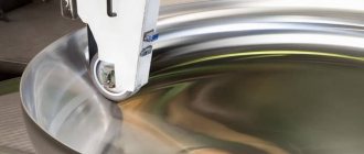
The production of metal objects is a complex technological cycle. Some operations can be either excluded from this chain or repeated. During processing, the metal undergoes changes and flaws may appear on it. Next, you will learn what types of defects there are in metal products, as well as how they can be identified.
Types of defects in metal products
Due to defects, the physical and mechanical properties of metals, such as electrical conductivity, magnetic permeability, strength, density, and ductility, deteriorate. It is customary to identify defects of a fine structure or atomic scale, namely dislocations, vacancies, etc., and more coarse ones. The latter include submicroscopic cracks that appear at the boundaries of crystal blocks and on its surface.
Micro- and macroscopic defects of metal products, suggesting a violation of continuity or homogeneity, are considered even more serious. They appear for two reasons: due to the imperfection of the technology used and the low manufacturability of multicomponent alloys. The fact is that when working with such alloys, it is necessary to especially strictly observe the regimes established for all stages of manufacturing and processing.
From the point of view of applied, technical understanding, defects are deviations from the established norm, in which the performance characteristics of a metal or metal product deteriorate, a reduction in grade or rejection of products occurs. But you need to understand that not every metal flaw applies to the product. If deviations do not affect the performance of the metal part, they are not perceived as defects.
Deviations recognized as defects for products operated under certain conditions (for example, under fatigue loading) may not be taken into account under other operating conditions (for example, under static loading).
Casting defects in metal products
Today in metallurgy it is customary to use several classifications of defects obtained during casting.
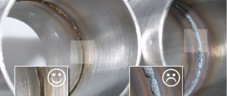
Defects are divided into types based on location. So, if a defect is detected inside a site, it is considered internal. If the problem appears during further processing, it is classified as an external defect.
From the point of view of external manifestations, the following main types of casting defects are distinguished: burn-in, in which a layer of molding materials sintered with the metal is firmly attached to the surface of the workpiece, and tides, which represent an upward deviation of the dimensions of the castings from the design.
Tides are divided into:
- Bays that form along the junction of parts of the form. The reason for their appearance lies in non-compliance with the dimensions of the models and poor connection of the elements of the flasks.
- Puffiness (thrust) - occurs due to the pressure of the melt on the loose mixture.
- A build-up that occurs when the flow of melt erodes a mold during pouring.
- Notches (ridges, burrs) formed when the melt flows into damage to the mold or rod.
Often, defects during casting appear in the form of surface defects. These include:
- Blockages. Masses of earth grains or slag. This problem appears due to errors made when designing molds, ill-conceived placement of gates, and failure to comply with storage and transportation technology.
- Uzhiminy - are formed during wet molding, when the layer of earth is torn at the point of liquid condensation and the melt fills the resulting void.
- Joints, or non-stilines, occur when contact occurs between layers of cooled melt. Since the required temperature is not reached, the threads cannot fuse properly.
- Films - appear when alloying additives oxidize.
- Wrinkling or folding. This defect looks like multidirectional folds on the surface of a metal product. This flaw is associated with the accumulation of a large volume of carbon in the metal.
- Effusion provokes an explosive release of graphite accumulations, so it looks like many burst bubbles.
- Kinglets also appear due to splashing of the melt during pouring. In this case, the metal ball crystallizes separately from the casting, without connecting with it.
- Warping of the casting occurs due to internal stresses provoked by uneven cooling.
Types of damage depending on the influences causing them
Impacts that cause damage are divided into the following groups:
Mechanical (power)
Damage from force impacts occurs in cases where at the design stage the probable external loads and internal forces were incorrectly calculated and, as a result, the cross-sections of the elements were incorrectly selected. Another possible mistake is an illiterate solution to structural components. Characteristic signs of defects in metal structures resulting from such miscalculations are: cracks in the body of elements and welds, weakening of threaded and riveted connections, curvatures, local deflections, abrasive wear and, as a consequence, loss of stability of the metal structure.
Mechanical damage may occur due to changes in comparison with the design: sections of elements, dimensional characteristics of welds, number and/or type of fasteners. The reasons for their appearance are also loads during operation exceeding design values, violation of the relative position of metal structures during installation, sharp and strong impacts. Mechanical damage is caused by: cutting out holes not provided for in the design documentation and removing design connecting elements.
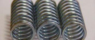
Structures subject to dynamic loads (crane beams, work platform beams) are subject to fatigue damage. They are characterized by the appearance of cracks in the base metal, welds and heat-affected areas, weakening or complete destruction of rivet and threaded connections.
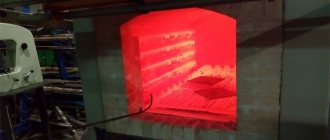
Temperature
High temperature exposure leads to warping of elements and damage to anti-corrosion coatings; negative temperatures lead to the appearance of brittle cracks.
Damage from high temperatures most often occurs in metal structures operated in hot shops. Such structures usually provide movable connections that can move freely when the temperature changes. If such movable connections are absent, then additional stresses of a cyclic nature appear in the structures. They lead to the formation of cracks and bending of individual elements. At temperatures of +100°C, anti-corrosion coatings are destroyed, and at +300…+400°C, warping of elements of small and medium thickness occurs.
Damage caused by freezing temperatures usually occurs in steel structures operated outdoors or in unheated areas. Sudden cooling is especially dangerous. Brittle cracks often appear at low temperatures in metal structures made from boiling steel.
Chemical and electrochemical
As a result of chemical and electrochemical influences, corrosive destruction of steel and damage to anti-corrosion coatings occur. Steel structures used in industrial facilities are characterized by electrochemical corrosion.
Corrosion damage is divided into the following groups:
- General uniform and uneven . They are located over the entire surface of the structure. Reduce the thickness of elements and increase internal stresses.
- They look like ulcers, pittings, and through holes. Significantly increase internal stress concentrations, leading to brittle destruction of metal structures under sudden mechanical stress and subzero temperatures.
The solution to the problem of the appearance and development of damage to metal structures is to strengthen them by increasing the cross-sectional area of the elements, using additional connections or changing the design schemes.
Plastic defects in metal products
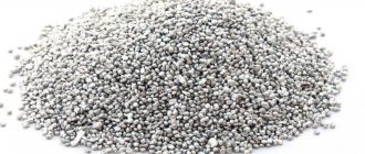
When rejecting workpieces, quite often one has to deal with inclusions of foreign metallic or non-metallic bodies, and the latter come in different sizes and shapes.
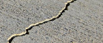
A tear is a local non-through rupture located across or at an angle to the direction of processing of the material. Such defects are formed due to the disclosure of internal discontinuities in the material, as well as non-compliance with the standards established for the processing process.
A through gap differs from the previous type in that through discontinuities are observed on the metal product. They are formed when a flat workpiece with uneven thickness is deformed, or the cause of a through rupture can be rolled-in foreign bodies.
The puncture looks like non-through single or group point depressions. They appear when contaminated cutting fluids are used or small metal and foreign elements come into contact with the workpiece. Another reason for pinching can be protrusions and stuck particles on the rollers.
We recommend articles on metalworking
- Steel grades: classification and interpretation
- Aluminum grades and areas of their application
- Defects in metal products: causes and search methods
Dents are individual single depressions of various sizes, shapes, and having flat edges. Dents appear due to damage to the metal during production, transportation, and storage.
A nick is an irregularly shaped depression. Typically, such a defect has sharp edges, as it appears when a metal product is hit.
Imprint – periodically repeating depressions, protrusions located throughout the metal product or in some of its areas. Imprints appear under the influence of irregularities on the rolling and straightening rolls.
The seizure looks like a wide longitudinal depression with an uneven bottom and edges. The reason for its appearance is the sharp friction of the workpiece against the part of the equipment with which processing is carried out.
A notch is a longitudinal narrow depression, the bottom of which can be rounded or flat. Formed when a metal product blank is scratched by protrusions on the surface of the equipment.
A scratch is an irregularly shaped depression with a random direction. Appears due to mechanical damage, for example, during storage or transportation of metal products.
Abrasion is a loss of shine on a particular area of a metal product, as well as an accumulation of small multidirectional scratches. Such defects appear due to friction between metal products.
Adhesion occurs as a result of particles or a layer of metal from a tool sticking to a metal product.
Sunset is formed due to the pressing into the product of particles of the metal being processed, burrs, protrusions and other defects that appear during the processing process.
Burnout manifests itself in the form of dark, melted or oxidized spots on a metal product, which are formed if the temperature and heating time of the material have been exceeded.
The photo album of metal defects contains more than 200 photographs and schematic images of metal surface defects detected during visual and measurement inspection. In addition to photographs, each defect has a definition from regulatory documentation. The name of each defect is duplicated in English, German and French. At the end of the album there is a list of recommended literature and tools for visual inspection.
The album material is based on the following documents:
- GOST 21014-88 “Rolled ferrous metals. Terms and definitions of surface defects";
- GOST 19200-80 “Castings from cast iron and steel. Terms and definitions of defects";
- RD 03-606-03 “Instructions for visual and measuring control”.
A photo album of metal defects can be used in the training and certification of welders and flaw detectors for visual and measuring control, and is also of interest to scientists in the field of metallurgy. For educational and scientific work, it is also recommended to use the first part of this publication - Photo Album of Welding Defects.
Contents of the photo album of metal defects
Defects according to GOST 19200-80:
1. Defects of non-conformity in casting geometry:
- Underfilling
- Neslytina
- Crimping
- Puffiness
- Skew
- Rod warp
- Difference in thickness
- Rod Bay
- Warping
- Nezaliv
- Breakout
- Overcut
- Metal breakthrough
- Metal care
2. Casting surface defects:
- Burnt
- Spay
- Uzhimina
- Growth
- Bay
- Blockage
- Captivity
- Notching
- Surface damage
- Folding
- Gas roughness
- Rough surface
3. Continuity defects in the casting body:
- Hot crack
- Cold crack
- Intercrystalline crack
- Gas sink
- Sieve shell
- Shrinkage shell
- sand shell
- Slag sink
- Poured slag
- Graphite porosity
- Shrinkage porosity
- Gas porosity
- Looseness
- Boil
- Utyazhina
4. Inclusion defects:
- Metal inclusions
- Non-metallic inclusions
- Korolek
5. Defects of inconsistency in structure:
- Whitewash
- Half-heartedness
- Segregation
- Flocken
Video presentation of the photo album Defects in the base metal
Subscribe to our YouTube
Defects according to GOST 21014-88:
1. Surface defects caused by the quality of the ingot and cast billet:
- Rolled out (unchained) pollution
- Volosovina
- Rolled (uninhibited) bubble
- Bubble-bloating
- Delamination
- Bullion flaw
- Ingot captivity
- Rolled out burnt stick
- Rolled out (unchained) crack
2. Surface defects formed during deformation:
- Deformation flaw
- Flaw on the edges
- Tight edge
- Zakov
- Rolling captivity
- Stress crack
- Birdhouse
- Us
- Undercut
- A cut
- Wrinkles
- Sunset
- Risk
- Through breaks
- Tears
- Prodir
- Punctures and punctures
- Rolled out prints
- Prints
- Scaly
- Rolled scale
- Ryabizna
- Scale sinks
- Rolled metal particles
- Sink-indent
- Lagging scale
- Rolled-in foreign particles
- Splashes
- Gray spots
- Stains of pollution
- Welding spots
- Burr
- Notches
- End crack
- Sliding stripes
- Cold hardening strips
- Kinks
- Tarnish colors
3. Surface defects formed during finishing operations:
- Etching cracks
- Sludge deposit
- Poor grass
- Overtrawl
- Scale residues
- Etching shades
- Rust stains
- Dents
- Scratches
- Grinding cracks
- Matte coating
See also the sections - Welder templates, Visual inspection kits, Samples for visual inspection certification, Certification of VIC specialists, Certification of laboratories using the visual method.
A photo album with various types of surface defects in the base metal can be purchased with delivery to your door or to the terminals of a transport company in the following cities: Moscow, St. Petersburg, Yekaterinburg, Saratov. Amursk, Angarsk, Arkhangelsk, Astrakhan, Barnaul, Belgorod, Biysk, Bryansk, Voronezh, Veliky Novgorod, Vladivostok, Vladikavkaz, Vladimir, Volgograd, Volgodonsk, Vologda, Ivanovo, Izhevsk, Yoshkar-Ola, Kazan, Kaliningrad, Kaluga, Kemerovo, Kirov , Kostroma, Krasnodar, Krasnoyarsk, Kursk, Lipetsk, Magadan, Magnitogorsk, Murmansk, Murom, Naberezhnye Chelny, Nalchik, Novokuznetsk, Naryan-Mar, Novorossiysk, Novosibirsk, Neftekamsk, Nefteyugansk, Novocherkassk, Nizhnekamsk, Norilsk, Nizhny Novgorod, Obninsk, Omsk , Orel, Orenburg, Okha, Penza, Perm, Petrozavodsk, Petropavlovsk-Kamchatsky, Pskov, Rzhev, Rostov, Ryazan, Samara, Saransk, Smolensk, Sochi, Syktyvkar, Taganrog, Tambov, Tver, Tobolsk, Togliatti, Tomsk, Tula, Tyumen , Ulyanovsk, Ufa, Khanty-Mansiysk, Cheboksary, Chelyabinsk, Cherepovets, Elista, Yaroslavl and other cities, also in the Republic of Crimea. As well as the Republic of Kazakhstan, Belarus and other CIS countries.
Methods for detecting defects in metal products
There are several levels of examination that are used for different depths and sizes of defects:
- Submicroscopic examination.
- Microanalysis.
- Macroanalysis.
Defects in the crystalline structure of metals are usually understood as deviations from the structure of an ideal, that is, defect-free, crystal.
Crystal structure defects are divided into types according to their shape and size:
- Dislocations, that is, the absence of a half-plane of the crystal lattice.
- Vacancies or voids in the nodes of the crystal lattice.
- Interstitial atoms, which imply the presence of additional atoms in the lattice between the nodes.
- Substitution atoms, that is, atoms of another element located in the nodes of the crystal lattice of the metal being processed.
1. Submicroscopic examination.
Its purpose is to identify defects at crystal or grain boundaries. The fact is that due to uneven crystallization or insufficient nutrition of the nuclei with a liquid solution, thin layers appear between the blocks of crystals. Or the reason may be hidden in the release of insoluble compounds and elements on the surface of the crystals of the solid phase. Thus, phosphorus and a number of refractory metals are not able to form compounds with iron in steels, so they are deposited at the grain boundaries.
Submicroscopic defects include chips in steel 38Kh2MYuA. The reason for their appearance is simple: during alloying of steel with aluminum, local planes are identified along the grain boundaries, which become the weak point of the metal during further processing.
2. Microanalysis.
In such a study, microscopes with a magnification of more than 100 times are used to identify defects. It is microanalysis that is most often used when searching for casting defects. This method allows you to determine the grain score, the presence and number of inclusions of non-metallic nature, copper, sulfur and phosphorus, and the structure of the metal.
The proportion of carbon and alloying elements contained in the steel determines which solid phases will be released during crystallization. Note that these stages have different strength, hardness and ductility. In corrosion-resistant steel grades, austenite, martensite or ledoburite phases are formed at different cooling temperatures.
Also, the key characteristics that determine the quality of the metal include the grain grade. The fact is that when this indicator decreases, the ductility of the metal increases, but its strength decreases. However, alloying with carbide formers or refractory materials makes it possible to strengthen the steel while maintaining its original ductility.
Inspection of metal structures, types of defects and damage
1. GENERAL PROVISIONS. There are requirements for the inspection of the most common load-bearing structures of industrial buildings and structures using modern and affordable tools and devices.
The scope and program of inspection of metal structures are determined in each specific case by the technical specifications approved by the Customer’s management and depend on the condition of the metal structure elements. The survey materials are the initial data for drawing up a conclusion about the condition of metal structures or developing a project for their restoration, strengthening, or reconstruction. The guidelines should facilitate qualified inspection, identification of defects and damage to metal structures of industrial buildings and structures, and selection of the most effective method of restoration, repair and strengthening of damaged elements of metal structures. When performing work on the inspection of metal structures, it is necessary to comply with the requirements of safety regulations. 2. PREPARATORY WORK.
Before the start of the survey, it is necessary to carry out a preliminary (reconnaissance) inspection of the object to determine the volume, specifics and focus of the survey, the necessary preparatory work (making scaffolding and ladders to provide direct access to structures, cleaning surfaces, etc.), as well as identifying the need for special research (measurement of dynamic characteristics, geodetic survey, etc.).
During the preliminary inspection, first of all, you should pay attention to the structures that cause concern, and, if necessary, limit the loads or completely unload the structures. In the event of an emergency, reliable safety anchorages should be immediately assigned. The inspection of metal structures must be carried out by specialists from organizations that have the appropriate licenses, under agreements with the management of the energy enterprise. Equipment and measuring instruments used in technical diagnostics and determination of material properties, the degree of corrosive wear and deformation of metal structures must have the necessary accuracy and meet the requirements of the standards. All measuring instruments used must have a valid verification (calibration) mark and a verification (calibration) certificate. 3. SELECTION OF TECHNICAL DOCUMENTATION AND FAMILIARIZATION WITH OPERATING CONDITIONS.
When inspecting metal structures, it is necessary to have comprehensive information about the structures of the object being examined, the features of manufacturing, installation, construction and operating conditions of metal structures. For this purpose, before the start of a visual inspection, technical documentation must be selected and analyzed in full.
The technical documentation to be analyzed during the inspection of metal structures should include:
- passport for the building or structure being inspected;
- working drawings at the CM stage, containing diagrams of design loads, calculations and structural diagrams, drawings of components and custom steel specifications for profiles;
- detail drawings of metal structures at the KMD stage, developed on the basis of drawings at the KM stage;
- documents (crane forms, equipment passports, results of coating openings, etc.) characterizing actual loads and their changes during operation;
- factory certificates for supplied steel structures - documents (certificates, etc.) certifying the quality of the materials used - steel, hardware, electrodes, etc.;
- documents of approval with the design organization in case of deviations from the project;
- acts of acceptance of hidden work;
- data from the results of geodetic measurements when checking alignment axes and installing structures;
- logs of work during the installation of structures;
- damage reports and records of defects identified during operation;
- certificates for repair work, as well as for work to strengthen structures;
- data from geodetic surveys carried out during operation, and, if necessary, data on the soil and permissible loads on the soil;
- -results of previous examinations.
From the set of KMD detail drawings, drawings of structures to be examined are selected: installation diagrams of columns, vertical and truss trusses; installation diagrams of trusses and connections along the upper and lower chords of the trusses; installation diagrams of crane beams and brake platforms, etc. From the set of CM working drawings the following must be selected: data on design loads (permanent and temporary) indicating the places of their application, plans, cross-sections and longitudinal sections of the structures being inspected, structural units, necessary calculations. The initial data for assessing the material of the structures being examined can be: the year of steel production and technical conditions for its supply, the results of control mechanical tests and chemical analyzes of specially cut samples, cold bending tests and impact strength.
When studying the operating conditions of the object being inspected, it is necessary to familiarize yourself with the documents and materials defining:
- operating conditions of a building or structure from the beginning of its commissioning;
- service life of a building or structure and repair and restoration work or reconstruction work performed during this time;
- damage to structures that occurred during operation (materials from previously made corrections and strengthening of structures);
- the presence of an aggressive environment and significant temperature effects on structures;
- values and places of application of permanent and temporary loads, as well as their possible operational combinations;
- changes in loads during operation, indicating the dates of their changes.
Information that cannot be determined from documents is revealed through interviews with operating personnel, as well as directly during the inspection of structures.
In the absence of structural drawings, sketches are drawn up based on measurements in kind. 4. INSPECTION OF THE CONDITION OF METAL STRUCTURES.
The inspection of metal structures is carried out after the selection and analysis of technical documentation.
Full-scale inspection of structures is carried out for the purpose of:
- checking the compliance of structures with the design;
- identifying defects and damage resulting from deviations from the requirements of building codes and regulations (SNiP) during the manufacture, installation, transportation, storage and unsatisfactory operation of structures;
- identifying the actual conditions and features of the operation of structures.
Checking the compliance of structures with the project is carried out by comparing the nature with the working drawings of KM and KMD. In this case you need to do:
- full-scale measurements of the main geometric parameters (spans and heights of beams, trusses, column spacing, etc.);
- measuring the cross sections of working structural elements, measured in two or three places along the length of the element on a surface previously cleaned to a shine;
- measuring the location of joints, measuring sections, stiffeners, connecting elements, connections, supporting parts, etc.;
- comparison with the design of butt joint structures, structures of supporting parts that determine the load-bearing capacity (support tables, support plates, anchor bolts, etc.).
In the absence of a design for metal structures of buildings and structures, measurement drawings are drawn up, which should include:
- plan, longitudinal and transverse sections of buildings and structures with breakdown of axes and rows, geodetic marks;
- plan of metal structures of girders, connections along the upper and lower chords of trusses;
- plan, diagrams and sections of columns;
- diagram of vertical and horizontal connections between columns.
The following are subject to visual inspection in order to identify defects and damage: columns, rafter and sub-rafter trusses, purlins, horizontal and vertical connections between trusses and columns, crane tracks, crane beams with their braking structures and other structures.
When examining metal structures, special attention should be paid to:
- columns - the condition of the shoes, anchor bolts of the connecting lattice elements, butt joints of the wall and chords, the presence of mechanical damage, the verticality of the columns, the degree of corrosion of the columns in the support units at the base and at the levels of the coating and ceiling marks;
- rafter and sub-rafter trusses - straightness of the compressed chord and compressed elements (especially those made up of small profiles), the condition of connections and support nodes, nodes with sharp stress concentrators, defects in welds, the condition of anchor bolts and support plates for 16 trusses on reinforced concrete columns and brick pilasters ;
- vertical and horizontal connections - the presence of curvatures and bends (in the plane and out of the plane), the state of attachment to structures, as well as the integrity of the elements of the connections themselves;
- crane tracks (rails and their fastenings) - wear of the rails, the size of the gaps at the joints of the rails, the condition of the rail fastenings, the position of the rail relative to the axis of the crane beams;
- crane beams - the condition of the metal and welded joints of the upper and lower chords of the beams with the walls, the condition of butt joints, stiffeners, supporting parts, as well as the condition of the attachments of beams to columns;
- brake pads - the state of fastening of the brake plate to the crane girder belt and columns, the presence of weakening in the brake plate by cutouts not provided for by the design, the state of fastenings of the brake grid elements and tie elements.
First of all, during an inspection, attention should be paid to defects that lead to a decrease in the load-bearing capacity of structures or to unreliability and imperfection of the overall spatial layout of the building or structure being inspected.
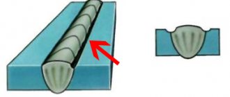
5. INSPECTION OF WELDED JOINTS.
Welds must satisfy a set of requirements for mechanical strength, ductility, impact strength, resistance to the formation and propagation of cracks. The strength of a welded joint depends on the length and height of the seam, the mechanical properties and quality of the seam and base metal. Welded joints must have full penetration, good continuity of the deposited metal, must have high mechanical properties and be equal in strength to the base metal. Quality control of welds must be carried out in accordance with the requirements of SNiP III-18-75 “Metal structures. Rules for production and acceptance of work."
When inspecting welds and base metal in the heat-affected zone, special attention should be paid to:
- places of direct impact of dynamic loads (for example, on the upper waist seams of crane beams);
- ends of fillet welds (for example, in attaching lattice beam and truss elements to gussets);
- places of intersection and change in direction of welds;
- the presence of intermittent seams in welded beams, columns and other load-bearing structures;
- cracks of all types, directions and sizes (signs of the presence of cracks are streaks of rust appearing on the surface of the metal, peeling paint, etc.).
When inspecting welds, first of all, you should pay attention to defects that can lead to brittle cracks (arson of the base metal at the beginning of the weld and along it, poor-quality completion of the weld - the appearance of craters, shrinkage microcracks, etc.), continuity of welds , as well as their sizes (leg and length). When determining the actual length of the weld, which is included in the subsequent verification calculation, gaps and 20 mm at the beginning and end of the weld are subtracted from its total length.
When identifying cracks, special attention should be paid to the following welded joints and assemblies:
- columns and racks - butt joints, joints of structural elements, support units;
- rafter and sub-rafter trusses - support units, joints of chords (especially in stretched zones), welds located across the force acting in stretched elements, zones of convergence of welds on all nodal gussets;
- crane beams - zones of convergence of welds (for example, in the interfaces of stiffeners with chords, at the intersection of stiffeners, etc.), welded joints (especially in stretched zones), attachment points for brake trusses, attachment points for brake sheets and support diaphragms, heat-affected zones at the ends of short stiffeners, support units, rail fastenings.
The most negative impact is exerted by cracks located along the axis of the weld and narrow, deep lack of penetration, since a sharp increase in stress can occur at their sharp edges. When structures operate under dynamic loads, the presence of both cracks and lack of fusion is completely unacceptable. Under static load, any cracks and lack of penetration with a depth of more than 10-15% of the metal thickness are unacceptable. A special place among possible defects in seams is occupied by pockets of corrosion that arise during the operation of structures in chemically active environments.
The degree of influence of defects and damage on the strength of metal structures depends on the shape of the defects, their depth and location in relation to the direction of the acting forces. The most dangerous defects are those that have an elongated shape and sharp outlines. In welded seams of metal structures, only shallow defects can be allowed, not exceeding 5-10% of the thickness of the elements being connected. For elements operating under static loads, the most dangerous is the location of defects perpendicular to the maximum tensile force. It is most carefully necessary to inspect the junctions of ribs, diaphragms, various linings, places with different thicknesses and shapes of seams, seams with technological defects (lack of fusion, undercut edges, sagging, pores, slag inclusions, craters, etc.).
Defects and damage to welded joints are detected using the following methods:
- External defects of welded joints (surface cracks, imperfect seams, undercuts, burns, etc.) - by external inspection. Before inspection, the weld and adjacent metal are cleaned of slag and metal spatter. Inspection is carried out with the naked eye in good lighting (a magnifying glass is used if necessary). Seam measurements are carried out using special templates and measuring tools.
- Internal defects of welds (lack of penetration, porosity, non-metallic inclusions, cracks, etc.) - by drilling the seams and etching the drilling points. In some cases, the quality of seams can be checked using X-rays, ultrasound or magnetography.
Before inspection, metal structures must be cleaned of dirt and dust.
Places where cracks may be present must be free of corrosion and cleaned to a metallic shine. Weld seams must also be cleaned of paint and slag using metal brushes. When cleaning, it is prohibited to hit the seams with a chisel or hammer, which will leave dents and nicks on the deposited and base metal. In doubtful cases, the corresponding area of the metal (weld area) must be cleaned with an emery wheel, file, sandpaper and etched. The presence of a hard-to-see crack is detected by removing thin metal shavings in the direction of the suspected crack. The bifurcation of the chips confirms the presence of a crack in this location. For selective examination of individual seams of questionable quality, microanalysis of the ground and etched section of the seam is used. The quality of individual seams can be determined by drilling holes with an electric drill and etching with a 10-12% aqueous solution of a double salt of copper chloride and ammonium. After etching, the deposited metal darkens, and lack of penetration, slag and other defects become visible. At the end of the work, the holes are brewed. 6. INSPECTION OF RIVETED AND BOLTED CONNECTIONS.
Identification of external defects in rivet and bolted joints is carried out by their external inspection using measuring tools and templates. Loose tightening of bolts, shaking and mobility of rivets, loose filling of holes with the body of the rivet should be established by tapping with a hammer weighing 300 - 400 g with the application of a finger on the opposite side, simultaneously touching the head of the bolt, nut or head of the rivet and the element being connected. Leaks in the connection of elements in the package and leaks in the fit of the heads to the package being riveted are controlled with a 0.2 mm thick probe.
The most dangerous defects of rivet joints that must be eliminated:
- loose pressing of the rivet head to the package being riveted along the entire contour or part of it;
- cracking of the rivet head;
- insufficient or excessive length of the rivet rod;
- mismatch of holes in the riveting elements of the package;
- incorrect centering of rivet heads during riveting;
- rivet corrosion.
The most dangerous defects in bolted connections that need to be eliminated:
- presence of holes not filled with bolts;
- absence of washers under the nuts and, if necessary, locknuts;
- presence of insufficiently tightened bolts;
- displacement of the bolt axes from the design position.
7. DETECTION OF CORROSIVE WEAR AND DAMAGE TO ANTI-CORROSIVE COATING OF METAL STRUCTURES.
The degree of damage to metal by corrosion is determined by establishing the type of corrosion: general (uniform) and local (ulcerative, pitting), crevice, as well as by measuring the size of corrosion damage.
In the case of uniform corrosion, the degree of metal damage is determined by comparing cross-section measurements with the cross-section of the element provided for by the design. In case of local corrosion, the diameter and depth of ulcers or pittings and their number per unit surface are determined. To determine the extent of corrosion damage, elements of metal structures must first be thoroughly cleaned of dirt, old paint and corrosion products to a metallic shine. The thickness of the element weakened by corrosion is measured with a micrometer or caliper at at least three points. If it is impossible to measure the thickness on both sides, ultrasonic thickness gauges (UG-93P, Kravts 15) are used or a hole is drilled through which the measurement is made. The minimum of the measured element thicknesses is taken as the calculated one. Damage to anti-corrosion protective coatings must be determined by visual inspection. Assessment of the condition (size of defects and degree of damage) of anti-corrosion protection should be carried out during the inspection and established in accordance with the requirements of regulatory and technical documents. 8. ASSESSMENT OF METAL QUALITY.
The quality of steel is one of the main factors determining the ability of structural elements to resist destruction, and depends on the grade and manufacturing technology. Metal quality assessment is carried out in accordance with current standards and SNiP, based on certificates, additional tests and analyzes that determine the properties of steel.
Additional mechanical testing, impact testing and chemical analysis to determine the properties of steel in structural members that require repair, reinforcement or replacement are performed in the following cases:
- in the absence of certificates;
- in the absence of data in the certificates regulated by regulatory and technical documents;
- when the design stresses in the elements exceed the design resistance of steel grade StO (in tension, compression and bending 170 MPa);
- when operating conditions, combinations, nature and values of loads change;
- when cracks are detected in structures;
- when using welding;
- when the state of structures and operating conditions raise concerns about the possibility of their brittle destruction.
Determination of steel properties is carried out in order to:
- assessment of the mechanical properties necessary for the calculation;
- determining the possibility of using welding in eliminating defects and strengthening structures;
- assessing the reliability of metal structures during their operation;
- determining the ability of structural elements to withstand brittle fracture.
To determine the properties of steel it is necessary to:
- mechanical tests of samples under static tension (yield strength, tensile strength, relative elongation under tension are determined). The selection of workpieces for mechanical testing is carried out in accordance with GOST 9454-78 “Metals. Test method for impact bending at low, room and elevated temperatures.", production of samples and their testing for static tension in accordance with GOST 1497-84 "Metals. Tensile test methods";
- impact strength test on standard samples 10 or 5 mm wide with a U-shaped notch at operating temperature, if it is below minus 20°C; at a temperature of minus 20°C, if the operating temperature is above minus 20°C; after artificial aging at a temperature of 20°C. The production of samples to determine impact strength and testing at normal and low temperatures are carried out in accordance with GOST 9454-78 “Metals. Test method for impact bending at low, room and elevated temperatures." To determine impact toughness, samples are selected in such a way that one of the faces of the sample coincides with the surface of the metal and, after processing, retains its traces (for control) and so that the axis of the cut is perpendicular to this plane;
- chemical analysis for the content of carbon, silicon, manganese, sulfur and phosphorus.
To evaluate steel by the degree of deoxidation, namely to determine boiling, semi-quiet and calm steels, one should proceed from the percentage of silicon.
According to GOST 380-94 “Ordinary quality carbon steel. Grade" its content in steel grade StZ is:
- in boiling steel - up to 0.07%;
- in semi-mild steel - 0.05-0.17%;
- in mild steel - 0.12-0.30%.
Sampling to determine the chemical composition is carried out in accordance with GOST 7565-81 “Cast iron, steel and alloys. Sampling method for chemical composition", and chemical analysis - according to GOST 22536.1-88 "Carbon steel and unalloyed cast iron. Methods for determining total carbon and graphite." Chips for chemical analysis are selected over the entire thickness of the rolled product and, if possible, evenly across the entire cross-section of the element in an amount of at least 50 g (from one element). If it is impossible to take chips over the entire cross-section of the element, it is allowed to take chips by drilling through the entire thickness of the rolled product in the middle third of the width of the element or profile flange. Before collecting chips, the surface of the element at the sampling site must be cleaned of scale, paint, dirt, rust, oil and moisture (to a metallic shine). Selected workpieces must be stamped with a core or paint; the chips must be packaged and labeled. For selected blanks and chips, a statement is drawn up indicating the element, profile, cutting location, and mark. When analyzing cases of destruction of metal structures, in addition, the distribution of sulfur inclusions is revealed using the Bauman imprint method and the microstructure of the steel is determined. Steel samples for testing are taken from a batch of elements. One batch includes no more than 30 elements of the same standard size (sheet, angle, etc.), the same grade of steel, included in the same type of structures of the same delivery or the same production period. The number and size of blanks cut from elements of one batch depend on the selected types of tests and the number of samples (specimens) for each type of test (see table below).
| Type of test | Number of elements from one batch | Number of samples (samples) | |
| from element | total from a batch of elements | ||
| Tensile test | 2 | 1 | 2 |
| Chemical analysis | 3 | 1 | 3 |
| Impact strength at: +20°C -20°C | 2 2 | >3 >3 | >6 >6 |
| Prints according to Bauman: | 2 | 1 | 2 |
When cutting blanks with an oxygen flame, allowance for machining should be given at least one thickness of rolled stock, but not less than 20 mm.
Sampling sites should be located on the least stressed areas of the elements:
- in the lower chords of the trusses - on free horizontal flanges in the lowermost nodes with hinged design support of the trusses or in the least loaded panels of the chords with a continuous truss design;
- in braces - on free shelves in nodes;
- on gussets with minimally loaded braces;
- on the lower chords of beams - on their supporting areas;
- in the walls of beams - in their middle part;
- in solid section columns - in the middle part of the wall.
All samples for mechanical testing are cut from long and packaged rolled products - along the rolling direction, and from sheet and wide rolled products - across the rolling direction.
Sampling locations should be designated away from areas with stress concentrators, and subsequent reinforcement of these locations should be carried out with the reinforcement elements overlapped to the base metal (butting them end-to-end should be excluded). The quality of steel is assessed based on the results of comprehensive tests, taking into account the relationship between chemical composition and mechanical properties. Resistance to brittle fracture is judged based on a comparison of the results of additional tests with the standards regulated by the current SNiP for a given structure, and, if necessary, also with the data of SNiP, GOST, OST and technical conditions for the supply of steel valid for the period of construction of the structures being examined. Based on chemical analysis data and the requirements of GOST 380-94 “Ordinary quality carbon steel. Grade" the steel grade must be established. 9. DETERMINATION OF ACTUAL LOADS AFFECTING ON METAL STRUCTURES.
To establish the causes of damage to individual elements of metal structures of building frames and structures, in some cases, during an examination it is necessary to identify actual and predicted loads, impacts and operating conditions.
The examination determines:
- loads from the own weight of metal structures (trusses, columns, braces, etc.), which are determined from design data or from field measurements (in the absence of a design);
- loads from stationary technological equipment, accepted in accordance with technical documentation;
- loads from the mass of enclosing structures of walls and coverings resting on the frame;
- snow, wind and dynamic loads on structures, taken according to the instructions [3];
- crane loads taken according to the factory characteristics of the crane given in the passports;
- loads from the mass of people, repair materials, dust deposits.
The examination takes into account:
- uneven foundation settlements;
- temperature effects;
- exposure to an aggressive environment;
- abrasive wear.
In addition, the inspection takes into account the state of anti-corrosion protection and contamination of metal structures, traces of the use of metal structures in functions unusual for them.
10. DEFECTS AND DAMAGES.
The most typical defects and damage to elements or structures in general are:
- deformations of individual elements or structures as a whole in the form of bends, deflections, curvatures, etc.;
- deviation or displacement of structural elements from the design position;
- absence of individual elements in structures;
- non-design placement of structural elements;
- violation of the geometric dimensions of sections or profiles of elements;
- mechanical or temperature damage to metal;
- cracks of various types in metal;
- defects and destruction of butt and joint connections (welded, riveted, bolted);
- presence of stress concentrators in structures;
- mutual displacement at the junctions of structures;
- destruction of anti-corrosion protective coatings and corrosion damage to metal and joints;
- weakening of the cross sections of elements (cutouts, potholes, abrasion, etc.);
- poorly executed reinforcement of structures;
- deformations in structural elements due to uneven settlement;
- non-design application of loads on structural elements during operation (suspension of process equipment, suspensions allowed during repair work, etc.).
Defects and damage during inspection of metal structures are identified using the following methods:
- General and local deformations (deflections, bends, bending, bulging, bending, dents, etc.) of metal structures as a whole or individual elements should be determined by tensioning a thin wire between the ends of the structure or element and measuring the maximum distance between the wire and the structure or element .
- When measuring local deformations (deflections, dents, etc.), it is allowed to use a metal ruler applied to the structural element instead of a wire.
- The deviation of the metal structure as a whole or its individual elements from the vertical should be detected using a plumb line and level, measuring the maximum value of the deviation with a ruler, tape measure, etc. or geodetic survey.
- Deviations of metal structures from the design position in plan must be determined, as a rule, by geodetic survey. It is allowed to determine the displacement of the structure in plan using a wire, ruler, tape measure, etc.
- The width of cracks in metal should be determined using a graduated magnifying glass or a measuring microscope.
Detected deviations from the design, defects and damage must be reflected in special statements and diagrams.
Lists of defects must be compiled for individual types of structure (trusses, columns, beams, etc.) indicating the location of the defect (name of the panel rod, distance to the node, etc.). The statements must contain special diagrams; defects must be described in detail and recorded, indicating the dimensions that characterize them. 11. CONCLUSION.
The general purpose of inspections of the technical condition of building structures is diagnostics, identification of the degree of physical wear, the causes of defects and damage, the actual condition (operability of structures) and the development of measures to ensure normal (safe) operation. The need for survey work, its volume, composition and nature depend on the specific tasks assigned. The inspection can be carried out both for the entire building as a whole, and for individual types of structures: roofing, walls, foundations. Based on this work, conclusions are drawn about the suitability of a given building or structure for further operation, taking into account existing or planned loads. And the conditions under which the building as a whole and its individual structures in particular are suitable for use.