Currently, welding of dissimilar steels is often encountered in various industries. This action is most often necessary in cases where there is a need to create connections from steels that differ in their properties: for example, to connect in one product a part made of high-alloy steel, which will be exposed to aggressive influences during operation, and a part made of low-alloy steel, which the load during operation will be significantly less.
The concept of dissimilar steels and features of their welding
Dissimilar steels are steels that differ in their chemical composition, degree of alloying, classes, types, degree of thermal conductivity and susceptibility to welding to each other.
When welding dissimilar steels, one should take into account a key feature that is inherent in the vast majority of welded joints created: during the welding process, intermetallic structures can form, that is, compounds of two or more metals that have a higher melting point than the original steels that were used to create products. However, such structures can be very fragile, and this can lead to weld failure if welding technology is not followed.
In order for the resulting seam to be as dense and high-quality as possible, the edges of the parts to be welded must be preheated using a gas torch or blowtorch. This will not only allow excess moisture to evaporate at the preparatory stage, but also prepare the part for welding in accordance with its physical and chemical parameters.
Dissimilar metals
Welding a package of metals with different chemical and physical properties causes a number of difficulties associated with differences in electrical conductivity, melting temperatures, the tendency to form brittle structures and differences in plastic properties, etc. All this affects the dimensions of the cast core and its location relative to the parting plane of the sheets , leads to the formation of defects in the cast core and the heat-affected zone.
Using various technological methods that regulate heat removal, using rational modes, it is possible to obtain a connection of the required quality. However, this is not always possible when there is a sharp difference in the physical properties of the materials being welded.
When spot welding, a cast core is formed in a closed volume, so changes in its properties due to interaction with the atmosphere are excluded. According to modern concepts, when welding dissimilar metals, a cast core is formed as a result of intense mixing of the metal by convection currents resulting from the combined action of the magnetic field of the welding current and the compression force. Diffusion of individual elements from the heat-affected zone into the cast core is also possible. All this leads to the formation of a metal of a new chemical composition. Traces of mixing can be detected in the first stage of metal melting. Subsequently, the composition of the core becomes equalized.
When welding metals with different properties, the cast core shifts towards the part with lower electrical thermal conductivity and melting point. Difficulties may increase if a part with increased electrical and thermal conductivity also has a smaller thickness. In such cases, a symmetrical arrangement of the cast core can be achieved by adjusting the heat dissipation using methods used when welding parts of unequal thickness. To increase heat dissipation into a metal part with lower electrical conductivity, electrodes with a large mass, a more developed contact surface and an intensive cooling system, made from electrode alloys with better conductivity, should be installed on its side.
However, good weldability of dissimilar metals is not always possible, especially when there is a sharp difference in physical properties. A typical example of limited weldability of dissimilar metals is spot welding of steel and aluminum. The weldability of these metals, given their mutually limited solubility, depends on the formation of brittle intermetallic phases of iron and aluminum. The destructive force when cutting such samples is significantly lower than when welding base metals to each other. When using galvanized welded sheets, the strength of the connection increases significantly, since alloying molten aluminum with zinc changes the conditions for the formation of brittle phases in the welding zone.
In some cases, it is possible to improve the weldability of dissimilar metals by introducing steel spacers (screens) into contact between the part and the electrodes, which serve as an additional source of heat and at the same time reduce its removal into the electrodes. An example of such connections in the automotive industry would be welding flat springs made of 65G steel to low-carbon steel instead of riveting (Fig. 10). In modes of medium hardness, it is possible to obtain quite satisfactory connections using a spacer (a waste from cutting a hole) between the electrode and the spring. On the other hand, the role of this gasket is played by the part. The use of double-sided heat shields in this case reduces the cooling rate and reduces the degree of hardening of the spring.
Rice. 10. Spot welding of spring steel with a heat shield: 1 - remaining gasket (heat shield); 2 - flat spring; 3 - main part
Even with the use of heat shields, the highest hardness in the heat-affected zone reaches HRC 60 with a hardened spring hardness of HRC 42-46. In the cast core, the hardness is reduced to HRC 50-54 due to the reduction in carbon content as a result of mixing with low-carbon steel. In a cast core, small defects in the form of shrinkage holes or even small cracks are possible that do not reduce quality. Fatigue tests under alternating loads on these connections gave good results. This was also facilitated by the design features of such a connection. During operation, the weakened area of the spring (the heat-affected zone, which has increased hardness) is unloaded by the heat shield pad, and the maximum bending moment is transferred to its end.
Satisfactory quality joints were obtained when spot welding ductile cast iron with steel, despite the large difference in melting temperatures and electrical resistivity. Spot welding of a package of two sheets of different thicknesses: steel-cast iron [thickness (0.3-1) + 5 mm] provides the best results when using malleable cast iron, annealed to ferrite. The worst results are obtained when welding ordinary gray cast iron, in which graphite is present in plate form. In such a connection, the weak point is the transition zone, which has a brittle ledeburite structure. Ductile iron annealed to ferrite produces a significant amount of ferrite, which imparts toughness and crack resistance to the transition zone. Welding is performed under relatively harsh conditions. For better heat removal from the cast iron side, an electrode with a large contact surface is used.
Types of dissimilar steels based on structural heterogeneity
Based on the carbon content of steels, they are divided into the following types:
- carbon steels . They are the most common, as they are created on the basis of an alloy of iron and carbon. Depending on the amount of carbon in the alloy, they are divided into low-carbon, medium-carbon, heat-resistant, cold-resistant;
- alloy steels . Depending on the chemical elements included in the steel, low-alloy and high-alloy steels are distinguished.
Depending on the presence of sulfur and phosphorus in the chemical composition of steels, they are divided into:
- red-brittle steels (the chemical composition of which contains sulfur);
- cold-brittle steels (the chemical composition of such steels contains phosphorus);
- heat- and cold-resistant steels (from which impurities of sulfur and phosphorus have been removed by deoxidation, or chemical elements have been introduced that neutralize their effect).
Welding methods and technologies depending on the dissimilarity of steels
The choice of welding method for certain dissimilar steels depends, first of all, on their physicochemical properties. Currently, the most common types of joints of dissimilar steels are:
- low-carbon steels, low-alloy steels, tool steels and steels of unknown composition . To assess the weldability of dissimilar steels, attention should be paid to the carbon equivalent Ce. When steels with different Ce are welded, the welding parameters are selected for steel with a larger Ce, and the filler material is selected for steel with a smaller Ce. With correctly selected modes and filler material, the hardness and mechanical properties of the deposited metal will be in the range between the steels being welded. Otherwise, there is a high probability of cracks forming. The choice of preheating temperature before welding also depends on the carbon equivalent and is selected for steel with a large Ce. When welding steels with a significant difference in Ce values, it is recommended to perform a stress relief tempering. Controlled cooling of the parts being welded or reducing their cooling rate reduces the risk of cracks;
- stainless steels with low carbon steels . Welding such steels leads to the simultaneous formation of hard and brittle structures in the weld seam, which can be caused by a violation of welding technologies. At the same time, when welding stainless steel with low-carbon or low-alloy steel, the welds are of high quality, provided that all technological requirements for the process are carefully observed. However, it should be noted that the variety of combinations of these steels does not allow us to formulate general recommendations for their welding, which would guarantee a good result in all cases. For welding high-alloy and low-alloy steels, high-alloy or nickel-based filler material is usually used. You can also pre-fuse a transition layer of stainless steel onto a low-carbon or low-alloy steel edge before welding. Then welding is carried out with an additive similar to stainless metal;
- cast iron with steel . Cast iron has limited weldability; this is the main criterion for the selection of welding materials and welding parameters. If there are no special requirements for the weld, then welding is carried out using nickel-based filler materials. It is undesirable to use welding processes associated with high heat input or the formation of a large weld pool. White cast iron and some other high carbon cast irons are not weldable due to their tendency to crack. In some cases, it is advisable to deposit a transition layer with a nickel-based filler material onto cast iron edges. Small parts are subjected to general heating before welding, large workpieces are heated around the welding zone. An important fact is that cast iron has low lamellarity and a low coefficient of linear expansion. To solve this problem, it is necessary to reduce shrinkage stresses. The best way to achieve this is to hammer the weld immediately after welding with an impact tool with a rounded head. It is also recommended to use electrodes of a smaller diameter during welding. To deposit a transition layer on a cast iron edge, manual arc welding and flux-cored arc welding are used. For welding with a steel edge, manual arc welding and welding with consumable electrode wire of a solid section or metal cored wire in inert or active shielding gases are used;
- low alloy steels with low carbon steels . The limited migration of alloying elements when welding low-alloy steel does not generally result in increased hardening susceptibility of the weld metal for all basic welding processes. Welding materials are selected for low-carbon steel, and welding modes are selected for low-alloy steel. Recommended welding methods: manual arc welding, submerged arc welding, consumable solid electrode wire or metal cored wire in inert or active shielding gases;
- different low carbon steels with each other . If both welded edges belong to the same type of alloying, but at the same time have different equivalents of carbon Ce, then the welding is carried out using welding materials of an identical type of alloying. For welding steels with a high tendency to harden, it is recommended to use manual arc welding. To avoid the formation of cold cracks in the heat-affected zone, it is desirable to reduce the specific heat input during welding and avoid slow welding speeds. High-strength steels, which have a very high tendency to harden, require preheating to sufficiently high temperatures, as well as post-weld treatment. An alternative is to use special austenitic filler materials with minimal preheating. Recommended welding methods: manual arc welding, flux-cored arc welding, submerged arc welding, welding with a non-consumable tungsten electrode in an inert shielding gas, welding with a consumable electrode wire of a solid section or metal-cored wire in an inert or active shielding gas;
- tool, spring steels with carbon and low-alloy steels . Due to the polymorphic phase transformations that occur during heating and cooling, these steels are difficult to weld. Welding such steels requires the use of special techniques. When welding products of small thickness, welding can be carried out without preheating. In other cases, heating to a temperature of about 300 degrees is required, which must be maintained during the entire welding process. Minimal heat input into the weld pool is required. Recommended welding methods: manual arc welding with coated electrodes, arc welding with flux-cored wire, welding with a non-consumable tungsten electrode in an inert shielding gas, welding with a consumable electrode wire of a solid section or metal-cored wire in an inert or active shielding gas;
- high alloy stainless steels with tool and spring steels . The main requirement when welding such steels is the use of welding consumables that produce an austenitic stainless steel or nickel-based alloy. Recommended welding methods: manual electric arc with coated electrodes, arc welding with flux-cored wire, welding with a non-consumable tungsten electrode in an inert shielding gas, welding with a consumable electrode wire of a solid section or metal-cored wire in an inert or active shielding gas;
- dissimilar high-alloy stainless steels to each other . When welding such steels, the weld seams are of high quality. However, when carbide-stabilized high-alloy stainless steels are welded to unstabilized stainless steels, carbide-stabilized welding consumables or low-carbon welding consumables should be used. It is also necessary to limit the heat input into the weld pool. Recommended welding methods: manual arc welding, flux-cored arc welding, welding with a non-consumable tungsten electrode in an inert shielding gas, welding with a consumable electrode wire of a solid section or metal-cored wire in an inert or active shielding gas;
- steel of unknown or questionable composition with other steels . When repairing steel structures, it is not always possible to analyze the chemical composition of steels. When performing welding work with steels of unknown chemical composition, you should select welding materials and modes as for difficult-to-weld steels. The preferred welding method is manual arc welding with a coated electrode. High quality of welded joints when welding dissimilar steels is ensured by compliance with welding technology, welding materials used, welding methods and modes. Even minor deviations from the requirements for welding such joints lead to the formation of defects and cracks.
Features of welding dissimilar steels
5.1 When developing welding technology, it is necessary to take into account the technological features of the steels being welded, the difference in their properties, the possibility of the formation of defects specific to each of the steels being welded, the development of structural inhomogeneities (transition zones, crystallization and diffusion layers), which can affect the performance of welded joints.
5.2 The most significant influence on the technological and operational characteristics of dissimilar welded joints is exerted by crystallization (martensitic) and diffusion (carbide) layers formed during the welding and operation of dissimilar welded joints, including non-austenitic steels welded with austenitic welding materials.
5.3 Features of welding of such dissimilar joints are determined:
— the need to use welding materials that provide austenitic weld metal;
— formation and development of chemical and structural inhomogeneities in the welded joint zone, including crystallization and diffusion layers along the fusion line of the austenitic weld with non-austenitic steel;
— dependence of the chemical composition, structure of the weld metal and properties of welded joints on the degree of penetration of non-austenitic steel;
- difference in linear expansion coefficients of welded steels.
5.4 The possibilities of ensuring the austenitic structure of the weld metal and the minimum thickness of the crystallization layer depend on the chemical composition of the weld metal, which is determined by the chemical composition of the welding wire and the degree of penetration of the base metal.
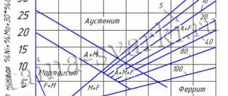
Welding materials that provide an austenitic structure to the weld metal of a dissimilar joint according to the Scheffler diagram (see Figure 5.1), respectively, provide the permissible thickness of the crystallization layer. Thus, the use of welding materials containing at least 12-13% nickel and limiting the share of the base metal (no more than 30%) in the weld metal correspond to the specified conditions.
5.5 When designing welded structures, it is not recommended to select dissimilar butt welded joints without preparing the edges. If it is necessary to use such connections, welding materials containing 25% nickel or more should be used, depending on the thickness of the metal being welded.
5.6 Welded joints made with austenitic welding consumables with a high nickel content are prone to hot cracking. Therefore, in this case, it is necessary to take measures to prevent hot cracks:
— use of welding materials containing molybdenum;
— use of moderate welding modes;
— ensuring the optimal shape of the seam, etc.
5.7 The main measures to prevent the formation of diffusion layers are:
— use in structures of non-austenitic steels with a sufficient content of carbide-forming elements;
- refusal of heat treatment of the welded product or reduction of the tempering temperature and holding time;
— the use of welding materials with a high content of nickel and other alloying elements that inhibit the diffusion of carbon;
— use of moderate welding modes that reduce overheating of welded joints;
— intermediate cooling of welded joints after surfacing each bead in multilayer welding;
— preliminary cladding of non-austenitic steel with high-nickel steel, followed by welding of the edges with sparingly alloyed welding material;
— reduction in the degree of penetration of the base metal (non-austenitic steel).
5.8 When welding dissimilar welded joints, including steels of the non-austenitic class, welded with austenitic welding materials, the necessary limitation of the formation and growth of diffusion layers is ensured by compliance with the requirements of tables 8.1 - 8.3 , regarding the use of welding materials, and by limiting the share of non-austenitic steel in the weld metal, which is not must exceed 30%.
5.9 Welded joints made of dissimilar steels, which differ significantly in thermophysical properties, are characterized by the fact that it is impossible to reduce the internal welding stresses in them. In such joints, instead of welding stresses after heat treatment, new “tempering” stresses arise, which have a more unfavorable distribution than in the as-welded state.
Therefore, when designing such structures and technologies for their manufacture, it is advisable to abandon heat treatment and provide welding materials, surfacing of edges or inserts that provide a gradual (step-by-step) change in thermophysical properties.
Figure 5.1 - Scheffler diagram
5.10 Heat treatment of dissimilar welded joints, including non-austenitic materials and performed with austenitic welding materials, is not allowed. In exceptional cases, heat treatment is carried out as specified in the technical design.
Heat treatment of dissimilar welded joints made with non-austenitic welding materials is carried out according to the regimes of more alloyed steels.
5.11 In welded joints of steels having different coefficients of linear expansion and operating at temperatures above 400°C, thermal stresses arise, which can have a negative effect on the strength of the joint. In this regard, for critical welded assemblies operating under cyclic loading conditions, special calculations are required. The performance of welded joints in steels of different structural classes must be assessed taking into account the total effect of operating, residual and temperature stresses, as well as cyclic loads.
Requirements for making welded joints
6.1 Welded structures must be designed taking into account the rational use of combinations of dissimilar steels and the implementation of the maximum amount of welding work at the manufacturer.
6.2 When designing critical (loaded) structures made of dissimilar steels of different structural classes, it is recommended:
— prefer butt joints to other types: corner, T-joint, overlap. The location of the seams should ensure the convenience of welding and the reliability of its implementation;
— locate heterogeneous connections in the least loaded areas of the structure and in areas of low operating temperatures;
— exclude stress concentrators in the area of dissimilar seams as much as possible;
— provide effective control for the absence of external and internal unacceptable defects;
— make constructive and other decisions that eliminate the need for heat treatment;
- exclude heat treatment of dissimilar welded joints, including heat-resistant or high-chromium stainless steels, as well as carbon and low-alloy steels with a thickness of over 30 mm, made with austenitic welding materials;
— for elevated temperatures and difficult operating conditions, introduce intermediate structural elements made of more stable steels or surfacing into the connection in order to limit the development of brittle layers.
6.3 When developing a technological process for welding dissimilar steels, it is necessary to take into account:
— technological features (weldability) of steels and alloys, special requirements (heating, heat treatment, etc.) that are accepted for dissimilar joints in accordance with the current regulatory and technical documentation for welding both steels constituting a dissimilar joint;
— the possibility of the formation of defects, especially cold and hot cracks, specific to each of the steel being welded;
— the possibility of the formation and development of structural inhomogeneities (diffusion and crystallization layers);
— the necessity and sufficiency of ensuring the mechanical properties and corrosion resistance of welded joints.
6.4 The maximum operating temperature of dissimilar welded joints of austenitic steels with carbon and low-alloy manganese-silicon steels of the pearlitic class should not be higher than the lower one allowed for both steels, but not higher than 470°C.
The maximum minimum temperature should not be lower than the highest allowed for each steel, but not lower than minus 40°C. Dissimilar welded joints made with welding materials containing 60% nickel can be operated at temperatures not lower than minus 60°C.
Note - Dissimilar welded joints made with welding materials containing 40% nickel can be used down to minus 60°C, provided that the degree of penetration of pearlitic steel is no more than 20%.
6.5 The maximum operating temperature of dissimilar welded joints of steels of the austenitic class with chromium-molybdenum steels of the pearlitic and martensitic classes should not be higher than the lower one allowed for both steels, but not higher than 600°C. The maximum minimum temperature must not be lower than 0°C.
6.6 When welding steels of the same structural class of different grades, it is allowed to use one of the welding materials recommended for welding any of these grades.
6.7 When welding dissimilar joints of carbon (S-01) and low-alloy (S-02, S-03) steels (pearlitic class) with low-alloy pearlitic steels (S-02, S-03, S-04) and medium-alloy martensitic class (C -05), preference should be given to more technologically advanced welding materials, which, as a rule, are less alloyed, providing a lower tensile strength and higher ductility and toughness of the weld metal. In some cases, for specific operating conditions, the use of austenitic welding materials is allowed, the technology of use of which must be agreed upon with a specialized organization.
6.8 When welding dissimilar joints of high-alloy corrosion-resistant steels of the austenitic and austenitic-ferritic class (S-07, S-08, S-09), alloys (S-10) with pearlitic steels (S-01, S-02, S-03, C-04), martensitic (C-05), ferritic, martensitic-ferritic and martensitic (C-06) classes, preference should be given to less alloyed welding materials that provide an austenitic structure of the weld metal with a ferrite content of at least 2%. The upper limit of the permissible ferrite content depends on the operating temperature of the welded joint and should not exceed the values specified in Table 6.1.
Table 6.1 - Permissible content of ferrite phase in austenitic weld metal
| Operating temperature of welded joints, °C | Permissible content of ferrite phase, score according to GOST 11878 |
| Up to plus 350 | Not limited |
| In the range plus 350 - 450 | |
| In the range plus 450 - 550 | |
| In the range plus 550 - 700 | |
| In the range plus 700 - 900 |
The nickel content in welding materials depends on the operating temperature of dissimilar welded joints and must comply with the requirements of tables 8.1 - 8.3 .
6.9 Heat-resistant steels of pearlitic and martensitic classes (S-04-1, S-04-2, S-05), as well as high-chromium steels of ferritic, martensitic-ferritic and martensitic classes (C-06), when welding them with other structural steels classes require heating, according to tables 8.1-8.3. The exception is pearlitic class steels of type 12ХМ (S-04-1), ferritic and martensitic-ferritic classes with a thickness of no more than 10 mm. It is allowed to weld heat-resistant steels of pearlitic and martensitic classes (S-04-1, S-04-2, S-05) and high-chromium steels of ferritic, martensitic-ferritic and martensitic classes (C-06), regardless of the thickness of the dissimilar joint, without heating when using welding materials containing at least 40% nickel.
6.10 The heating temperature is controlled by contact or non-contact infrared thermometers, thermal pencils, thermal paints, digital contact and laser non-contact thermocouples.
Temperature measurements are made within the uniform heating zone at a distance of at least two product wall thicknesses in each direction from the weld axis.
6.11 Welding of dissimilar joints of steels of austenitic and austenitic-ferritic classes (S-07, S-08) with alloys (S-10-1, S-10-2) is recommended to be carried out with welding materials used for welding alloys on an iron-nickel base, and welding alloys of group C-10-1 with alloys of group C-10-2 - welding materials used for welding nickel-based alloys, giving preference to welding materials used for welding the specific alloy being welded.
6.12 When using austenitic welding materials for welding dissimilar welded joints, including heat-resistant steels (S-04, S-05), as well as steels of ferritic, martensitic-ferritic and martensitic classes (C-06), subject to heat treatment according to the requirements of the project, it is recommended to use welding materials containing at least 40% nickel (ANZHR-1, ANZHR-2, Sv-08Х20Н60М10, Sv-08Х25Н40М7, etc.).
6.13 For welding dissimilar joints, including heat-resistant steels and operating in environments that cause corrosion cracking, it is allowed to use austenitic welding materials containing at least 40% nickel.
6.14 The need for heat treatment of dissimilar compounds is determined taking into account the requirements of section 4.4 PB 03-576 , section 11 of STO 00220368-008 and this STO.
Dissimilar welded joints are subject to heat treatment, including:
— steels of groups C-01, C-02, C-03 with a thickness of over 30 mm, welded using the pearlite method;
— steels of groups S-04, S-05, except pearlitic steels of type 12ХМ (S-04-1) with a thickness of up to 10 mm, welded on pearlitic material;
— steels of groups S-07, S-08 or alloys of groups S-10-1, S-10-2 if there is a requirement for resistance to MCC.
The need for heat treatment of welded joints of dissimilar steels should be established at the design stage of welded assemblies of apparatus and pipelines.
6.14 When welding with austenitic welding materials containing 12-14% nickel, dissimilar joints of steels of groups C-01, C-02, C-03, C-04, C-05 and C-06 with other groups of materials, it is necessary to take measures to limiting the proportion of non-austenitic steel (≤ 30%) in order to limit martensite in the weld metal and prevent cold cracks, which can be achieved:
— the use of RDS and argon-arc welding with a non-consumable electrode, semi-automatic welding in argon and argon-based gas mixtures (Ar + 20% CO2, Ar + 5% O2, etc.), automatic submerged arc welding with direct current of direct polarity;
— using technological methods, such as preliminary surfacing of edges, limiting welding modes, etc.
Note - The degree of penetration is controlled experimentally when selecting a welding mode, during the manufacture of welded products, by the hardness of the weld metal or metallographically.
6.15 When welding non-austenitic steels with austenitic welding materials, the root part of the weld, without subsequent removal of metal from the reverse side, is recommended to be performed with welding materials containing at least 40% nickel.
6.16 When welding dissimilar joints using welding materials containing 40% nickel or more, it is necessary to take measures to prevent the formation of hot cracks (welding should be performed with narrow beads of limited compact cross-section, without transverse vibrations of the electrode, at the highest possible speed, for automatic submerged arc welding, use AN-18 flux, use preliminary surfacing of edges, carefully weld craters, etc.).
6.17 Welding of heat-resistant steels of groups C-04-1, C-04-2 and C-05 is performed with pearlitic welding materials used for less alloyed steel with subsequent heat treatment of dissimilar welded joints. Welding with austenitic welding materials without heat treatment is allowed.
6.18 Welding of martensitic steels with austenitic welding materials is permitted when the content of emulsified water in petroleum products is not more than 0.2%, chloride salts are not more than 10 mg/l and caustic soda is not more than 30 g/t of oil product.
6.19 The use of connections with austenitic welds is not allowed:
— in zones of separation of moisture from petroleum products (clause 18.78 RD 38.13.004 );
— for welding longitudinal joints of pipe elements and shells.
For welding pipe elements of catalytic reforming plants operating using the oxychlorination process, welding materials containing at least 40% nickel must be used.
6.20 When welding dissimilar joints, including steels of pearlitic (S-01, S-02, S-03, S-04-1, S-04-2), martensitic (S-05) classes with a thickness of more than 12 mm, with austenitic welding materials It is recommended to perform preliminary surfacing of the edges of these steels in order to:
— saving expensive high-nickel welding materials;
— reducing the chemical and thermophysical heterogeneity of compounds;
— increasing the technological strength (resistance to cold and hot cracks) of dissimilar welded joints.
Note:
1. Surfacing of edges with welding materials containing up to 25% nickel is carried out with heating at 150-200°C.
2. Heat treatment of welded joints is not required.
6.21 When welding dissimilar heat-resistant steels of pearlitic and martensitic classes (groups S-04-1, S-04-2, S-05), it is allowed to use preliminary welding of the weld root with electrodes of the E42A type, followed by filling the groove with austenitic welding materials. Such connections can be used in environments that cause corrosion cracking at temperatures up to 260°C.
6.22 When welding dissimilar joints of heat-resistant steels (S-04-1) with carbon steels (S-01), it is allowed to line the edges of the welded parts made of heat-resistant steels with electrodes of the E42A or E46A type, followed by filling the groove with the same welding materials.
Notes
1. Surfacing of edges is carried out with heating at 200-250°C.
2. Heat treatment of welded joints is not required.
6.23 Surfacing of edges is carried out in at least two layers. The thickness of the surfacing after machining should be 5 ± 1 mm for manual arc, argon-arc or semi-automatic welding in argon and argon-based gas mixtures (Ar + 20% CO2, Ar + 5% O2, etc.) and 6 ± 1 mm for automatic submerged arc welding or semi-automatic carbon dioxide welding. The welded edges after machining must comply with the requirements of the standards, see clause 10.1 .
6.24 When welding pipes and pipe parts, special inserts (adapters) can be used, see Figure 6.1. The use of these inserts must be provided for in the design documentation.
a - joints of pipes with different wall thicknesses; b - location of the joint of pipes of dissimilar steels (R.S.) near the rigid fastening; c — insert made of steel of intermediate composition
Figure 6.1 — Inserts in pipelines made of dissimilar steels
The length of the insert L is determined by the permissible distance between the welds in accordance with the requirements of PB 03-576 and PB 03-585 .
6.25 Welding modes, preliminary and accompanying heating, as well as heat treatment should be used taking into account the weldability of less technologically advanced steel included in this connection, given in OST 26.260.3, OST 26.260.480, STO 00220368-008, RTM 26-44. The weldability characteristics of various groups of steels and technological requirements for them are given in Table 6.2.
Table 6.2 - Weldability characteristics of various groups of steels and technological requirements for them
| Material group | Structural class | Brands of domestic materials | Weldability characteristics | Technological requirements |
| S-01, S-02 | Pearlitic | St.3kp, St.3ps, St.3sp, St.3Gps, 10, 15, 20 15K, 16K, 18K, 20K, 22K, 20L, 25L, 16GS, 17GS, 17G1S, 09G2S, 10G2, 10G2S1, 10HSND, 15HSND , 09G2BT, 09G2FB, 20YuCh, 20KA, 09GSNBTS, 09G2SYUCH | Well weldable | — |
| S-03 | Pearlitic | 15G2SF, 10G2FB, 16G2AF, 09ХG2NABCH | Satisfactorily weldable | Limitation of heat input |
| S-04-1 | Pearlitic | 12МХ, 12ХМ, 15ХМ, 12Х1МФ, 15Х1МФ | Prone to cold cracking | Heating 200-300°C for thicknesses over 10 mm, heat treatment |
| S-04-2 | Pearlitic | 10Х2М1, 10Х2М1А-А, 12Х2МФА, 15Х2МФА | Prone to cold cracking | Heating 250-300°C for thicknesses over 10 mm, heat treatment immediately after welding |
| S-05 | Martensitic | 15Х5М, 15Х5MU, 15Х5ВФ | Prone to cold cracking | Heating 350-400°C for thicknesses over 10 mm, heat treatment immediately after welding |
| S-06 | Ferritic, martensitic-ferritic | 08X13, 12X17, 08Х17Т, 15Х25Т, 12X13, 14Х17Н2 | Prone to embrittlement (ferrite grain growth) and cold cracking | Heating 150-200°C for thicknesses over 10 mm, heat treatment, limitation of heat input |
| Martensitic | 20X13 | Prone to cold cracking | Heating 150-200°C for thicknesses over 10 mm, heat treatment | |
| S-07 | Austenitic | 08Х18Н10Т, 12Х18Н10Т, 12Х18Н9Т, 12Х18Н9ТЛ, 08Х18Н12Б, 12Х18Н12Т, 03Х18Н11, 02Х18Н11, 08Х18Н10, 04X18Н10 | Prone to hot cracking | Limitation of heat input |
| Austenitic-ferritic | 08Х18Г8Н2Т, 12Х21Н5Т, 15Х18Н12С4ТУ, 06Х22Н6Т | Prone to hot cracking and embrittlement (ferrite grain growth) | Limitation of heat input | |
| S-08 | Austenitic, austenitic-ferritic | 08Х17Н13М2Т, 10Х17Н13М2Т, 10Х17Н13М3Т, 12Х18Н12М3ТЛ, 03Х17Н14М3, 08Х17Н15М3Т, 08Х21Н6М2Т | Prone to hot cracking | Limitation of heat input |
| S-09 | Austenitic-ferritic, austenitic | 20Х23Н13, 08Х20Н14С2, 20Х20Н14С2, 20Х23Н18, 10Х23Н18, 20Х25Н20С2, 12Х25Н16Г7АР | ||
| S-10-1 | Iron-nickel alloys | 03ХН28МДТ, ХН30МДБ, 06ХН28МДТ, ХН32Т, ХН35ВТ, ХН35ВТУ, ХН38ВТ, 03Х21Н21М4ГБ | Prone to hot cracking | Limitation of heat input, alloying of weld metal with molybdenum |
| S-10-2 | Nickel-based alloys | KhN63MB, KhN65MV, KhN65MVU, N70MFV-VI, N65-VI, KhN75MBTYu, KhN78T | Prone to embrittlement due to grain growth and formation of intermetallic compounds | Limitation of heat input |
6.26 Welding of parts and assemblies is permitted only after the quality of the assembly has been accepted by the quality control department.
welding equipment
7.1 To perform welding work, any type of equipment can be used that provides the welding modes and operational reliability specified by this STO.
7.2 For automatic welding, welding machines such as ADF-1250, ADF-800, ADF-1000, TS-17S and others, commercially produced by industry, are used.
7.3 For semi-automatic welding, welding machines of the type PDG-351, PDG-525, PDGO-510 and others, commercially produced by industry, are used. It is recommended to use inverter-type devices SINERMIG-401 and others.
7.4 Welding rectifiers such as RD 306 S1, RD-309, RD-413, as well as multi-station rectifiers such as VDM-2×313, VDM-6301, VDM-6303S, VDM-1202S, VDM- are used as a power source for RDS and argon-arc welding 1201, VDM-1601 and others. It is recommended to use inverter-type devices Raduga-180, Raduga-250 and FALTIG-400 and others.
7.5 For semi-automatic welding in shielding gases, welding rectifiers such as VS-300B, VDG-303, VDG-410, VS-600S and others are used.
7.6 For RDS and semi-automatic welding in shielding gases, it is recommended to use universal welding rectifiers such as VDU-506, VDU-511, VDU-601 and others.
7.7 For automatic welding and surfacing under submerged arc and in shielding gases, it is recommended to use universal welding rectifiers such as VDU-630, VDU-800, VDU-1250, VDU-1202, VDU-1601 and others.
7.8 Fluctuations in the voltage of the supply network to which the welding equipment is connected are allowed no more than ±5% of the rated value.
7.9 To reduce deformations of welded parts, it is recommended to use jigs and other special technological devices.
Welding materials
8.1 For welding parts and assemblies made of dissimilar steels and alloys, the recommended welding materials are given in tables 8.1 - 8.3.
Steel grade 08X13 (C-06) and welded joints of this steel are used for unloaded structures.
When welding dissimilar joints of one structural class with welding materials of another structural class, any welding materials used for dissimilar joints of different structural classes, including a material of this structural class, can be used. For example, for welding St.3 steel with 12ХМ steel, in addition to welding materials intended for welding carbon and low-alloy steels, austenitic welding materials can be used.
8.2 As a non-consumable electrode for argon arc welding, use lanthanum tungsten rods in accordance with GOST 23949 with a diameter of 2-4 mm.
8.3 Tungsten electrodes must be sharpened to a cone at an angle of 15°. Before each pass, you should inspect the sharpening and if damage or contamination of the end of the tungsten electrode is detected, replace it or restore the sharpening.
8.4 When argon arc welding, the highest grade argon is used as a protective medium in accordance with GOST 10157 .
Table 8.1 - Electrodes for manual arc welding
| Combination of welded steels of different groups in a welded joint (A + B) | Electrodes | Permissible operating temperature, welding conditions | |||
| A | B | Standard | Type | Brand | |
| S-01 (Art. 3) | S-02 (16GS), S-03 (15G2SF) | GOST 9467 | E-42 E-42A E-46 E-46A | ANO-5 UONI 13/45 ANO-3 UONII-13/55K | E-42, E-46 not lower than minus 15°C; E-42A not lower than minus 30°C; E-46A not lower than minus 40°С |
| S-04-1 (12ХМ) | Heating to 200-250°C, heat treatment | ||||
| S-04-2 (10Х2М1) | Heating to 200-250°C, heat treatment immediately after welding* | ||||
| S-05 (15Х5М) | Heating to 350-400°C, heat treatment immediately after welding* | ||||
| S-02 (16GS), S-03 (15G2SF) | S-04-1 (12ХМ) | GOST 9467 | E-50A | UONI 13/55 and the like | Heating to 200-250°C, heat treatment |
| S-04-2 (10Х2М1) | Heating to 200-250°C, heat treatment immediately after welding* | ||||
| S-05 (15Х5М) | Heating to 350-400°C, heat treatment immediately after welding* | ||||
| S-01 (St.3), S-02 (16GS), S-03 (15G2SF) | S-06 (08X13) | GOST 10052 | E-10Х25Н13Г2 | OZL-6 and the like | Heating up to 150-200°C, operating temperature from minus 40 to 400°C |
| S-07(08Х18Н10Т), С-08 (10Х17Н13М3Т), С-09 (20Х23Н18), С-10-1 (ХН28МДТ), С-10-2 (ХН78Т) | E-10Х25Н13Г2 | OZL-6 and the like | From minus 40 to 400°C | ||
| E-11Х15Н25М6AG2 | EA-395/9 | From minus 40 to 450°C | |||
| TU 14-168-23 | 10Х25Н25М3Г2 | ANZHR-3U | |||
| TU 14-4-598 | 08Х24Н40М7Г2 | ANZHR-2 | From minus 40 to 460°С | ||
| TU 14-4-568 | 08Х24Н60М10Г2 | ANZHR-1 | From minus 60 to 470°C | ||
| S-04-1 (12ХМ) S-04-2 (10Х2М1) | S-05 (15Х5М) | GOST 9467 | E-09MH E-09X1M | OZS-11 TML-1U | Heating to 350-400°C, heat treatment immediately after welding* |
| S-04-1 (12ХМ), С-04-2(10Х2М1) С-05(15Х5М) | S-06 (08X13) | GOST 10052 | E-10Х25Н13Г2 | OZL-6 | Heating 200-300°C, operating temperature from 0 to 450°C |
| E-11Х15Н25М6AG2 | EA-395/9 | Heating 200-300°C, operating temperature from 0 to 500°C | |||
| TU 14-168-23 | 10Х25Н25М3Г2 | ANZHR-3U | |||
| S-07 (08Х18Н10Т), С-08 (10Х17Н13М3Т) S-09 (20Х23Н18), С-10-1 (ХН28МДТ), С-10-2 (ХН78Т) | GOST 10052 | E-10Х25Н13Г2 E-11Х15Н25М6AG2 | OZL-6 EA-395/9 | Heating 200-300°C, operating temperature from 0 to 525°C | |
| TU 14-168-23 | 10Х25Н25М3Г2 | ANZHR-3U | |||
| TU 14-4-598 | 08Х24Н40М7Г2 | ANZHR-2 | From 0 to 550°C | ||
| TU 14-4-568 | 08Х24Н60М10Г2 | ANZHR-1 | From 0 to 600°C | ||
| S-06 (08X13) | S-07 (08Х18Н10Т), С-08 (10Х17Н13М3Т) S-09 (20Х23Н18), С-10-1 (ХН28МДТ), С-10-2 (ХН78Т) | GOST 10052 | E-10Х25Н13Г2 E-10Х25Н13Г2Б | OZL-6 TsL-9 | Heating to 150-200°C. If there are requirements for MCC up to 350°C (only E-10Х25Н13Г2Б) |
| S-07 (08Х18Н10Т), С-08 (10Х17Н13М3Т), С-09 (20Х23Н18) | S-07(08Х18Н10Т), С-08(10Х17Н13М3Т) S-09(20Х23Н18) | GOST 10052 | E-07Х20Н9 E-10Х25Ш3Г2 | OZL-8 OZL-6 | No requirements for ICC |
| E-04Х20Н9 | OZL-14A | The same, up to 550°C | |||
| E-08Х20Н9Г2Б E-08Х19Н10Г2Б E-09Х19Н10Г2М2Б | TsL-11 TsT-15 NZh-13 | If there are requirements for MCC up to 350°C, higher - after stabilizing annealing | |||
| S-10-1 (KhN28MDT), S-10-2 (KhN78T) | GOST 10052 | E-11Х15Н25М6AG2 | EA-395/9 | From minus 60 to 350°С, subject to requirements for MCC | |
| TU 14-168-23 | 10Х25Н25М3Г2 | ANZHR-3U | |||
| TU 14-4-715 | E-04Х23Н27М3Д3Г2Б | OZL-17U | |||
| S-10-1 (ХН28МДГ) | S-10-2 (ХН78Т) | GOST 10052 | E-10Х20Н70Г2Б2В | OZL-25B | |
| Note: 1. For ease of use, the table shows representatives of brands of each group of materials. 2. Temperature conditions for the use of welded joints are additionally limited by the conditions of use of the materials being welded. 3. In the absence of requirements for MCC, the conditions for using welded joints are determined by the conditions for using the materials being welded. 4. When welding more alloyed nickel- and iron-nickel-based alloys with less alloyed alloys and steels, it is recommended to use electrodes designed for welding more alloyed alloys, see table. 6.1 STO 00220368-008-2006. *After “thermal rest” (350-400°C, exposure 3 hours), the time before heat treatment is not limited. |
Table 8.2 - Welding consumables for automatic submerged arc welding
| Combination of welded steels of different groups in a welded joint (A + B) | Welding wire | Flux | Permissible operating temperature, welding conditions | ||
| A | B | Standard | Brand | Brand | |
| S-01 (Art. 3) | S-02 (16GS), S-03 (15G2SF) | GOST 2246 | Sv-08 Sv-08A Sv-08GA Sv-10GA | AN-348A OSC-45 FC-16 | Sv-08, Sv-08A not lower than minus 20°C; Sv-08GA, Sv-10GA not lower than minus 40°С |
| S-04-1 (12ХМ) | Heating to 200-250°C, heat treatment | ||||
| S-04-2 (10Х2М1) | Heating to 200-250°C, heat treatment immediately after welding* | ||||
| S-05 (15Х5М) | Heating to 350-400°C, heat treatment immediately after welding* | ||||
| S-02 (16GS), S-03 (15G2SF) | S-04-1 (12ХМ) | GOST 2246 | Sv-08GA Sv-10GA Sv-08GSMT Sv-10NYU Sv-10NMA | AN-348A OSC-45 AN-22 AN-47 AN-43 FC-16 | Heating to 200-250°C, heat treatment |
| S-04-2 (10Х2М1) | Heating to 200-250°C, heat treatment immediately after welding* | ||||
| S-05 (15Х5М) | Heating to 350-400°C, heat treatment immediately after welding* | ||||
| S-01 (St.3), S-02 (16GS), S-03 (15G2SF) | S-06 (08X13) | GOST 2246 | Sv-07Х25Н12Г2Т Sv-07Х25Н13 | AN-26S AN-18 48-OF-6 | Heating up to 150-200°C, operating temperature from minus 40 to 400°C |
| S-07 (08Х18Н10Т), С-08 (10Х17Н13М3Т) S-09 (20Х23Н18), С-10-1 (ХН28МДТ), С-10-2 (ХН78Т) | Sv-07Х25Н12Г2Т Sv-07Х25Н13 | AN-26S AN-18 | From minus 40 to 400°C | ||
| Sv-10X16N25AM6 | AN-26S, AN-18 | From minus 40 to 450°C | |||
| TU 14-1-4968 | Sv-08Х25Н25М3 | AN-26S, AN-18 | |||
| Sv-08Х25Н40М7 | AN-18 | From minus 40 to 460°С | |||
| SV-08Х25Н60М10 | AN-18 | From minus 60 to 470°C | |||
| S-04-1 (12ХМ) S-04-2 (10Х2М1) | S-05 (15Х5М) | GOST 2246 | Sv-08ХМ Sv-04Х2МА | AN-348A AN-22, AN-43 | Heating to 350-400°C, heat treatment immediately after welding* |
| S-04-1 (12ХМ), S-04-2 (10Х2М1) S-05 (15Х5М) | S-06 (08X13) | GOST 2246 | Sv-07Х25Н12Г2Т Sv-07Х25Н13 | AN-26S AN-18 48-OF-6 | Heating up to 200-300°C, operating temperature from 0 to 450°C |
| Sv-10X16N25AM6 | AN-26S, AN-18 | Heating up to 200-300°C, operating temperature from 0 to 500°C | |||
| TU 14-1-4968 | Sv-08Х25Н25М3 | ||||
| S-07 (08X18Н10Т), S-08 (10Х17Н13М3Т) S-09 (20Х23Н18), S-10-1 (ХН28МДТ), С-10-2 (ХН78Т) | GOST 2246 TU 14-1-4968 | Sv-10Х16Н25AM6 Sv-08Х25Н25М3 | AN-26S, AN-18 | Heating up to 200-300°C, operating temperature from 0 to 525°C | |
| TU 14-1-4968 | Sv-08Х25Н40М7 | AN-18 | From 0 to 550°C | ||
| TU 14-1-4968 | Sv-08Х25Н60М10 | AN-18 | From 0 to 600°C | ||
| S-06 (08X13) | S-07 (08Х18Н10Т), С-08 (10Х17Н13М3Т) S-09 (20Х23Н18), С-10-1 (ХН28МДТ), С-10-2 (ХН78Т) | GOST 2246 | Sv-07Х25Н12Г2Т Sv-07Х25Н13 Sv-08Х25Н13БТУ | AN-26S AN-18 48-OF-6 | Heating to 150-200°C. When the requirement for MKK is up to 350°C (only brand Sv-08Х25Н13БТУ) |
| S-07 (08Х18Н10Т), С-08 (10Х17Н13М3Т), С-09 (20Х23Н18) | S-07 (08Х18Н10Т), С-08 (10Х17Н13М3Т) S-09 (20Х23Н18) | GOST 2246 | Sv-06Х19Н9Т | AN-26S | No requirements for ICC |
| Sv-04Х19Н9 | AN-26S, AN-18 | The same, up to 550°C | |||
| Sv-07Х18Н9TYU Sv-05Х20Н9ФБС | AN-26S, AN-18 | If there are requirements for MCC up to 350°C, higher - after stabilizing annealing | |||
| S-10-1 (KhN28MDT), S-10-2 (KhN78T) | GOST 2246 | Sv-10X16N25AM6 | AN-26S, AN-18 | ||
| TU 14-1-4968 | Sv-08Х25Н25М3 | AN-26S, AN-18 | From minus 60 to 350°С, subject to requirements for MCC | ||
| GOST 2246 | Sv-01Х23Н28М3Д3Т | AN-18 | |||
| S-10-1 (ХН28МДТ) | S-10-2 (ХН78Т) | TU 14-1-997 | Sv-KhN75MBTYu, Sv-KhN78T | ANF-1, TU 14-1-1948 | |
| Note: 1. For ease of use, the table shows representatives of brands of each group of materials. 2. Temperature conditions for the use of welded joints are additionally limited by the conditions of use of the materials being welded. 3. In the absence of requirements for MCC, the conditions for using welded joints are determined by the conditions for using the materials being welded. 4. Welding flux is supplied in accordance with GOST R 52222. 5. When welding more alloyed alloys with less alloyed alloys and steels, it is recommended to use welding materials intended for welding more alloyed alloys, see table. 6.2 STO 00220368-008-2006. *After “thermal rest” (350-400°C, exposure 3 hours), the time before heat treatment is not limited. |
Table 8.3 - Welding materials for gas-shielded welding
| Combination of welded steels of different groups in a welded joint (A + B) | Welding wire | Protective environment | Permissible operating temperature, welding conditions | ||
| A | B | Standard | Brand | ||
| S-01 (Art. 3) | S-02 (16GS), S-03 (15G2SF) | GOST 2246 | Sv-08G2S Sv-08GSMT Sv-08GS | CO2, Ar | Not lower than minus 40°С |
| S-04-1 (12ХМ) | Heating to 200-250°C, heat treatment | ||||
| S-04-2 (10Х2М1) | Heating to 200-250°C, heat treatment immediately after welding* | ||||
| S-05 (15Х5М) | Heating to 350-400°C, heat treatment immediately after welding* | ||||
| S-02 (16GS), S-03 (15G2SF) | S-04-1 (12ХМ) | GOST 2246 | Sv-08G2S Sv-08GSMT Sv-08GS | CO2, Ar | Heating to 200-250°C, heat treatment |
| S-04-2 (10Х2М1) | Heating to 200-250°C, heat treatment immediately after welding* | ||||
| S-05 (15Х5М) | Heating to 350-400°C, heat treatment immediately after welding* | ||||
| S-01 (St.3), S-02 (16GS), S-03 (15G2SF) | S-06 (08X13) | GOST 2246 | Sv-07Х25Н12Г2Т Sv-07Х25Н13 | CO2, Ar | Heating up to 150-200°C, operating temperature from minus 40 to 400°C |
| S-07 (08Х18Н10Т), С-08 (10Х17Н13М3Т) S-09 (20Х23Н18), С-10-1 (ХН28МДТ), С-10-2 (ХН78Т) | Sv-07Х25Н12Г2Т Sv-07Х25Н13 | CO2, Ar + 20% CO2, Ar + 5% O2 | From minus 40 to 400°C | ||
| SV-10X16N25AM6 | CO2, Ar ⇐ Previous3Next ⇒ Organization of surface water flow: The largest amount of moisture on the globe evaporates from the surface of the seas and oceans (88‰)… Individual and group automatic drinking bowls: for animals. Schemes and designs... Mobile electrified feed dispenser: diagram and process of operation of the device...
| ||||
| © cyberpedia.su 2017-2020 — Not the author of the materials. The exclusive right is reserved by the author of the text. If you do not want this material to appear on our site, please follow the link: Copyright Infringement. We will help you write your work! |
Welding equipment
Regardless of which dissimilar steels being welded we are talking about, equipment for welding work is divided into two groups:
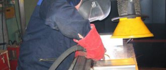
- Working equipment, which includes : welding current source, power supply cables from the electrical network or generators; cables for supplying welding current to the products being welded and creating a welding circuit, in the case of using shielding gas technologies - gas cylinders or special generator devices, welding hammers, metal brushes, power tools (grinders and angle grinders) for final processing of welded joints . In addition, filler materials (welding wire, electrodes), as well as mechanisms for directing them into the welding zone (wire feeding machines, electric holders for electrodes) should be considered as welding equipment.
- Protective equipment . This type of equipment is most often individual and includes: protective clothing impregnated for fire protection, a welding mask with dark glass or a self-darkening mask, leggings or gloves, and safety shoes.
As additional equipment for the welding station, a welding table is considered, as well as tools for securing the parts to be welded in the required spatial positions.