Mechanical tests of welded joints are destructive testing methods that are used to check seams under various loads. With their help, important operational parameters of structures are determined, and then, based on the information obtained, possible loads are calculated. When carrying out inspections, specialized control equipment is used.
Serial samples of welds are selected as control samples. The conclusion is made on the basis of the same studies of fracture resistance and weld ductility.
The essence of mechanical testing of welded joints
Research is carried out in several ways, namely:
- Static . Implies a gradual increase in load. The studies are extended over time so that the destructive load is constant.
- Dynamic . The point is instant impact over a short period of time.
- Fatigue . This is repeated exposure to the sample. The number of cycles is determined by a value that runs into tens of millions. The load is changed according to its value and sign.
Static methods are tests of butt welds that determine their physical characteristics: creep, hardness, ductility, elongation, etc. When testing welds, they are compared with similar samples made of solid metal. In this case, samples with both a cleaned and an uncleaned roller are used.
The conditional yield strength is the stress at which the samples increase by 0.2% of the original length. Flexural tests are carried out to reveal the plasticity of the diffuse layer. The bending load is carried out until the first crack appears on the transverse and longitudinal joint. Tubular or flat samples are used for testing.
Dynamic tests reveal the tendency of seams to fatigue deformation and bending strength. Tests are carried out at reduced, normal or elevated temperatures. The obtained data are recorded in the form of graphs in the protocol.
Hardness is determined in the heat-affected zone and diffuse layer. At the same time, the structural strength of the metal is assessed using metallography methods. Among other things, the untreated and treated suture bead is checked.
Advantages and Disadvantages of Mechanical Testing
The advantages of the methods include the following:
- obtaining data on the performance characteristics of welded joints;
- study of the mechanical properties of seams;
- establishing design values, which allows you to determine maximum loads - information necessary for design work;
- checking the capabilities of the thermally affected zone, the diffuse layer, in which internal defects are often found;
- low costs, but at the same time obtaining accurate results, on the basis of which you can determine the strength characteristics of structures and choose the best method of welding different alloys.
Testing welded joints using mechanical methods also has disadvantages. For example, this is the destruction of samples that cannot be restored. Therefore, these methods cannot be used to accept ready-made compounds - they are used only for research that is carried out at the stage of launching into mass production.
Verification methods
Quality control of welding work performed in production can be destructive or non-destructive. The first methods are used selectively. One or more products from a large batch, or part of a metal product in a building structure, is checked.
It is tested on various parameters using a specific test report. But mainly they use special devices or materials to check the quality of welded joints without destroying the structure.
The main methods of non-destructive welding quality control are:
- visual;
- capillary;
- permeability test;
- radiation;
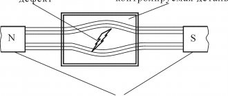
- magnetic;
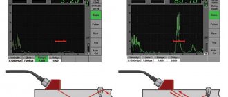
- ultrasonic.
There are other methods and types of welding quality control, but due to their specificity they have not become widespread.
Checking the condition of welds is not a one-time act, it is the resulting stage that shows how the quality control system at the enterprise works.
To minimize defects in welding joints, operational control of the work is carried out. Certification is carried out regularly, at which the commission first gives permission to weld the control joint. When welders pass this test, their theoretical knowledge is tested.
Before starting work, the welder’s qualifications are checked; he must have a certificate for the right to weld certain grades of steel and a work permit.
A welding engineer and a controller from the technical control service check the quality of assembly, the condition of the edges, the performance of the welding machine, and controls the heating temperature, if this is provided for in the regulatory and technical documentation.
Quality control of welding materials is carried out from the moment they arrive at the enterprise and before use at the welding station. The electrodes are checked at each stage of storage and use, and if necessary, they are calcined.
During the actual work, check what welding mode is used: arc welding, argon arc or another type of welding. Check the order of sutures, the dimensions of the layers and the entire connection.
If special requirements are provided for in the design and technical documentation, then their implementation. Upon completion of welding, checks for the presence of the welder’s mark.
Properties that determine mechanical tests
Various methods are used to test seams to determine the mechanical characteristics of the diffuse layer. The samples are subjected to multidirectional forces and it is determined under what load deformation occurs along the seams. In this case, tears, cracks, changes in size and shape are taken into account. Technologically important characteristics that affect the tightness and load-bearing capacity of connections are also determined.
Let us consider the main characteristics that allow us to determine the testing of welded joints.
Plastic
To determine plasticity, static tensile tests are carried out, during which the compliance of the thermally affected area and the diffuse layer and changes in shape are revealed. Plasticity is a characteristic on which the ability of stretch stamping depends. Elongation is determined by measuring samples before and after stretching.
Strength
Strength indicators are especially important for supporting structures that experience multidirectional loads. The reliability, safety, and integrity of a structure depend on strength. Characteristics are determined by several methods. For this purpose, bending and fatigue tests are carried out. Bending tests of welded joints imply applying forces until the moment of critical deformation of the samples. Fatigue tests are carried out with different loads until the sample fails.
During the experiments the following may be carried out:
- Curvature of the workpiece at a given angle.
- Double bend until the sides of the workpiece are flattened.
- Curving thin workpieces until the sides are parallel and the sample takes a U-shape.
Impact bend
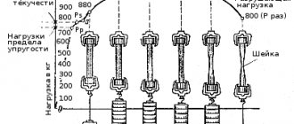
Dynamic studies are performed to determine impact bending. They imply a high rate of load change. Welds are checked for brittleness, susceptibility to cracking and deformation. To do this, use a sample with an incised suture bead. In the place where the cut is made, the stress is concentrated from the impact of a pendulum pile driver with a special scale. As a result of the tests, impact strength is calculated, which is defined as the ratio of the work of repulsion at the point of concentration to the cross-sectional area of the entire sample, i.e. until the cut is made. If cracks, breaks, tears and delaminations do not appear in the sample, then it has passed the test.
Hardness
Three methods are used to determine the hardness of a workpiece:
- Rockwell testing. During the examination, a hard tip is pressed into the metal - an indenter, which is a diamond cone or a steel ball that has undergone special hardening.
- Vickers studies. A method similar to the Rockwell method. A diamond pyramid is used as an indenter.
- Brinell's method. A steel ball with high density and hardness is used.
The hardness of the joint is checked along the longitudinal axis, as well as from the center of the joint towards the base metal of the workpiece.
The Rockwell method is used to control joints on sheet steel or thin metal, the Vickers method on thin parts and thin surface layers, and the Brinell method on other types of workpieces. Hardness directly determines the plasticity of the material, i.e. The harder the diffuse layer, the less it will bend.
3.2. Shape and dimensions of samples for static tension and bending
3.2.1. Cutting a welded control joint with a base metal thickness of less than 50 mm and making samples to determine the characteristics of mechanical properties is carried out according to the drawing diagram. 5.
3.2.2. The static tensile test of the welded joint is carried out on at least two samples of type XII or XIII, GOST 6996-66, which are presented in Fig. 6 and . For a welded joint made of base metal with a thickness of more than 20 mm, if the power of the testing machines is insufficient, it is allowed to produce samples of type XV, GOST 6996-66. The dimensions of flat samples for static tension are given in Table. 1.
It is allowed to test static tension of a welded joint on round cylindrical samples of type II, III, GOST 6996-66.
3.2.3. The static bending test of the welded joint is carried out on at least two samples of type XXVII, GOST 6996-66 (Fig. 8). The thickness of the samples is equal to:
thickness of the base metal for metal up to 20 mm thick;
20 mm for metal thicker than 20 mm.
The static bending test is carried out according to the diagram shown in Figure 9.
3.2.4. The requirements for the manufacture of flat samples for static tensile testing (see Figure 6) are as follows:
the allowance for the width of the sample is removed evenly on both sides;
the reinforcement of the seam is removed to the level of the base metal;
the base metal is allowed to be cut to a depth of no more than 1 mm on each side;
DIAGRAM FOR CUTTING CONTROL PLATES FOR WELDED JOINTS WITH BASE METAL THICKNESS LESS THAN 50 mm
*The length of the weld test plate depends on the thickness of the metal being welded, the welding method, the type and number of samples cut simultaneously, the cutting method and the remainder of the plate for repeated testing.
Crap. 5
FLAT SAMPLE FOR STATIC TENSILE TEST.
Crap. 6
FLAT SAMPLE FOR STATIC TENSILE TEST.
Note. It is allowed to make a sample of type XV without a head
Damn.7
TABLE 1
DIMENSIONS OF FLAT SAMPLES FOR STATIC TENSION
mm
| Base metal thickness | Width of the working part of the sample | Specimen grip width | Length of the working part of the sample | Total sample length |
| Up to 6 incl. | 15±0,5 | 25 | 50 | 200 |
| From 6 to 10 | 20±0,5 | 30 | 60 | 210 |
| » 10 » 20 | 25±0,5 | 35 | 100 | 250 |
| More than 20 | 10±0,5 | 20 | 100 | 280 |
SAMPLE FOR STATIC BENDING OF WELDED JOINT WITH BASE METAL THICKNESS UP TO 60 mm.
TYPE X X VII
Damn. 8
TEST SCHEME FOR STATIC BENDING OF WELDED JOINT
K=2.5D - distance between supports (for sample type XXVII);
D - diameter of the mandrel, mm (taken depending on the steel grade, metal thickness, heat treatment method and must be specified in the regulatory and technical documentation for the product being controlled. In the absence of special instructions, D = 2a);
r=25 mm - radius of curvature of supports
Damn.9
when testing a welded joint made of metal of different thicknesses, a thicker sheet must be brought to the thickness of a thinner sheet by mechanical processing on metal-cutting machines;
difference between the largest and smallest dimensions b over a length l
:
±0.05 mm - at a = 10 mm;
±0.10 mm - at a from 10 mm to 15 mm;
±0.15 mm - at a from 15 mm to 20 mm;
±0.20 mm - when a is more than 20 mm;
The thickening should be removed across the seam. Transverse risks are not allowed;
rounding of edges on the faces of the sample should be removed by lightly smoothing along the sample with a radius of no more than 1 mm;
The marking is applied on the non-working part of the sample.
3.2.5. The requirements for the production of samples for static bending (see drawing) are as follows:
sample width b is 1.5×a, but not less than 10 mm;
the allowance for the width of the sample is removed evenly on both sides;
the reinforcement of the seam is removed to the level of the base metal;
when testing a welded joint made of metal of different thicknesses, a thicker sheet must be brought to the thickness of a thinner sheet by mechanical processing on metal-cutting machines;
the base metal is allowed to be cut to a depth of no more than 1 mm on each side;
at length L/3, round the edges with a radius of 0.2a, but not more than 3 mm;
The seam should be cleaned along the sample. Transverse risks are not allowed;
when testing welded joints with a one-sided seam, the surface layers of the seam should be located in the tensile zone of the sample;
when testing a welded joint with a double-sided seam, the surface layers of the seam should be located in the tensile zone of the sample;
Marking is applied only on the side of the last pass of the seam outside the design part (L/3) of the sample.
Features of mechanical research
The main feature is that mechanical studies are destructive control methods. Those. in most cases, the samples under study are destroyed or damaged. But if destruction is not the best option in a particular case, other testing methods must be chosen.
The room where experiments are carried out must be maintained at the same temperature. The data obtained during the inspection must be recorded.
To obtain the most accurate results, several samples from the same batch are tested. It is likely that results will vary. Then the average value is derived from the obtained indicators - this will be the most accurate result.
It is advisable to use mechanical tests in the serial production of parts, when from each circulation they take the number of products regulated by standards and conduct research. It will not be possible to issue a correct conclusion using only one sample. If the product is single, it is worth using non-destructive testing methods.
Test results depend on various factors. This includes both the original state of the workpiece and the presence of defects in the metal. Therefore, before determining technical characteristics, it is necessary to carry out flaw detection of welded joints, for example, ultrasonic testing.
GENERAL PROVISIONS
1. Quality control of the welded joint as a whole and its individual sections, as well as the deposited metal, by mechanical testing methods is carried out in accordance with the current regulatory and technical documentation and the “Rules for the design and safe operation of pressure vessels”, approved by the State Mining and Technical Supervision of the USSR, ST SEV 798 -77, ST SEV 799-77, ST SEV 800-77.
1.2. Quality control of the welded joint, as well as the deposited metal, by mechanical testing methods or hardness measurements is carried out to the extent specified in the regulatory and technical documentation for the product under control.
1.3. Mechanical tests are carried out to determine the quality of the product and welding materials, the weldability of metals and alloys, the suitability of welding methods and modes when establishing the qualifications of welders. The specific purpose of the tests is indicated in the technical specifications for the controlled product.