Calculation method
There are different options for bonding metal. Calculation of welded joints for each of them is performed separately. Depending on the spatial arrangement of the parts being welded, the welded joints also differ. Accordingly they can be:
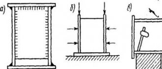
- corner. The connected workpieces are positioned perpendicular to one another. In order for the structure to be as strong as possible, it is necessary to determine the maximum forces that will act on the seams;
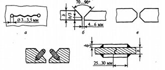
- butt. The workpieces are arranged in one plane in such a way that one of them is a continuation of the other. The ends of the parts are welded. This connection option is considered to be optimal, since it is characterized by minimal levels of tension at the junction. The seam can be oblique or straight;
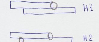
- overlap The planes of the joined workpieces overlap one another. This technology is best suited for connecting parts whose wall thickness does not exceed 5 mm. The method is also used in situations where it is necessary to strengthen the weld;
- T-weld seam. The appearance is very similar to the corner ones. The parts are also located at an angle of 90 degrees in relation to one another, but are connected at their ends. These types of joints are quite in demand and are often used. Among the main advantages of the method are ease of implementation, reliability and cost-effectiveness. In addition, using specially developed guidelines, it is easy to perform calculations for T-joints with impeccable accuracy.
So, it’s time to consider in detail the methodology for calculating the weld. Experts have developed special formulas that simplify the necessary calculations. In addition, there are special programs on the Internet. They are freely available. The user only needs to enter the required parameters to get an accurate result.
Connection calculation method
There are several types of metal bonds and for each of them the calculation of the weld is carried out individually. Depending on the location of the parts being welded, connections are divided into:
- angular , when the parts to be welded are located perpendicular to one another. To increase the strength of the structure, it is necessary to correctly determine the maximum forces on the fillet weld;
- butt. Here the ends of the parts are connected, with one part acting as a continuation of the second. This method of coupling is accompanied by minimal stress concentrations and is considered the most rational. Seams can be straight or oblique;
- overlap , in which the elements of the parts slightly overlap one another. As a rule, this technology is used when welding metals whose thickness does not exceed 5 mm, when it is necessary to strengthen the seam;
- T- bars Externally they resemble corner ones. The fastened elements are located at right angles to each other, but are connected at the ends. In the production of metal structures, such joints are used quite often. They are characterized by ease of execution, cost-effectiveness and high strength. For high-quality execution of this type of connection, a manual will be a good assistant; the calculation of a T-weld joint can be performed using it with impeccable accuracy, and possible errors can be avoided.
How is the cross-section of a fillet weld or other types of joints calculated? There are generally accepted formulas that are used to calculate welds at different joints. There is also a special program for calculating welded joints that is freely available on the Internet, using which, by entering the necessary parameters, you can obtain the required result.
Initial parameters for calculations
In order to eliminate errors during calculations or at least minimize them, you need to decide on the parameters that will affect the strength of the joint. The process of compression and tension of metal is calculated using the formula
Where:
- Yc is a coefficient reflecting the conditions that prevail in the workplace. This indicator is generally accepted and is reflected in reference tables. It is enough to find the desired indicator and substitute it into the formula;
- Rу is an index indicating the resistance of a metal, taking into account its yield strength. Reflected in the welder's reference materials;
- Ru is another indicator of metal resistance that is easy to find in tables;
- N – maximum permissible load on the weld;
- T – the smallest wall thickness of the workpieces being welded;
- Maximum length of weld joint. When calculating, this parameter should be reduced by 2t;
- Rwу – resistance depending on the tensile strength of the connection.
When different metals have to be welded, the values of Ru and Ry are taken from the material whose strength is lower. the same is done in cases where calculations of the welding seam are performed for shear.
The design of metal structures is carried out taking into account the safety requirements of the welded joint, its ability to withstand a certain level of stability loads of the elements connected with them. In cases where several welded joints are required to create a metal structure, it is important to position them correctly. It is important that the welding load is distributed evenly between all joints.
The parameters can be determined by mathematical calculations. If the result obtained is unsatisfactory, changes should be made to the design and calculated again.
What parameters are required for calculation
In order to carry out welding calculations with a minimum error, you should know what parameters affect the strength of the joints. To determine the process of compression and tension of a material, the formula should be used:
When calculating, the following indicators will be required:
- Yc is the coefficient of conditions prevailing in the workplace. the parameter is generally accepted, indicated in standardized tables. It simply needs to be inserted into the formula used to calculate the fillet weld;
- Rу is the resistance of the material being welded, taking into account the yield strength. Determined using standard tables;
- Ru is the metal resistance according to the temporary resistance. The values for the substitution in the formula must be looked for in the tables;
- N is the maximum permissible load that the seam can withstand;
- t is the minimum thickness of the material of the elements being welded;
- lw is the longest length of the welded joint; when calculating, it is reduced by 2t;
- Rwу is the resistance determined depending on the tensile strength.
In the case when it is necessary to weld metals of different structures into a single structure, the Ru and Ry indicators are taken based on the material with the lowest strength.
Also, if you need to calculate a weld for shear, then the indicators should be chosen for the material with less strength.
When designing steel structures, the main requirement is to ensure the maximum possible strength of the joint and the immobility of the elements connected by it. According to the requirements and taking into account the location and size of the seams, it is possible to accurately determine their optimal type. If to create a metal structure it is necessary to make several seams at once, then they must be positioned in such a way that the load is evenly distributed on each of them.
Such parameters can be determined through mathematical calculations. If the results obtained are unsatisfactory, then changes must be made to the design and all calculations must be carried out again with new parameters.
Calculation of products with corner joints
Determination of the permissible tear length of a welded joint is carried out taking into account the force directed towards the center of gravity. When making calculations of this kind, a section with a high degree of danger is selected. Indicators are calculated using the formula:
Each of the formula indicators affects the strength characteristics of the weld, regardless of the type of metal being welded. Legend:
- N is the maximum value of the force that exerts pressure on the joint;
- ßf, ßz – coefficients that are taken in reference tables and do not depend on the type of metals being welded. For the most part, ßz = 1, and ßf = 0.7;
- Rwf is an indicator reflecting shear resistance. Defined by reference materials. The easiest way to find it is in the GOST tables;
- Rwz – resistance along the joint line. The values are taken from the lookup table;
- Ywf is a coefficient depending on the resistance of the material. For example, if for metal this figure is 4200 kgf/cm², then the correction factor will be 0.85;
- C is another coefficient indicating the working environment conditions. Like most values, it is determined from lookup tables;
- Kf – thickness of the weld along the fusion line;
- Lw – total length of the joint, reduced by 10 mm.
Calculation of overlapped joints
When making calculations, it is important to take into account the spatial position and type of welded joint. After all, when overlapping welding, the joints can be corner, flank, or frontal. Calculations make it possible to obtain data on the minimum permissible cross-sectional area and the design strength of the contact line. When calculating the area of a welded joint, the smallest height of a conditional triangular joint is taken as the basis. For manual welding, provided that the legs are equal, this coefficient will be 0.7.
If welding work is performed by automatic or semi-automatic machines, the depth of heating of the material will be greater. Therefore, indicators should be taken in reference tables.
Length of the weld depending on the mass of the metal
The length of the welded joint is determined by the formula that determines the ratio of the weld mass per meter of joint: L = G/F × Y, where
- L – length of the seam itself;
- G – weight of the float;
- F – cross-sectional area;
- Y is the specific gravity of the filler material.
As a result of the calculations, a coefficient will be obtained that should be multiplied by the length of the weld leg.
To perform calculations correctly, you need to practice. It is important to understand that no formula can provide an exact result. Therefore, it is advisable to purchase consumables with a small reserve. This is approximately 5-7% of the total. True, sometimes it turns out to save additives. But this happens infrequently and, moreover, provided that the welder has extensive experience in performing similar work.
How to calculate the length of welding joints based on the mass of metal
To determine the length of the connection, there is a formula indicating the ratio of the mass of the weld over the length of one meter of the weld.
The formula is as follows: L = G/F × Y , in which L denotes the length of the weld, G is the weight of the deposited metal, F is the cross-sectional area, Y is the specific gravity of the additive.
The resulting value should be multiplied by the meters determined by the measurements. In order to carry out the calculations correctly, it is advisable to first look at an example, the calculation of the length of the weld according to which was carried out in reality.
You need to understand that no formula can provide a perfectly accurate result. Consumables should be purchased with a reserve of approximately 5-7%. Sometimes it is possible to save a little on the additive, but only experienced welders with the appropriate skills can do this.
The procedure for calculating welded joints
To calculate the load that a welded joint can withstand, you should carefully select the initial data. You can prevent or at least minimize the likelihood of errors in calculations if you follow the operating algorithm:
- Determine the dimensions, shape and spatial location of the welded joint as accurately as possible.
- The dangerous section must be turned towards the area in contact with the welded joint. This technique is relevant in cases where the joint plane on the structure under study does not correspond to the design section. After the rotation, a new design section with more favorable parameters is formed.
- After this, the new center of mass is calculated, which was formed as a result of the rotation of the section.
- The next step is to move the external load to a predetermined center of mass.
- The time has come to determine the calculated value of the loads that act on the section. Namely, torque and bending moment, transverse and longitudinal forces.
- Once the voltage modulus has been found, the point at which the highest loads are applied should be determined. It is at such a point that all external forces work simultaneously, which makes it possible to determine their total value. This is the maximum that will affect the section.
- The maximum permissible force is determined that can act on the seam without any consequences: deformation, destruction, etc.
- At the final stage, the indicators of the permissible and maximum actual values are compared. As a result, the calculated resistance of the weld and its optimal dimensions, which are necessary to withstand loads, are determined.
This is the only way to count on the full and safe operation of the future metal structure. For control, you can perform verification calculations. It is advisable that another specialist deal with them, which increases the objectivity of the result obtained.
The strength of the weld will be reliable and consistent with the calculations only if the technology for forming the joints is followed. Nevertheless, the joints should be calculated in any case. Only precisely set parameters and load vectors ensure a strong and reliable welded connection.
Defects resulting from incorrect calculations
First of all, you need to firmly understand that the theoretical calculation of corner, T, lap or butt welds and practical reliability, as well as the service life of the metal structure, are links in the same chain. These factors are closely interrelated. For example, if the calculations are done somehow or ignored altogether, then the consequence of such a step will be a multiple increase in the risk of formation of defects in the welded joint. The result is a reduction in the service life, reliability or functionality of the metal structure.
The most common defects of this nature are:
- undercuts. They are grooves that are formed along or near the joint line. Lead to rapid destruction of the joint;
- pores. It is impossible to notice them visually (except for superficial ones). Formed due to the penetration of gases, which are a by-product of the melting of the metal and the electrode;
- lack of penetration. The result of insufficient heating of the steel, as a result of which gaps form at the joint;
- third party inclusions. A very dangerous mistake that leads to a significant reduction in the strength of the weld. Over time, cracks appear where impurities are contained;
- hot or cold cracks. The first type of defect is formed as a result of a violation of the welding technology. The simplest example is the incorrect selection of consumables. A cold crack is the result of metal oxidation and occurs after it has cooled.
Calculations using formulas help to avoid defects in work. They allow you to create high-quality welded joints that can withstand heavy loads during operation of metal structures.
Defects in welded joints due to incorrect calculations
In the case of welded metal structures, it should be understood that their efficient and safe operation and the calculation of fillet welds, butt, T or lap welds are directly interrelated. If you ignore or perform calculations incorrectly, the risk of defects and inaccuracies in the finished product increases significantly.
The most common marriages that occur are:
- undercuts _ Grooves are formed along the connection line or near it, leading to rapid destruction of the structure;
- pores _ Visually, they are practically invisible; they arise due to the penetration of gases formed during the melting of the electrode and metal;
- lack of penetration . Areas where the metal has not melted sufficiently, resulting in gaps at the weld joint;
- third party inclusions . One of the most dangerous mistakes, as a result of which the strength of the connection is significantly reduced and cracks appear in it over time;
- cold and hot cracks . The first are formed after the structure cools due to oxidation during the melting process. The latter arise during the process of metal melting when welding technology is violated, for example, when the electrodes are incorrectly selected.
All these defects can be avoided if you first perform calculations using existing formulas. This will help create high-quality connections that can withstand critical loads and forces during operation of the structure.
Weld seam calculators
The necessary calculations can be performed without any skills. For this purpose, there are specialized calculators that allow you to calculate the parameters of butt, point or corner connections; calculate the optimal weld length. Using such a calculator, it is easy to check all the joints that exist today with different force loads and the direction of the applied efforts.
Mathematical calculations will help you choose the optimal type and size of weld for a specific design, and accurately determine the metal and consumables. Using calculations, you can accurately determine the geometry of the welded joint and check the degree of its strength.
It is not recommended to use fatigue load values for point connections, electric rivets and grooved joints. Calculation for these types of seams is not supported and the results obtained will be very approximate. It should also be borne in mind that the calculations do not take into account changes in the characteristics of metal workpieces that occur as a result of temperature changes and the occurrence of residual stresses.
Weld seam calculators
There are specialized calculators with which, without special skills, it is easy to calculate the length of the weld and determine the optimal parameters for corner, point and butt joints.
Using the calculator, you can check all existing typical joints with loads applied to them with different forces. Calculations will help you choose the size and type of butt joint that is suitable for a specific design, as well as accurately select the material for welding. Calculations make it possible to establish the required geometric values of the weld and test it for strength.
It is not recommended to apply fatigue loads to point joints, grooved joints and electric rivets, since the calculation of such welds is not supported and the results will be inaccurate. Also, the calculations do not take into account changes in the mechanical characteristics of metals that arise due to the effects of residual stresses and temperature conditions.