A useful accessory is a welding rotator. Round blanks are installed on it and fixed tightly. You can weld fittings and flanges continuously, just adjust the speed of rotation of the mechanism around its axis to suit the welding mode. It is different for each welder and depends on experience.
Rotary equipment makes the welder’s work easier and eliminates unnecessary manipulations. Cylindrical workpieces do not need to be constantly rearranged; doing this with one hand can be difficult.
Devices are constantly being improved:
- automate;
- equipped with control units.
Rotary devices are not just rotating stands, but convenient manipulators used in large industrial enterprises and small workshops. Surfacing circular welds are neat and even.
Definition and purpose of rotators
The equipment was developed for welding circumferential seams of coaxial structures, cyclones, gas ducts, and pipelines of complex configurations. The welding rotator consists of three main components:
- supporting structure in the form of a platform or support posts;
- parts fastening unit;
- a rotating mechanism that provides the required rotation speed of welded workpieces.
The carrying capacity of the mechanisms reaches several tons. The rotation speed depends on the power of the electric drive. Torque of up to 200 Newtons is transmitted to the axle.
The auxiliary device ensures a rational arrangement of the workpieces to be welded. The mechanism operates in manual and automatic mode. Installed on a massive or rigidly fixed platform. The design stabilizes the position of the pipe blanks; when fixed, the gap is adjustable. The distance between the distances depends on the coefficient of linear expansion of the alloy.
When choosing a device, it is important to consider the spatial position of the workpieces. Rotary devices are designed to work in a horizontal or vertical position. There are universal models on which the axis is installed at any desired angle; they are needed to create segment elements of complex geometry.
General approximate technical parameters of welding rotators
Specific technical specifications and mechanical properties of products may vary depending on the specific model. Below are some general parameters:
- the average carrying capacity is approximately ten tons;
- the outer diameter of the rollers is forty centimeters;
- rotation speed can take values in the range from 75 to almost 4000 mm per minute;
- the power of each is approximately 1.5 kilowatts;
- The average weight of the device is approximately one thousand kilograms.
When choosing a specific rotator model, as well as any equipment for welding work, you should carefully understand its technical characteristics. Under no circumstances should you purchase low-quality equipment. Each product, which is designed to facilitate the welding process by automating one or another action, requires careful, careful use in accordance with all safety regulations.
Classification of welding rotators
The type and design of the auxiliary mechanism are selected according to the type of elements being welded. The rotator for welding is classified:
- by the method of rotation and the system of supporting parts;
- number and quantity of rotation axes;
- tilt angle;
- drive system (electric, manual or foot);
- by method of application (universal, specialized);
- functionality.
Horizontal
Designed to form circular internal and external seams. The horizontal welding rotator has a stop function after a full circular cycle. The permissible length of the workpiece is 2.5 m, the maximum weight of welded products is 6.3 tons. The parts are installed perpendicular to the support platform, rotate around their axis, the position of the welding equipment is stationary.
Vertical
Provide rotation of workpieces in a vertical plane. Applicable:
- for argon automatic and semi-automatic welding;
- application of flux;
- metal surfacing.
The linear length of the processed parts is up to 2 m, the maximum weight is 2 tons.
Roller
A special feature of welding roller rotators is that the part is held by its own weight. It is placed on several pairs of rollers, which ensure rotation at the required speed. Designed for welding small and large parts, the permissible length is 4 m. The equipment can withstand up to 20 tons. Manufacturers produce roller rotator-pushers in a large assortment.
Universal
The name is justified. Universal welding rotators are capable of holding welded elements in any plane. Designed for stationary welding of complex main pipeline sections. The permissible length of welded fragments is 1.9 m, the total weight of the structure is up to 2 tons.
Classification and technical parameters of welding rotators
Rotators for welding work can be divided into several main types. Below we will consider four types that are used most often in the welding process:
- roller type;
- horizontal type;
- vertical type;
- products for universal use.
Roller welding rotator
The main purpose of rotators in this category is their use in the process of welding work with cylindrical parts and workpieces. It can be used in the welding process in manual, automatic and semi-automatic mode.
The fixed part in the device rotates thanks to special rollers, which allows the welder to create high-quality seams both inside the part and on its outer surface. The speed setting of the device must correspond to the speed of weld formation on the material, which may vary depending on the specific type of metal or alloy. The best models of roller-type rotators can withstand loads of over twenty tons. The maximum length of a metal part can be four meters.
Horizontal welding rotators
As can be understood from the name of the device, its task is to rotate the part along a horizontal axis. Accordingly, it is used when working with ring-type seams. The product can be used in the process of welding work carried out in automatic or semi-automatic mode.
Almost every model of a rotator of this type is equipped with a mechanism that stops rotation after a full circle, which allows the master to completely free the master from control over the operation of the device. The maximum weight of a part that the best representatives of the model line of devices of this type can withstand is approximately six tons. The length of the part can reach two and a half meters.
Vertical type welding rotator
The name of the product group speaks for itself. Their main purpose is to ensure rotation of a fixed part along a vertical axis. Just like the models described above, a device of this type allows you to adjust the operating speed of rotation of the part. The vertical type rotator is used in the process of welding work in a shielding gas environment, as well as in the process of welding surfacing work.
The maximum load capacity of high quality models can reach two tons. The length of the fixed product can reach two meters.
Universal welding rotators
Universal type welding rotators are divided into two categories: carousel and cantilever. Most often, such equipment is used in the process of welding manipulations with pipes of various diameters. However, this does not mean that this device can only be used to perform similar tasks; it can be used in the process of working with almost all cylindrical parts.
Devices of a universal type can be used in the process of welding manipulations in manual mode, electric arc type, as well as when cutting metal parts and products. The maximum possible load capacity of the highest quality models can reach approximately two tons. The maximum length of a fixed product can be almost two meters. Like rotators belonging to the categories described above, universal type devices are equipped with the ability to adjust the operating rotation speed.
What are welding manipulators
The design of welding rotators and manipulators is identical. They differ in functionality and electronic equipment. Setting up the program takes a few minutes, fixing and unlocking are automatic.
Welding manipulators are much more practical than their rotary counterparts. Advantages:
- fast changeover, the trajectory of parts can be easily changed;
- strength of connections;
- versatility, one type of equipment can be configured to work with parts of various sizes.
The modular design is used for automatic and semi-automatic welding.
Varieties and drawings
In the video you can see various models of rotators created by yourself. Welding with their help is much easier, thanks to the increased concentration of the welder’s attention on the burning of the arc and the formation of the seam, without distractions from manual rotation of the structure.
You can make your first welding rotator in several ways. The scheme will depend on the subsequent application and the types of sutures applied. Therefore, before purchasing parts and elements, it is worth considering various photos of similar devices in order to decide on the type of structure.
Roller versions
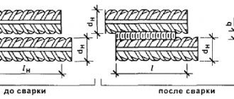
For welding circumferential seams on pipes with a diameter from 25 to 1000 mm, roller welding rotators are actively used. The video explains their operating principle. The product is placed on four rollers, where one or two are driving (the drive is connected to them), and the rest are supporting. The rollers are attached to a common base, slots in which allow you to change the distance between the rotating supports.
The motor drives the drive roller. The rotation speed is changed by a gearbox, which reduces the speed by an order of magnitude, and a thyristor regulator, which slows down the speed to welding speed. Additionally, the torch from the semi-automatic machine can be attached above the joint of the pipes, and the welding start button can be displayed separately. Then the whole process can be automated and performed while standing to the side.
Drum and rotating base models
In other videos you can see rotators, where the basis is a cam spindle (pressure drum) from a lathe. This device has a base on which a shaft with a drum at the end is attached. The pipe is installed in the cams. The mating part is attached to it. Rotation occurs as in the previous version. The disadvantage is the limitation in the diameter of the pipes used (this depends on the width of the cams).
Another model of a welding rotator is a design where it is not the product itself that rotates, but the base underneath it. It is clear from the video that this option is well suited for circular welds for flange welding. By turning the product over, you can weld both inside and outside. Therefore, when deciding on the model of the rotator, it is worth considering what types of seams will have to be made more often (circular at the junction of two pipes or circular for attaching a flange), and then start creating.
Types of manipulators
Models are distinguished by the possibilities of moving the workpieces being welded, the dimensions of the finished units, and weight. Welding manipulators come in several types:
- console;
- carousel;
- lever-sector;
- single-support;
- with two supports (designed to hold long elements);
- universal with partial or complete balancing relative to the tilt axis;
- manipulators-positioners providing marching speed in any position;
- specialized, designed for welding elements of complex configuration.
Equipment is purchased for:
- small-scale production;
- single production of metal products;
- frequent changes in the type of parts being welded.
With continuous production and a large volume of welded products, the purchase of expensive equipment is economically justified. Models are equipped with tracking sensors. They control the size of the gap and the quality of the connection. The dual control system is the key to a reliable weld.
The percentage of defects when using auxiliary rotary equipment is insignificant. The arc is stably maintained, an even bead is formed, and the seam is obtained without sagging or burns. Automated auxiliary devices are needed for connections, the strength and tightness of which determine the safety of operation of the finished welds. When the slightest deviation of the welding point negatively affects the rigidity of the seams.
Welding rotator from what was
2 hours ago, Besprizornik said:
Well, the wire is stuck because the rotation is turned off simultaneously with the device, the feed mechanism and the wire have inertia, the transformer has self-induction. It is necessary to make a delay at least on the delay relay, at least on the PVI, so that the supply and voltage are turned off first and then the rotation stops.
For me, the more I complicate the system, the stronger the syndrome manifests itself, as I call it “Swiss pocket knife syndrome” - when many useful functions with low efficiency are collected in one device. Almost all designers are guilty of this, in an attempt to crossbreed a snake and a hedgehog.
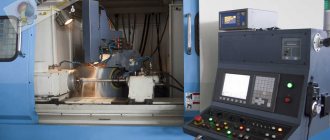
The leading function of my automatic welding machine is body TIG welding. The control logic looks like this: ignition of the arc - start of rotation (IR arc tracking sensor) - counting of angular movement - turning off the arc - crater filling - stopping rotation (after the arc goes out and the IR radiation from the weld pool stops).
The MIG welding logic is based on the functionality of the TIG welding logic: wire feed and arc ignition - start of rotation (IR arc tracking sensor) - counting of angular movement - turn off the arc and wire feed - stop rotation (after the arc goes out and the IR stops). radiation from the weld pool).
Also, TIG welding + cold wire feeding is almost ready (in any case, the logic has already been implemented): ignition of the arc - start of rotation (IR arc tracking sensor) and wire feed - counting of angular movement - command to turn off the arc and turn off the wire feed - crater filling - stopping rotation (after the arc goes out and the IR radiation from the weld pool stops).
And in dreams - TIG welding + hot wire feeding: ignition of the arc - start of rotation (IR arc tracking sensor), applying voltage to the wire and feeding the wire - counting the angular movement - command to turn off the arc, turn off the voltage on the wire and feed wire - crater filling - rotation stop (after the arc goes out and the IR radiation from the weld pool stops).
And as in that joke: “...And now, with all this splendor, we will try to take off.”
Now for annealing. My wire annealing is probably to some extent implemented using the self-inductance of the transformer. In principle, it’s probably not difficult to make a delay if you understand electronics (I don’t). So far, I see on the diagram of the MIG device that the drive and transformer are controlled by one power relay, and the drive motor is connected to the inductor. I haven't figured this out yet.
(wire feed controller diagram is shown only with modification connections)
Modified December 28, 2021 by hvr63