GOST 16037-80 for welded joints using manual arc welding
Manual arc welding of pipes remains one of the most common methods of installing pipeline systems, which are both independent transport and distribution networks and components of process equipment.
High quality joints of pipeline systems is the key to their safe operation. Welding methods, types of joints, geometric parameters and standard dimensions, as well as methods of cutting edges are all regulated in GOST 16037-80 manual arc welding of welded joints. Strict adherence to the requirements of the standard in the design, formation of the technological process and welding of steel pipelines ensures the required level of quality.
- Connection symbols
- Structural elements and dimensions of workpiece edges and seams
- Types of Welds
- Seam leg size table
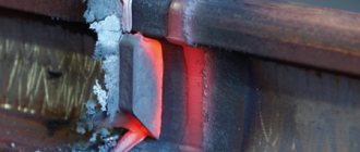
- Cutting pipes for welding
- Welding chamfers
- Conclusion
Connection symbols
The standard describes three types of pipeline welded joints:
- butt, designated by the letter C
- corner, letter U
- overlap, designated by the letter N.
Within each type, the current standard details many subtypes depending on:
- type of weld;
- number of welding sides;
- lining configurations;
- its removability;
- without bevel, with bevel of one or two edges;
- edge section shapes
- suture material cross-sectional shapes
- welding method;
- wall thickness;
- pipe diameter.
Example of type C13 designation.
The symbol, in addition to the type, includes a sign of closed line, welding method, leg parameters and auxiliary symbols . In accordance with GOST 16037 80, argon, submerged arc and gas welding is used. Work in an atmosphere of protective gases can be performed with either a fusible or non-fusible electrode. Typically pipes are made of carbon steel. Stainless alloys are used for work in aggressive environments. Alloys of non-ferrous metals are used less frequently.
Main types of welded joints and seams
- font size decrease font size increase font size
- 1
- 2
- 3
- 4
- 5
Greetings, dear readers. In today's article we will tell you about the main types of welded joints and seams . Many welding specialists call these connections welded, some call them welded , although this does not change the meaning.
In this article they will also be mentioned differently, depending on the turn of phrase, but remember: welded and welded in relation to joints and seams are the same thing.
Welded joints and seams are classified according to several criteria
There are a number of types of welds depending on the type of connection :
- - butt joint seam
- - T-joint seam
- - lap joint seam
- - corner joint seam
Butt joint
A butt joint is a connection between two sheets or pipes at their end surfaces. This connection is the most common due to lower metal consumption and welding time.
The butt joint can be, depending on the location of the seam:
- — One-sided
- — Double-sided
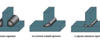
To prepare a joint for welding, depending on the thickness of the products being welded:
- — No beveled edges
- — With beveled edges
One-sided connection without beveled edges involves welding sheets up to 4 mm thick (with the exception of the Laser Hybrid Weld process). It is recommended to perform a two-sided connection of non-beveled edges when welding thicknesses up to 8 mm. In both cases, to ensure high-quality penetration, it is necessary to make a small gap when connecting sheets for welding, about 1-2 mm.
It is recommended to bevel the edges of a one-sided welded joint with thicknesses from 4 to 25 mm. The most popular is the V-type bevel connection. Less popular, but also used are single-sided edge bevels and U-type bevels. To prevent the possibility of burns, the edges are slightly dulled in all cases.
For thicknesses of 12 mm or more, when welding on both sides, it is recommended to use an X-shaped groove, which has a number of advantages over a V-shaped groove. These advantages consist in reducing the volume of metal required to fill the groove (almost 2 times), and accordingly increasing the welding speed and saving welding materials.
T-joint
A T-joint consists of two sheets of paper when a “T” shaped joint is formed between them. As with butt joints, depending on the thickness of the metal, welding is performed on one or both sides, with or without groove. The main types of T-welded joints are shown in the figure.
Some tips for welding a T joint:
- 1. When welding a T-joint of thin metal to thicker metal, it is necessary that the angle of inclination of the electrode or welding torch be about 60° to the thicker metal. As shown below:
- 2. Welding a T-joint (and a corner joint to the same extent) can be greatly simplified by positioning it for welding “in a boat”. This allows welding to be carried out predominantly in the down position, increasing welding speed and reducing the likelihood of undercuts, which are a very common defect in T-weld joints, along with lack of fusion. In some cases, one pass will not be enough, so oscillation of the torch is required for filling joints.
Boat welding is also used in automatic and robotic welding, where the product is tilted using a special tilter to the position required for welding.
- 3. Currently, there are special welding processes for increased penetration. Using them, you can achieve one-sided welding of fairly thick metal with guaranteed penetration and the formation of a reverse bead on the other side. More information about the Rapid Weld welding process can be found here. You can learn about welding equipment for one-sided welding of a T-seam with reverse welding of the bead in the section “QINEO TRONIC PULSE semi-automatic welding machine”
Lap joint
This type of connection is recommended for welding sheets up to 10 mm thick, and the sheets must be welded on both sides. This is done so that there is no possibility of moisture getting between them. Since there are two welding seams in this connection, the time for welding and the consumable welding materials increase accordingly.
Gusset
A corner welding joint is a type of connection between two metal sheets located at right or other angles to each other. These connections can also be with or without beveled edges, depending on the thickness. Sometimes the corner joint is also welded from the inside.
Classification according to other criteria
Welded joints and seams are also classified according to other criteria.
Types of connections by degree of convexity:
- - normal
- - convex
- - concave
The convexity of the seam depends on both the welding materials used and the welding modes. For example, with a long arc, the seam turns out flat and wide, and, conversely, when welding with a short arc, the seam turns out to be narrower and more convex. The degree of convexity is also affected by the welding speed and the width of the edges.
Types of connections by position in space:
- - lower
- - horizontal
- - vertical
- - ceiling
The most optimal position for welding is the lower position of the seam. Therefore, when designing a product and drawing up a welding process technology, this should be taken into account. Welding in the lower position promotes high productivity and is the simplest process to obtain a high-quality weld.
The horizontal and vertical position of the welded joint requires advanced qualifications from the welder, and the ceiling position is the most labor-intensive and unsafe.
Types of welded joints by extent:
- - solid (continuous)
- - intermittent
Geometric characteristics
As mentioned above, the geometry of the seams depends on the type of connection. The main geometric dimensions of the sections of butt and fillet welds are presented in the following figure:
- where S is the thickness of the parts;
- e – width of the weld;
- g – convexity;
- m – concavity;
- h – penetration depth;
- t – weld thickness;
- b – gap in the connection;
- k – fillet weld leg;
- p – height;
- a – thickness.
Read also: Packaging line for bulk products
The geometric dimensions are affected by the type of connection and the thickness of the products being welded. These indicators are shown in the following table.
From the information presented it is clear that all geometric dimensions of welds and parts being connected are interconnected. The length of these elements of welded structures stands out. It depends only on the load on the connection and is completely independent of the geometry of the seam section. The minimum length of the weld must ensure the strength of the connection when the maximum total load is exceeded by 20%. Products are often welded along the entire length of the contact, but in many cases welding is performed in short sections to ensure the necessary strength of the connection. For building structures, the calculation of the length of the weld according to SNiP II-23-81 is carried out based on these criteria.
Calculation of butt weld geometry
The method for checking seams for this type is fully described in the following regulatory documents: SNiP II-23-81 clause 11.1 and SP 16.13330.2011 clause 14.1.14. These documents present different calculation methods, but all of them are derived from the following mathematical formula:
- where N is the maximum tensile or compressive force;
- t – minimum thickness of welded parts;
- lw – seam length;
- Rwy – load resistance;
- γс – tabular coefficient.
With this type of connection, it is welded over the entire length of the contact, therefore the length of the seam is equal to the length of the joints of the parts being welded, reduced by 2t, twice the thickness of the metal. The width of the seam depends on the shape of the edges and the thickness of the parts. Schemes of design options for butt joints are shown in the following figures.
If during welding work materials are used in accordance with Appendix 2 of SNiP II-23-81, no calculations are made, only visual quality control of the connections made is carried out.
Calculation of fillet weld geometry
Calculation of the geometric dimensions of fillet welds under the influence of a load passing along the axis of the center of gravity is carried out along the selected section, the most dangerous in this connection. This may be a calculation based on the cross-section of the weld metal or the fusion boundaries of materials. The figure below shows both sections.
In this type of welded joints, stresses of various types act, but the dominant load is the shear force. Fillet welds are checked using the following formulas.
where N is the maximum tensile or compressive force; βf and βz – tabular coefficients for steel; kf – weld leg length; lw – length; Rwf – design shear resistance; Rwz – the same but in the fusion zone; γс – tabular coefficient of operating conditions; γwf and γwz – the same, but for different operating conditions.
The main geometric characteristic of all fillet welds is the size of their leg, i.e. the thickness along the fusion boundaries. The size of the leg depends on the thickness of the parts, material and welding method. You can select the value of this geometric parameter in the table below.
For steel structures with maximum material flow characteristics above 590 N/sq.mm or a thickness of connected parts above 80 mm, the value of the minimum leg size should be taken in special specifications.
For structures of the fourth group, the size of the fillet weld leg should be reduced by 1 mm for parts with a thickness of no more than 40 mm and reduced by 2 mm for parts thicker than 40 mm.”
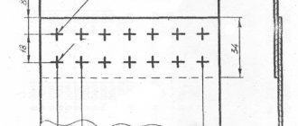
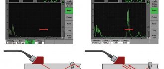
Tools for checking seam dimensions
A weld geometric parameters meter is a specialized tool that can be used to measure the main characteristics of these elements of welded structures. Among the variety of such measuring instruments, the following groups of products can be distinguished: templates, universal meters and devices specialized in measuring one parameter. A professional welder’s kit includes several such tools that allow you to measure both parts prepared for welding and the weld itself.
Conclusion
The above information is relevant for connections made using manual electric arc welding. The dimensions of the weld in semi-automatic welding are calculated using other methods. It should be noted that all geometric dimensions of welds are strictly tied to the thickness of the parts being welded and the maximum load that the entire structure must withstand!
Welds. Types of welded joints
Welded joints
Terms and definitions of basic concepts in metal welding are established by GOST 2601-84. Welded joints are divided into several types, determined by the relative position of the parts being welded. The main ones are butt, corner, T, lap and end connections. To form these connections and ensure the required quality, the edges of structural elements connected by welding must be prepared in advance. Edge preparation forms for manual arc welding of steel and iron-nickel and nickel-based alloys are established by GOST 5264-80.
A butt joint is a connection between two elements adjacent to each other at their end surfaces. In Fig. Figure 2.1 shows the forms of preparation of the end surfaces (edges) and the outline of the welded butt seam obtained as a result of welding.
Types of butt joints
GOST 5264-80 provides for 32 types of butt joints, conventionally designated C1, C2, C28, etc., having different edge preparations depending on the thickness, location of the elements being welded, welding technology and the availability of equipment for edge processing. In Fig. 2.1, a shows the preparation of edges for elements with a thickness of 1-4 mm in the form of a flange, when melted, a seam is formed. In Fig. 2.1, b shows two types of edge preparation without bevelling (cutting): the first is used with a metal thickness of 1-4 mm and one-sided welding, the second with a thickness of 2-5 mm and welding on both sides. When the metal is thick, it is impossible to ensure penetration of the edges to the full thickness by manual welding, so they cut the edges, i.e., bevel them on both or one side. In Fig. 2.1, c shows one of the common types of edge preparation for metal thicknesses of 3-60 mm. The edges are cut on a planing machine or thermal cutting (plasma, oxygen gas). The total bevel angle is (50 ±4)°, such preparation is called one-sided with a bevel of two
Rice. 2.1. Butt joints and seams: a - preparation of edges in the form of flanging (element thickness 1-4 mm); b - preparation of edges without bevel, c - preparation of edges with bevel; 2 - preparation of steel edges with a thickness of 8-120 mm
edges In this case, the value of the bluntness (unbeveled part) “c” and the gap “b” must be maintained, the values of which are established by the standard depending on the thickness of the metal. The figure shows the outline of the main “O” and welding “P” seams. The seam of a butt joint is called a butt seam, and a back weld is a smaller part of a double-sided seam, performed first to prevent burns during subsequent welding of the main seam or applied last, after its completion. The same figure shows the preparation of the edges of steel 6-100 mm thick with a steel backing, which is sometimes used in construction if it is impossible to make a back weld. In addition, it also shows a version of a butt weld with only one part being cut at an angle of (45±2)° and with a vertical part being cut at the same angle.
Figure 2.1, d shows the preparation of steel edges with a thickness of 8-120 mm. Both edges of the welded elements are beveled on both sides at an angle of (25±2)° each, with the total bevel angle being (50±4)°, the bluntness “c” and the gap “b” are established by the standard depending on the thickness of the steel. This preparation is called double-sided with a bevel of two edges. With this preparation, edge processing becomes more complicated, but the volume of deposited metal sharply decreases compared to one-sided preparation. The standard provides for several options for double-sided edge preparation: preparation of only one upper edge, used for vertical arrangement of parts, preparation with uneven edge bevel thickness, etc.
Corner connections
A corner connection is a connection between two elements located at an angle and welded at the junction of their edges. There are 10 such connections: from U1 to U10.
Rice. 2.2. Corner joints and seams: a - with a welding seam (metal thickness 3-60 mm), b - with a steel gasket, b - without a welding seam, d - with double-sided cutting of the adjacent element (metal thickness 8-100 mm)
In Fig. Figure 2.2 shows examples of fillet joints and fillet weld outlines. For a metal thickness of 3-60 mm, the edge of the adjacent element is beveled at an angle of (45±2)°, the main weld is “O” and the weld seam is “P” (Fig. 2.2, a). With the same thickness and through penetration, you can do without a weld seam (Fig. 2.2, b). Often a corner connection with a steel lining is used (Fig. 2.2, c), which ensures reliable penetration of the elements over the entire section. When the metal thickness is 8-100 mm (Fig. 2.2, d), double-sided cutting of the adjacent element is used at an angle of (45±2)°.
T-joints
A T-joint (Fig. 2.3) is a welded joint in which the end of one element adjoins at an angle and is welded with fillet welds to the side surface of another element. The standard provides for several types of such connections: T1 to T9. A common connection is shown in Fig. 2.3, a, for metal with a thickness of 2-40 mm. For such a connection, no bevel of the edges is made, but rather an even cut of the adjacent element and a smooth surface of the other element are ensured.
Rice. 2.3. T-joints and seams: a - for metal with a thickness of 2-40 mm; b - thickness 3-60 mm; c - connection with lining, d - connection with double-sided bevel of edges (metal thickness 8-400 mm)
If the metal thickness is 3-60 mm and the need for a continuous seam between the elements, which is provided for by the design of the structure, the edges of the adjacent element are cut (Fig. 2.3, b) at an angle of (45±2)°. In practice, a T-joint with a lining is often used (Fig. 2.3, c) with a steel thickness of 8-30 mm, as well as a connection with a double-sided bevel of the edges of the adjacent element with a steel thickness of 8-40 mm (Fig. 2.3, d). All these connections with beveled edges of the adjacent element ensure a continuous seam and the best operating conditions for the structures.
Lap joints
An overlap joint is a welded joint in which the elements welded by fillet welds are located parallel and partially overlap each other. The standard provides for two such connections: H1 and H2 (Fig. 2.4). As can be seen from the figure, they differ only in that in the connection in Fig. 2.4, but two ends are welded to the surface of the elements, and in the connection in Fig. 2.4, b - only one end.
Types of Welds
Butt welds are used when welding circumferential joints of pipes in accordance with GOST. Such compounds are designated C1-C53
They are made single- and double-sided, with straight and rounded beveled edges and with boring.
Single-sided seams may have a removable or retained backing, as well as a fusible insert.
Sector connections at pipeline turns are made with beveled edges and are designated C54-C55.
Flange and pipe connections are designated as C56
An example of the designation of a U2 type corner connection.
Fillet welds are designated U5-U21, lap welds H1-H4
Welding technology
A high-quality connection for a fillet weld can be obtained using a boat installation. This is explained by the fact that when placed on a horizontal surface, liquid metal will begin to flow down. This does not happen with a boat stitch, and the seam will not have defects for this reason.
The method got its name from the shape of the stand in the form of the letter “V”, reminiscent of a boat. With any method, the location of the electrode must be such that the arc reaches the edges of both parts, which is ensured by its correct inclination.
Conventional equipment is suitable for welding corner joints. You can use a simple transformer welding machine. The disadvantage is the large size, which causes problems when moving. A more mobile option is an inverter. It is small in size and weight, and has different modes. With its help, arc stability is achieved.
The current is adjusted in direct proportion to the diameter of the selected electrode and the thickness of the products being welded. At higher values there is a risk of burns, and at low values the electrodes may stick. The movement of the electrodes during fillet welding can be oscillatory, which gives excellent quality of the seam.
Other movements are also allowed: in different directions horizontally, in the upper and lower positions.
It is possible to make a ceiling seam if it hardens quickly. For this purpose, electrodes having a refractory coating are used, and welding is performed in a circular motion. This position is uncomfortable for the welder. In addition, if the electrode moves away, the arc immediately goes out, the metal cools, and a decrease in the weld pool threatens a short circuit. Warming up the welding site from below also creates difficulty, so if possible, it is advisable to resort to other options.
When placing a fillet weld when welding at the bottom, the boat method is preferred. It is much easier to perform it in this position than at the top, and the result will be of higher quality, and the risk of lack of penetration and cutting of edges will be minimal. When welding pipes for joining, the socket method is used, which requires a centering device.
A particular problem is posed by fillet welds, welding of which must be carried out in places where access is difficult, in particular when joining pipes. In this case, the following tools and consumables are needed:
- special soldering iron;
- additional nozzles;
- cutter;
- degreasing solution;
- connecting elements.
The pipes are melted with a soldering iron, and their individual elements are connected using nozzles. If a vertical seam is to be made, it is necessary to ensure the fixation of the workpieces. In several places, transverse bridges are used for tack purposes. You should move from bottom to top, using the method of inclined electrodes. Molten liquid dripping down can result in poor performance.
Fillet welds during welding. Distinctive features.
The fillet welding process is characterized by a number of distinctive features. Let's consider the most acceptable methods by which corner joints are welded.
If the seam plane is located at the bottom, then it is better to weld the parts using the “boat” method. This method will allow you to get the highest quality seam and is well suited for beginners in welding work. The product is placed in a V-shape, reminiscent of a boat, hence the name of the method.
When welding with a “boat”, the risk of the formation of such defects as undercutting edges or lack of penetration is practically reduced to zero.
However, such suitable conditions for creating a fillet weld are not always present. Often, at the point where metal products are connected by means of a “boat,” T-welds are formed in such a way that one of the surfaces is strictly in a vertical position, the other in a horizontal position.
In such a situation, it is not easy to obtain a high-quality connection, because in the upper part of the corner and in the horizontal plane of the seam, the part may not be welded. Undercuts may appear on a vertical plane. The cause of their occurrence may be molten metal flowing down.
In order to avoid the occurrence of the above defects, it is important to move the electrode along the welding line with light oscillating movements.
Advice! Wire the electrode using a single seam with an 8 mm leg.
To eliminate the risk of lack of penetration, the initiation of the welding arc should begin at a distance of 3-4 mm from the edge of the leg on the lower horizontal plane. Afterwards, the arc must be directed to the top point of the seam and held there. This way you will get a well-cooked part.
To obtain a high-quality and durable fillet weld, you need to strictly adhere to the sequence of actions. Any welding machine is suitable for creating a corner joint. Do not forget about safety precautions and perform welding work in a protective suit and mask.
Features of welding work
The direct technological map for welding galvanized pipes provides for certain parameters for the work and work process, which must comply with regulatory provisions. The welding process must provide certain characteristics, the purpose of which is to prevent damage to the surface of the galvanized coating during the technological welding process. Thus, electric welding of galvanized pipes involves applying a special flux to the surface of the galvanized coating. This will prevent the zinc from burning out during welding.
Welding galvanized pipes
According to the joint venture welding procedure for galvanized pipes, the following steps are provided:
- At the place of welding work, a flux compound is applied, which has a liquid-viscous technological state.
- During the cooking process, the flux compound transforms into a different structure, melting occurs, and the flux does not emit combustion products and does not evaporate, but welding galvanized pipes is harmful to health, without the use of special protective devices for the welding equipment operator.
- At the end of technological welding, a perfectly smooth and strong seam is obtained at the joint. The surface is completely protected from the occurrence of corrosion processes in the future.
What defects can welding seams have?
Types of defects during welding.
According to accepted standards, defects in seams can be as follows:
- holes, craters, fistulas, which are caused by sparking and the appearance of voids in the weld pool;
- cracks in seams;
- the appearance of uncooked seam fragments;
- inclusion of foreign solid particles;
- deviation of the seam shape from that required by established standards.
It must be borne in mind that most often the cause of the appearance of these defects is a violation of established welding rules and the use of poor quality electrodes. The deterioration of the fillet weld parameters is also facilitated by the smallest air particles that somehow got into the weld pool, and the sudden appearance of stray currents.
Welding profiles at an angle of 90°
When questions arise such as how to weld a frame from a corner, you need to be able to correctly connect the parts at an angle of 90 °.
There are three versions. The first method is that the outer part of one of the shelves of one corner is superimposed on the inner part of the shelf of the second. This method is the simplest, but when it is performed, one corner is higher than the other by the thickness of the shelf.
The second method consists of preliminary cutting the shelf of one of the corners to the height of the shelf. After this, the second corner can be attached flush to the cutout and welded with the first.
The third welding method also allows you to weld workpieces at the same level. To do this, each of the blanks is pre-cut at an angle of 45 °C, after which they are connected at the corners, ultimately forming a right angle.
To weld the frame, you need to take four blanks from angle bars, prepared for welding at right angles using one of the above methods. For preliminary fastening, it is better to use a clamp.
Having combined all the blanks, it is necessary to control the geometric dimensions of the future product. Then, having made tacks at the four corners, again take measurements of the diagonals of the frame, if necessary, adjusting them with light blows of a hammer along the larger diagonal. After this, you can weld the joints.
Downhole pumping units and automation
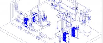
To extract water from wells, surface and submersible electric pumps of a centrifugal operating principle are mainly used. The advantage of this design is the ability to create high pressure in the line, thanks to the use of units with a large number of impellers, which allows increasing the pressure in each subsequent stage.
Household submersible electric pumps can lift water from very great depths (about 200 meters), while surface types are used in sources with a water surface at a depth of up to 9 meters from the surface of the earth. To increase the intake depth of surface models, built-in or submersible ejectors are sometimes used, although their efficiency decreases significantly.
Rice. 11 Centrifugal electric pump
Hydraulic accumulator, relay and pressure gauge
To automate the operation of water intake pumping equipment, an automation system for a well or a pumping station is used, consisting of the following devices:
- Hydraulic accumulator. It is a voluminous metal tank with a rubber bulb inside, which fills with water when the electric pump is turned on. The device allows you to avoid water hammer in the system and optimizes the operation of the electric pump, reducing the number of its on and off cycles.
- Relay. The main element of the automatic control system is a pressure switch, which is connected to the line using a fitting. When pressure appears in the system above its settings, the built-in membrane inside the relay housing through a mechanical system interrupts the supply voltage to the electric pump and it turns off. After consuming water, when the pressure in the system drops, the relay closes the contacts and turns on the electric pump.
- Pressure gauge. The device is one of the main elements in any plumbing system; it allows you to control pressure and configure equipment.
Rice. 12 Automation in the electric pump control system
The design of water wells is not very complicated; the main internal elements that are installed during drilling are casing pipes and a filter in the bottomhole area. To collect water after installing a well, additional equipment and engineering systems (caisson, head, adapter) are used, which make it possible to effectively connect the electric pump to the source, taking into account its location and type.