What is a weld seam
To begin with, let’s define the concepts of “welding seam” and “welding joint”, because some sources consider them to be one and the same thing, others separate the formulations.
The shortest definition: a weld is a permanent connection by welding.
The second option reveals the physics of the welding process as such: a weld is a section in which two or more parts are connected as a result of crystallization or deformation of a substance, or one and the other together. One way or another, it is more logical to take welding seams and joints as one and the same process.
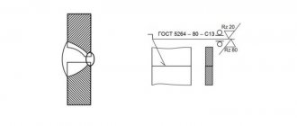
One of the oldest and most famous standards among specialists is “GOST 5264 – 80 Manual arc welding. Welded connections." This GOST was put into effect back in 1981, it still copes with its tasks perfectly: the main types of welds, their sizes, structural elements and instructions on how to correctly lay a weld are clearly listed. An excellent example of a document that does not need adjustments over time.
Decor
The document is drawn up by the organization conducting the installation work . It is compiled by the production and technical department on the basis of design and working documentation transferred to installers from the customer or directly from the designer, if provided for by the contract.
Based on the 3D model of the object presented by the designer, the technical department begins the formation of a weld pattern.
Simultaneously with drawing up the scheme, other related documents are also prepared:
- summary table of joints;
- acts of welders performing test welds and assigning them a personal mark;
- certificates of welding work.
Without a complete set of documents, the facility cannot be accepted for operation
Types of welding seams
Types of welding joints.
Like welding methods, types of welding seams fall under a strict classification according to different criteria:
- The method of connecting parts;
- Position during welding;
- Seam length;
- Location of the force acting on the seam.
The most popular and important types of seams are grouped according to the method of joining parts:
- Butt.
- Angular.
- T-bars.
- Overlapping.
Important! Whatever type of weld seam you choose, you need to remember and follow one simple rule: no rust on the metal! Pre-treatment with a file or sandpaper is mandatory, the issue is no longer discussed.
Butt seams
Classification of electrodes for welding.
Types of welded joints include both very popular methods and rare ones. Butt methods can be considered highly popular: they are used when welding sheet metal or pipe ends. The fundamental requirement for the butt method is rigid fixation of the parts to be joined with a gap of 1 - 2 mm, which is filled with metal during the welding process.
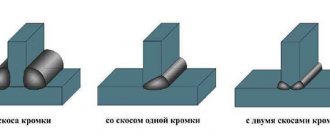
The most important “butt” issue is the edges of the parts that will melt and join. Or rather, the way to process these edges. The butt connection is considered one of the most reliable and economical in terms of strength. This is especially true when cooking on both sides. Preliminary preparation of the edges is an important component of a high-quality seam. All 32 types of butt joints with edge processing options are set out in the GOST 5264-80 standard.
Here are some examples:
- If the metal sheet is thin - less than 4 mm, no pre-treatment is required; this is a family with symbols C1, C2, C3.
- If the sheet thickness is between 4 and 12 mm, the seam can be welded on both one and both sides. But in this case, edge processing by stripping is necessary. It all depends on the requirements for welding quality. If you choose to weld on one side, you will have to make multiple passes to fill the seam. If high quality is required, you need to peel and cook on both sides. Strippings come in the form of V or U. There are many options, all are listed in GOST, for example, symbols C28, C42.
- If the metal sheet is thicker than 12 mm, only double seams are used with edge processing on both sides in the form of the letter X. V or U shapes for stripping edges with large thicknesses are unprofitable: too much metal will be required to fill them. And this reduces the speed of the process and increases the consumption of electrodes. Symbols C27, C39, C40.
There is no need to outline in this review all the possible methods of welding metals using the arc method, depending on the thickness of the sheets and methods of processing the edges; no one will do this better than GOST 5264-80. Therefore, the best decision would be to refer to it and recommend this excellent example of technical instructions for careful study.
In short, according to GOST, the joint family is divided into:
- Single-sided and double-sided without edge treatment;
- With processing of one of the edges;
- With processing of both edges;
- Sawing in the form of a V or X;
- With double-sided processing of both edges.
T-joints
The T-type method is cut into the shape of the letter “T”: the end of one part is welded to the side surface of another part. Most often, the elements are located perpendicular to each other. GOST 5264-80 describes 9 T-type types: T1 to T9. For a high-quality T-joint, deep melting is required, which is performed using automatic welding. If welding is done by hand, careful processing of the edges is required.
An interesting feature of deep fusion T-welds: they are stronger than the base metal. The strength of fillet welds (see below about them), on the contrary, is less than the base metal. These kinds of differences must not only be taken into account, but calculations must be made in advance. The concept of “calculation of welded joints” is included in a special section of technical mechanics, which is studied at engineering faculties.
These strength-of-materials tasks take into account the main features and disadvantages of welding joints: uneven strength, uneven heating and cooling processes, as a result, possible warping, residual stress or hidden defects.
Corner connections
Scheme for creating a vertical seam.
In some sources, fillet welds during welding are described as part of T-welds. They are as easy to describe as T-bars: the corner profile resembles the letter “G”, and in GOST 5264-80 they are designated with the initial letter “U”: from U1 to U10.
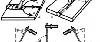
Despite the apparent simplicity of welding a corner joint, sometimes difficulties arise: metal flows from a corner or vertical surface onto a horizontal one. The solution to this problem is to control the movement of the electrode in order to maintain the correct angles of inclination and so that this movement is smooth. In this case, you will receive a high-quality, evenly filled seam.
An excellent way of high-quality corner welding is the method called “boat welding”: the parts are located at right angles to each other, the length of the seams is 8 mm or more.
If welding corner joints involves sheets of metal of different thicknesses - thin and thick - the electrode should be located at an angle of 60 degrees to the thicker part so that more heating is applied to it. Then the thin metal will not burn out.
Welding fillet welds requires compliance with the rules of the geometry of welding joints.
The main geometric criteria are as follows:
- Width - the gap between the edges of the fusion of metals;
- Curvature – the gap at the point of maximum concavity;
- Convexity – the gap at the point of maximum convexity;
- The root of the joint is the edge farthest from the profile (the actual wrong side)
Welding a fillet weld will be most optimal with a concave level shape. This is explained by the risk of incomplete welding of root fillet welds to the full thickness. When it comes to choosing the most durable option possible, there are many different factors to keep in mind.
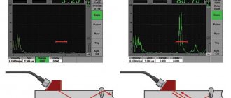
Main types of welds.
Basic standards of electric welding for the size of the seam:
- Arc voltage;
- Pace of work;
- Wire cross-section size;
- Magnitude, density, polarity of voltage.
For example, as the current increases, the penetration depth increases (the size does not change). But at a time when the arc intensifies, the seam expands and, as a result, the depth of penetration decreases.
If the cross-sectional size of the welded wire decreases, the current in the wire increases, the penetration depth increases, and the seam itself decreases in size. There are many examples of the optimal combination of welding factors. All types of welded joints contain the main requirement - not to violate the execution technology, plan in advance and calculate the values of all input parameters.
Overlapping seams
Overlap joints: surfaces are parallel to each other, partially overlap each other, welded in a corner manner. These are the easiest stitches to make - a great start for beginners.
Lap joint - diagram.
All types of overlap welds have a strict limitation on the thickness of the sheet metal - it should be no more than 8 mm. Here it is important to find the correct angle of inclination of the electrode - the range is from 15 to 45 degrees. In GOST, overlap joints are conventionally designated as H1 and H2.
When working with two workpieces, one-sided turned welding is often used, which has a serious drawback: gaps form between the parts. Moisture and corrosion become the main enemies with this method. The result of this kind of defect is described in one word - fragility.
However, lap joints have a very wide range of applications, here are a few examples:
- Installation of lightweight structures such as pavilions or stalls;
- Installation of billboards and other structures;
- Assembly of awnings and awnings.
In addition, the PPR should provide for:
- measures to ensure the required quality of preparation and assembly for welding of welded edges, as well as the scheme for their fastening and the necessary technological equipment for this;
- permissible metal temperature at which welding of joints is possible without heating them, as well as permissible wind speed in the welding zone;
- conditions for ensuring the required range of cooling rates of welded joints of tank structures during welding;
- instructions on the technology of welding work in winter conditions (if this is provided in accordance with the work schedule).
In cases where the CM working documentation provides for heat treatment of any welded joints of the tank, the PPR should develop a technology for its implementation, including a method, heat treatment modes, and instructions for quality control of heat-treated joints. The PPR must develop a quality control program for welded joints, including methods and scope of control of each welded joint of the tank.
Examples of similar educational works
FEATURES OF WELDING STAINLESS STEEL FOR MANUFACTURING MACHINE PARTS
... concentration of thermal energy. Abstract on the topic “Features of welding stainless steels for the manufacture of machine parts” Purpose: To determine the main features of welding stainless steels. Objectives: Study the literature on steels; [Electronic resource]//URL: ...
Gas welding technology
... and membranes, etc. Preparing the generator for operation: pour water into the safety ... The main parameters of gas welding are the type and power ... the post) is equipped with everything necessary for welding work. At a stationary welding station...
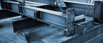
K3t column assembly and welding technology
... for general and control assemblies, provision of parts for assembly, installation and welding during installation) and technological capabilities ... or multi-profile flat transverse frames formed by columns and building trusses with spans of more than 18 m for ...
Design of a technological process for the manufacture of welded metal structures...
... mass production of welded products of the same type. Possibility of widespread use in welded structures… a requirement. The metal structure “Tank with flanges” does not experience significant external mechanical loads (static...
Compare, evaluate
Of the above options, butt welding is considered the most reliable and economical. In terms of current loads, they are almost equal to whole elements that were not welded, in other words, to the base material. Naturally, such strength is achieved only with adequate quality of work.
At the same time, it must be remembered that the reliability and efficiency of the method does not mean that it is easy to implement. Requirements for edge processing, adjustment of many factors to the conditions of a specific welding, certain restrictions in application due to the shape - all this requires strict professional discipline.
Welding butt seams.
T-joints (including corner ones) are also quite popular. They are especially often used when welding massive structures.
The simplest ones to perform are overlapping joints. They do not require edge processing, and general preparation is also much simpler. Very popular in welding sheets of small thickness (thickness up to 60 mm is allowed). Simplicity does not mean efficiency: excessive consumption of deposited and base metals is a common situation for such options.
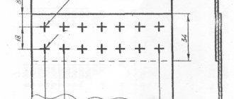
Vertical wall connections.
Vertical wall connections must be butt joints with full penetration through the thickness of the sheets (Figure 5.2.1).
Vertical connections of sheets in adjacent wall chords must be offset relative to each other by a distance of at least 8t
, where
t
is the largest of the thicknesses of the sheets of adjacent belts. For tanks of classes II and III, when making walls from rolled panels, vertical factory and assembly butt joints without displacement are allowed. The distances between the seams of pipes, reinforcing sheets and wall seams must be at least: to vertical seams - 250 mm, to horizontal seams - 100 mm. The vertical connections of the first wall chord must be located at a distance of at least 100 mm from the joints of the bottom edges.
Seams according to position in space
The next classification criterion is the position of surfaces in space. There are four such provisions:
- Bottom seams
- Horizontal
- Vertical
- Ceiling
If it were possible to choose, experienced craftsmen would choose welding in the lower position. This is the most convenient method, and the weld pool is better controlled. A suitable method for debut works of beginners - there are practically no difficulties here. But the other three spatial options are associated with technical nuances and special requirements for execution.
When welding in a horizontal position, the main problem is gravity - because of it, the metal simply slides down. Such compounds can be cooked both from right to left and from left to right, as is convenient for you. But the rule for using an electrode is the same for everyone: its angle of inclination must be large enough. Of course, when selecting an angle, you need to take into account the current parameters and the speed of movement, everything is interconnected.
Choose, try, the main thing is that the bathtub does not tend to fall down. If the metal still drains, you need to reduce its heating - this can be done by increasing the speed of movement. The second option is to periodically tear off the arc so that the metal cools at least a little. The arc lift method is more suitable for beginners
Classification of seams by position in space.
In vertical connections, the same problem is the force of gravity, but here it is not the entire bath that tends down, but drops of metal. Usually in such cases they take a shorter arc. The seam can be welded in any direction. In the Welding Certification Regulations RD 03-495-02, these options are designated as “welding position B1” - vertical from bottom to top (this method is more convenient). “Welding position B2” is vertical from top to bottom, it is used less often, since strict control of the weld pool is required here.
The ceiling connection is the most difficult in the subgroup, which will require real skill. There are no other options in the position of the electrode - keep it only at a right angle to the ceiling. Make the arc shorter, the speed of the circular motion should be constant. In this case, the release of gases and slags is difficult, and it is difficult to keep the melt from flowing down. Even if the craftsmanship is at the proper level, and all technological requirements are met correctly, the ceiling method is inferior in strength and overall quality to welding seams in all other positions.
Rice. 5.2.1 Vertical butt joints of the wall.
A)
without cutting edges;
b)
with bevel of two edges;
V)
with two beveled edges;
G)
with curved beveled edges.
15 pages, 7446 words
Defects in welded joints. Acetylene generators
... established standards and technical requirements that reduce the strength and operational reliability of welded joints and can lead to destruction of the entire structure. The most common defects... when welding vertical surfaces with horizontal seams as a result of liquid metal flowing onto the edges of the cold base metal. They can be local, in the form of individual frozen...
We cook pipelines, special requirements
Only experienced, certified and highly qualified craftsmen are allowed to work with industrial pipelines.
Pipe connections belong to the vertical method with all the “vertical” nuances. The peculiarity lies in the angle at which the electrode is held, this is an angle of 45 degrees. The width of the pipe seam can reach 4 cm, it depends on the thickness of the pipe itself. There are separate standards for this type of welding, for example, GOST 16037-80 describes the dimensions of seams for various connections of pipeline structures.
Shape and extent
The shape of the seam can be convex, even (flat). Sometimes it becomes necessary to make a concave shape. Convex joints are designed for increased load.
The concave areas of the alloys withstand dynamic loads well. Flat seams, which are made most often, are characterized by versatility.
The length of the seams is continuous, without intervals between the fused joints. Sometimes interrupted stitches are sufficient.
An interesting industrial variation of the intermittent seam is the joint formed by resistance seam welding. It is done on special equipment equipped with rotating disk electrodes.
They are often called rollers, and this type of welding is called roller welding. Continuous connections can also be made using such equipment. The resulting seam is very strong and absolutely airtight. The method is used on an industrial scale for the manufacture of pipes, containers, and sealed modules.
Defects and sewing defects
The most common defect in a beginner’s work is a crooked seam with uneven filling. This picture is the result of uneven guidance of the electrode; it literally dances in the hands of the young master. Here you will need perseverance and work: with experience, all this passes without a trace. The second most common mistake is the incorrect choice of current strength or arc length, which leaves “undercuts” or uneven filling. With some defects, aesthetics suffer more, with others - strength.
Lack of penetration - insufficient filling of the joint of parts with metal. It needs to be corrected, since we are talking about the strength of the connection.
In what cases does lack of penetration appear:
- Poor quality processing (or lack thereof) of surface edges;
- The current is too weak;
- Electrode movement too fast.
An undercut is an unnecessary groove along a seam. The diagnosis is simple: choosing an arc that is too long. The treatment is also clear: either a shorter arc, or a higher current intensity.
Examples of electrode movement patterns.
A burn-through is a banal hole in a seam for the following reasons:
- Wide gap between edges;
- The current is too high;
- Low electrode speed
And here we are looking for the optimal ratio of three components: current, gap width, electrode movement.
Pores and nodules are multiple small holes. This is a critical defect that affects the strength of the connection.
Causes:
- Dirt and rust on metal;
- Oxygen reaching the molten metal (in a draft);
- Poor quality edge processing;
- Low quality electrodes;
- Use of filler wires;
Cracks are serious violations of the integrity of the seams. They appear after the metal has cooled and are essentially harbingers of the destruction of the seam itself. In this case, only new welding or complete removal of the old seam and re-applying a new one will save.
Design rules
The pipeline welding diagram must contain the following information:
- Object name;
- pipeline class;
- pipe parameters: alloy material, diameter and wall thickness;
- transportable medium;
- snapping to reference points.
Each joint on the diagram must have its own unique number . Sometimes continuous numbering of welded joints throughout the entire project is used, then the designation takes the form “E12.123”, where before the dot there is an object identifier, and after the actual joint number on a specific diagram.
The stage of forming a diagram of welded joints from a 3D model. The drawing is simplified, fittings and equipment are replaced with symbols.
In addition, the diagram can indicate the distance between adjacent joints and supporting objects, such as turns, reinforcement, supporting metal structures or process equipment. This is mandatory in two cases:
- the pipeline is covered with a layer of insulation;
- the site runs underground or is hidden in the walls.
If necessary, markings (for example, in the event of an accident, planned repair or inspection) will help you quickly and without unnecessary costs and damage to structures find the joint in the event of repairs, without resorting to additional documentation.
Joints in a schematic drawing can be of two types:
- rotary;
- non-rotating.
Rotary welds include welds made by a welder with a section of pipe rotated along the longitudinal axis at a certain angle . Usually this is an angle that is a multiple of 90°. Such seams are welded in the “bottom” position. Such seams are of higher quality and more durable, since the work is carried out in a position convenient for welding. Analysis of statistical data shows that the frequency of detection of defects in such seams is significantly lower than in non-rotating ones. welded joints.
A fixed joint is welded without rotating the pipe to a convenient position . On the contrary, the welder has to follow the seam around the pipeline, including in disadvantageous positions: seams with a positive and negative slope, as well as vertical and ceiling ones. In this case, it is necessary to change the inclination of the electrode, its speed, welding current and other important operating modes several times.
In this case, the seam is welded in several stages, which negatively affects its strength and durability. Working in such conditions requires a worker with extensive experience and high qualifications.
Near each joint, the details of the welders who welded it are indicated (full name, personnel number or personal mark number).
The document also notes connections for which quality control will be required by non-destructive means (ultrasound, x-ray, etc.). For particularly important objects associated with high pressures and temperatures, aggressive environments and other factors, control is carried out for all joints.
The location diagram of welded joints indicates the joints at which non-destructive testing (ultrasonic, radiographic) is required. All joints are subject to visual inspection.
When drawing up a document, the same coordinate system is used as in other design and working documentation.
Important! The schema data and the summary table must match the Work Log data in the following parameters:
- connection numbers;
- pipe parameters;
- Full name of welders and personal mark numbers
- duration of work.
If the dimensions and slopes of the constructed object correspond to the design values, the inscription is written on the diagram: “There are no deviations from the design parameters.” Otherwise, a designer's inscription coordinating these deviations or a link to a separate document - an act of approval - is required.
The diagram is included in the object passport , drawn up on high-quality media and using materials that guarantee long-term storage.
After completion of the work, all documentation is checked for completeness and correctness of execution and filling. After verification, the documents are handed over to the archive.
Some tips for welding various joints
Is it possible for a beginner to learn how to apply high-quality sutures on his own? Yes, without a doubt. Some sources use the word “with ease.” It’s better not to promise ease, because welding has never been an easy or safe process. But it is quite possible to determine consistent and feasible steps on your own. The principle is from simple to complex. Of course, all the main types of welding joints have their own secrets and subtleties that need to be mastered.
For beginners, electric arc welding is best suited. The best option is to start studying under the supervision of an experienced mentor. But if this is not possible, there are a huge number of videos on the Internet showing all the actions and detailed explanations for them.
Single-pass and multi-pass seams.
The main initial stage is the competent preparation of the necessary equipment.
Here's what you need to prepare for electric arc welding:
- Welding equipment (various types);
- Electrodes with the correct diameter (extremely important!)
- Hammer for cleaning the cooled seam;
- Metal brush for the same cleaning of the welded area
- Mask, special light filter.
The requirements for clothing are simple: it must be thick, with long sleeves and gloves. A rectifier with a transformer will come in handy (especially if the equipment is old).
https://www.youtube.com/watch?v=AoRkP_DqEKs
Bottom line
The main types of welded joints are placed within the framework of a precise and clear classification with symbols and a detailed description of technological features and tips. One of the most popular standards is GOST 5264-80, which describes almost all types of welding seams.
You can learn welding on your own according to the principle “from simple to complex.” A “simple” starting point for execution is to take overlapping seams. You can finish with aerobatic work - welding with ceiling-mounted surfaces. We wish you pure metal, good orders and a working mood.
Weld joint processing
When welding, slag is formed. If slag inclusions get into the weld, its quality deteriorates. All slag deposits must be cleaned off.
If welding is performed in several passes, then the seams are cleaned after each welding stage. In this case, any methods are used. First, the welded parts are hammered and cleaned with a stiff brush.
Then a rough cleaning is carried out. Small parts are cleaned with special knives or grinding wheels. Large blanks are cleaned on machines. At the final stage, the welded joint is polished.
Often a fiber wheel of a grinding machine is used for this. There are other ways to polish welded joints.
Welding is constantly evolving. New materials are appearing and technology is improving. It is necessary to follow the news in welding to learn a lot of new and interesting things.