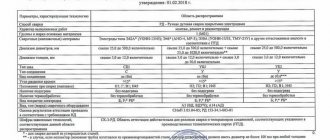
Contents of the check
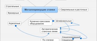
The types of activities related to maintenance procedures and their frequency are determined by the procedure set out in the current standards and regulations. Moreover, different types of equipment have their own standards, but there are also general maintenance rules.
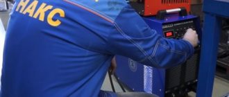
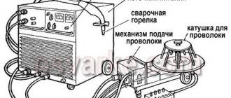
Electric welding machines, being essentially electrical installations, must be operated and also undergo maintenance in accordance with the current standards, which for them are the Rules for the Technical Operation of Consumer Electrical Installations, which contain the corresponding section. According to these rules, inspection of welding equipment should be carried out to the following extent:
Carrying out external inspection of devices;- control switching on in idle mode for at least 5 minutes;
- measurements of insulation resistance values;
- monitoring the serviceability of protective grounding circuits;
- carrying out high voltage tests.
Periodic checks, including monitoring of insulation resistance, external inspection and control switching on as part of maintenance, should be carried out when putting welding equipment into operation after a long break in operation.
This must also be done if visible traces of mechanical or electrical damage are detected, but in any case, no less than once every 6 months. Personnel carrying out such checks must make entries in the prescribed form in a journal specially designed for this purpose.
Test standards carried out during maintenance must comply with those set out in Appendix 3 of the Rules, as well as the instructions for operation and maintenance.
Welding Equipment Test Parameters
When checking welding equipment, tools and fixtures, it is necessary to compare the results obtained with the data given in the table:
| Purpose of equipment, tools, devices and main verified indicators | Technical requirements | Possible deviations from requirements |
| I. Equipment for resistance butt and spot welding | ||
| 1. Primary voltage | 380 V | — 15 V + 25 V |
| 2. Compressed air working pressure | 5.5 ati | — 1 ati |
| 3. Cooling system tightness | Full | – |
| 4. Water circulation in the cooling system | Unhindered, with the flow rate specified in the equipment passport or in Appendix 2 of the Instructions | – |
| 5. Length of the upsetting mechanism lever for manually driven butt welding machines | When welding reinforcing steel class A-IV not less than 1200 mm | – |
| 6. Length of the handle of manual clamps of rods in the electrodes of butt welding machines | Not less than 500 mm | – |
| 7. Installation of electrodes | a) In butt welding machines - coaxial arrangement of the welded rods | – |
| b) In spot welding machines with double-sided current supply - coaxial arrangement of the upper and lower electrodes | – | |
| c) The same, with one-sided current supply - the axes of adjacent electrodes should be located in the same vertical plane parallel to each other | – | |
| 8. Attaching the electrodes | Reliable, no backlash | – |
| II. Arc Welding Equipment | ||
| 1. Current power supply type | Depending on the welding method in accordance with the recommendations of the Instructions | – |
| 2. Connecting the power source to the welding stations | To independent electrical assemblies that receive current from individual feeders at the nearest transformer station | – |
| 3. Current voltage supplying the primary winding of the welding transformer | 380 V | — 15 V + 25 V |
| 4. Generator open circuit voltage during semi-automatic welding | 2–5 V higher than initial welding voltage | – |
| 5. Attaching flexible current supply cables (to transformers, to each other, etc.) | Tight, with lugs held together by bolts or other means that ensure good electrical contact | – |
| 6. Cross-sectional area of flexible current carrying cables | Depending on welding current: up to 200 V – 25 mm2 | 2 × 10 mm2 |
| 200–300 – 50 mm2 | 2 × 16 mm2 | |
| 300–400 – 70 mm2 | 2 × 25 mm2 | |
| 400–600 – 95 mm2 | 2 × 35 mm2 | |
| 7. Flexible cable length | No more than 30 m | – |
| 8. Insulation of flexible cables | No violations | – |
| 9. Arc polarity when welding with direct current | In accordance with the recommendations of the Guidelines | – |
| 10. Cleanliness of the contact surfaces of the electrodes (jaws) and the current-carrying electrode of the table in machines for submerged arc welding of T-joints of embedded parts elements | Cleaning to a metallic shine | |
| 11. Wire feed speed | Depending on the diameters of the wire and welded rods in accordance with the requirements of the Instructions | |
| 12. Uniformity of welding wire feeding | Feed without jerks or delays | |
| 13. Diameter of the hole in the tip of the semi-automatic holder | The tip is selected depending on the diameter of the welding wire. The hole diameter of the tip channel should be 0.3 mm larger than the wire diameter | |
| 14. Development of a channel in the tip of the holder | Local development no more than 1.5 mm | The tip can be rotated so that the wire is pressed against the undeveloped area of the channel |
| III. Tools (electrodes) for resistance butt or spot welding | ||
| 1. Geometric dimensions | Depending on the diameter of the welded rods in accordance with the requirements of the Instructions | When spot welding, the increase in the diameter or dimensions of the oval working surface in plan due to deformation of the electrodes should not exceed 3 mm |
| 2. Shape of electrodes for spot welding | Depending on the type of elements being welded in accordance with the recommendations of the Instructions | – |
| 3. Shape of sockets in electrodes for butt welding of reinforcing steel | Depending on the class of reinforcing steel in accordance with the recommendations of the Instructions | – |
| 4. Condition of the working surfaces of the electrodes | a) Clean to a metallic shine. b) Absence of a dent - a groove at the point of contact with the rods. c) Surface shape in accordance with the requirements of the Instructions | Dents no more than 1.5 mm deep |
| IV. Accessories for arc seam welding or pool welding | ||
| 1. Type of electrode holder for multi-electrode arc welding pool | Special, in accordance with the recommendations of the Instructions | Ordinary |
| 2. Type and dimensions of inventory forms | Depending on the position and diameter of the welded rods in accordance with the recommendations of the Instructions | – |
| 3. Wear and tear of inventory forms | The gap between the cylindrical surfaces of the rods and molds is no more than 2 mm, and the wall thickness is reduced by no more than 0.15 d | – |
| 4. Condition of the internal (working) surface of copper molds | Free from slag | – |
Repair and preventive maintenance
Repair and maintenance of devices intended for welding work must be carried out by specialists with sufficient qualifications who are part of specialized units.
If the enterprise does not have repair personnel of the appropriate level, the work must be performed on a contractual basis by repairmen from specialized organizations.
Welding equipment, along with thermal equipment, belongs to objects that are a source of increased danger. For this reason, specialized regulatory documents have been developed regulating the procedure for monitoring its condition. These provisions are formulated in the guidance document RD 34.10.127 - 34.
Reasons for deterioration of insulation
During the operation of electrical equipment, as a rule, the insulation deteriorates. The main reasons for the deterioration of insulation are the following:
- electrical - mainly local (point) insulation breakdowns associated with ionization at high electric field strength;
- thermal overloads – as a result of increased loads, the process of overheating of current-carrying parts of electrical installations or cores of cable lines and electrical wiring occurs, which leads to changes in insulation properties. For example, rubber dries out and cracks, and plastic melts;
- mechanical loads - occur in cable lines laid in the ground as a result of changes in the temperature surrounding the cut, freezing and thawing of the soil, or in ceramic insulators as a result of internal stresses. They manifest themselves in rips and tension in cables and cracks and chips in insulators.
- exposure to aggressive environments and water.
- incorrect actions of personnel.
Ultimately, deterioration of insulation can lead to single-phase and multi-phase short circuits, and in case of incomplete short circuits (without metal contact) - to fires.
Thus, it becomes clear why regular measurements of insulation resistance are necessary.
Inspection frequency
In accordance with this document, all repair and preventative measures related to the maintenance of welding and thermal equipment must be carried out in direct accordance with the schedule approved by the chief technical specialist of the enterprise.
The importance of timely verification of technical measuring instruments that are equipped with welding machines is especially emphasized. For this purpose, it has been established that the specialist responsible for metrology at the enterprise should take part in the preparation of maintenance schedules for welding equipment.
Thus, a planned shutdown of equipment for repairs or maintenance should be timed to coincide with the delivery of measuring instruments for verification.
According to the standards established by this guidance document, as part of maintenance, it is necessary to regularly carry out activities to monitor the technical condition of equipment:
- AC and DC welding machines (transformers and rectifiers) are inspected twice a month;
- welding inverter converters are subject to inspection once a week;
- machines for automatic and semi-automatic welding are inspected daily.
The fact of the inspection (inspection), as well as the result obtained, is recorded in a journal of the established form.
Basic terms and definitions
Equipment maintenance and repair system - A set of interrelated tools, maintenance and repair documentation and performers necessary to maintain and restore the quality of the products included in this system.
Maintenance of welding equipment (Preventive maintenance, Maintenance) – A set of operations to maintain the serviceability of the equipment.
Repair – A set of operations to restore the serviceability or performance of products.
Frequency of maintenance (repair) - The time interval or operating time between this type of maintenance (repair) and the subsequent type of the same or another of greater complexity. (Note: the type of maintenance (repair) is understood as maintenance (repair), allocated (allocated) according to one of the characteristics: stage of existence, frequency, volume of work, operating conditions, regulation, etc.).
Periodic maintenance – Maintenance performed at operating hours or time intervals established in the operational documentation.
Regulated maintenance – Maintenance provided for in the regulatory, technical or operational documentation and performed at the frequency and to the extent established therein, regardless of the technical condition of the product at the time of the start of maintenance.
Planned maintenance – Maintenance, which is carried out in accordance with the requirements of regulatory, technical or operational documentation.
Overhaul - Repairs performed to restore the serviceability of a product to full or close to full service life with the replacement or restoration of any of its parts, including basic ones.
Medium repair – Repair performed to restore serviceability or partially restore the service life of a product with the replacement or restoration of components of a limited range and monitoring the technical condition of the components.
Medium repair – Repair performed to restore serviceability or partially restore the service life of a product with the replacement or restoration of components of a limited range and monitoring the technical condition of the components.
Scheduled repairs – Repairs that are carried out in accordance with the requirements of regulatory and technical documentation
Special checks
A special form of inspection is established when monitoring newly received equipment, equipment that has been repaired, and equipment that has been idle for more than three months.
In these situations, the availability and completeness of the technical operational documentation of the device (passport, operating instructions, diagrams) is checked.
A visual inspection of the technical condition of the equipment is carried out, if the equipment is new, excess lubricant is removed, transport fasteners are removed, and if any, loose bolted connections are pulled.
The presence of a valid (that is, not expired) mark (sticker) of the verification organization on the housings of measuring instruments is checked. If necessary, a note about the verification period is made in the corresponding column of the equipment passport.
The level of electrical insulation resistance is measured. It is also necessary to turn on the equipment to determine its operating status.
Insulation resistance measurements are carried out between windings (for transformers and rectifiers), as well as between each winding and the equipment frame.
In this case, you should follow the recommendations set out in the technical documentation of the device. If the operating instructions do not contain a description of the testing methodology, they should be carried out in accordance with GOSTs. Thus, automatic welding machines are tested in accordance with GOST 8213 standards.
Semi-automatic welding devices - in accordance with GOST 18130. Tests of devices based on a welding inverter are carried out in accordance with GOST 7237. Alternating current devices (transformers) - in accordance with GOST 7012.
As part of the service, electric generators are subject to testing in accordance with GOST 304. Devices using rectified welding current - in accordance with GOST 13821.
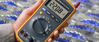
The procedure for measuring insulation resistance.
Who can carry out periodic measurements of insulation resistance?
According to the Labor Safety Rules during the operation of electrical installations, this is a specially trained employee from among the electrical personnel.
Employees of ETL, which has a registration certificate from Rostekhnadzor with the right to carry out this type of work. Based on the measurement results, a report is drawn up indicating the identified defective equipment, recommendations for eliminating the identified defects, and protocols are issued for electrical equipment, cable lines and wiring that have undergone insulation resistance measurements, with a conclusion on the compliance of the equipment parameters (in a particular case of insulation) with the requirements of regulatory documentation and suitability for further use.
The protocol issued by a registered ETL is a legal document confirming the suitability of electrical equipment for use.
You can order the service of checking and measuring insulation resistance in our electrical laboratory. By phone, ProfEnergia specialists will answer all your questions!