Connection calculation method
There are several types of metal bonds and for each of them the calculation of the weld is carried out individually. Depending on the location of the parts being welded, connections are divided into:
- angular , when the parts to be welded are located perpendicular to one another. To increase the strength of the structure, it is necessary to correctly determine the maximum forces on the fillet weld;
- butt. Here the ends of the parts are connected, with one part acting as a continuation of the second. This method of coupling is accompanied by minimal stress concentrations and is considered the most rational. Seams can be straight or oblique;
- overlap , in which the elements of the parts slightly overlap one another. As a rule, this technology is used when welding metals whose thickness does not exceed 5 mm, when it is necessary to strengthen the seam;
- T- bars Externally they resemble corner ones. The fastened elements are located at right angles to each other, but are connected at the ends. In the production of metal structures, such joints are used quite often. They are characterized by ease of execution, cost-effectiveness and high strength. For high-quality execution of this type of connection, a manual will be a good assistant; the calculation of a T-weld joint can be performed using it with impeccable accuracy, and possible errors can be avoided.
How is the cross-section of a fillet weld or other types of joints calculated? There are generally accepted formulas that are used to calculate welds at different joints. There is also a special program for calculating welded joints that is freely available on the Internet, using which, by entering the necessary parameters, you can obtain the required result.
Strength calculation of welds
In order to calculate welded joints and calculate the strength coefficient of the weld, it is necessary to accurately measure all indicators (shape, size, position in space).
Welding can be done in different ways. Today, the most popular types of welding are:
- electric, which in turn is divided into arc and contact,
- gas.
Also distinguished are: manual, semi-automatic, automatic welding.
Taking into account the factor of how the elements to be welded are placed, the following types of joints are distinguished: butt, corner, lap, T-joints.
For each of the above types, strength calculations are carried out individually.
Butt welds
If it is necessary to calculate the strength coefficient of a weld, first of all, you need to pay attention to such a parameter as the nominal cross-section; however, it is not necessary to take into account the thickening of the seams formed during welding. The calculation is made based on data on the resistance of materials that are formed in solid beams.
When tangential, normal stresses begin to have a direct effect on the connections, then to calculate the equivalent stress you should use the formula:
The strength condition can be represented as follows: σE ≤ [σ']P
To find the data for this parameter, a table is provided below.
| Welding method | Allowable stresses | ||
| When stretched [σ']р | When compressed [σ']hedge | When shifting [τ']av | |
| Automatic, manual electrodes E42A and E50A | [σ]р | [σ]р | 0.65 [σ]р |
| Manual with standard quality electrodes | 0.9 [σ]р | [σ]р | 0.6 [σ]р |
| Contact point | 0.5 [σ]р | ||
Fillet welds
The connection of fillet welds is most often carried out with a cross section. Both edges are related to each other 1:1. Since the section side is called the leg of the weld, it is designated “K” in all diagrams and formulas. Often the seam is deformed and destroyed in the smallest section of the section (dangerous section), it is the weakest, and passes through the bisector of a right angle. In this section, the dimensions (size) of the seam are determined as β*K. Another important indicator is the length of the seam (a). Using these indicators, you can find out what load the weld can withstand.
What parameters are required for calculation
In order to carry out welding calculations with a minimum error, you should know what parameters affect the strength of the joints. To determine the process of compression and tension of a material, the formula should be used:
When calculating, the following indicators will be required:
- Yc is the coefficient of conditions prevailing in the workplace. the parameter is generally accepted, indicated in standardized tables. It simply needs to be inserted into the formula used to calculate the fillet weld;
- Rу is the resistance of the material being welded, taking into account the yield strength. Determined using standard tables;
- Ru is the metal resistance according to the temporary resistance. The values for the substitution in the formula must be looked for in the tables;
- N is the maximum permissible load that the seam can withstand;
- t is the minimum thickness of the material of the elements being welded;
- lw is the longest length of the welded joint; when calculating, it is reduced by 2t;
- Rwу is the resistance determined depending on the tensile strength.
In the case when it is necessary to weld metals of different structures into a single structure, the Ru and Ry indicators are taken based on the material with the lowest strength.
Also, if you need to calculate a weld for shear, then the indicators should be chosen for the material with less strength.
When designing steel structures, the main requirement is to ensure the maximum possible strength of the joint and the immobility of the elements connected by it. According to the requirements and taking into account the location and size of the seams, it is possible to accurately determine their optimal type. If to create a metal structure it is necessary to make several seams at once, then they must be positioned in such a way that the load is evenly distributed on each of them.
Such parameters can be determined through mathematical calculations. If the results obtained are unsatisfactory, then changes must be made to the design and all calculations must be carried out again with new parameters.
Permissible stresses for welds
Allowable stresses
for welds under static load are determined according to table.
4.1 depending on the permissible tensile stress [
σ
4.3)
where σт is the yield strength of the base metal; [s]T—
permissible safety factor;
[s]T= 1.35...1.6 - for low-carbon steel and [s]T =
1.5...1.7 - for low-alloy steel.
Recommendations for the design of welded joints
1. Due to welding defects at the ends of the weld (in the places where the arc is ignited and extinguished), the minimum weld length must be at least 30 mm.
2.
In overlap joints (see Fig. 4.4,
a) the overlap length
is taken to be at least 4δ, where δ is the minimum thickness of the parts being welded.
3. The length of the front seams is not limited. The length of flank seams is limited: lfL<50k.
This is due to increasing unevenness
Rice. 4.8. Example of a welded structure
stress distribution along the length of the seam with increasing length. There is more stress at the ends of the weld than in the middle.
4. Welds are positioned so that the stress
they were
the same.
Based on this, when designing a connection between corners and gussets (Fig. 4.8), the lengths of the flank seams are determined by solving the system of equations:
where l
fl is the total length of the flank seams according to formula (4.2). We have
and therefore
(4.4)
5. In structures subject to variable loads,
the use of lap joints is undesirable, since they are characterized by a significant stress concentration. For this reason, “reinforcing” pads should not be used in butt joints.
Example Calculate a welded joint between an angle and a gusset loaded with force F=
30 kN (see Fig. 4.8).
The material of the corner and gusset is steel grade StZ (from = 220 N/mm2). Manual arc welding with E50A type electrode. Angle dimensions: A = 32 mm, 3) = 9.4 mm, d = 4
mm.
Solution.
1. Weld leg. In overlap joints with fillet welds, the leg of the weld is taken equal to the thickness of the parts being welded (see § 4.2). We take k = d=4
mm.
Estimated height of the dangerous section of the seam h-u,lk.
2. Allowable shear stress. Using formula (4.3), we find the permissible tensile stresses of the base metal at [s]T =
1,5:
According to the table 4.1 permissible shear stresses for welded joints
3. Total length of flank seams [formula (4.2)]:
4. Lengths of flank seams [formula (4.4)):
Solder connections
Soldered joints are permanent connections formed by molecular forces between the parts being joined and a filler material called solder.
Solder -
an alloy (based on tin, copper, silver) or pure metal introduced in a molten state into the gap between the parts being connected. The melting point of solder is lower than the melting point of the materials of the parts.
The design of soldered joints is similar to welded ones (Fig. 4.9, a
-
and).
Lap joints are predominantly used. Butt and T-joints are used for light loads.
Rice. 4.9. Main types of solder joints:
A -
butt;
b—
lap;
c - oblique; g - tee; d -
with one overlay;
e -
telescopic;
g -
honeycomb structure
Unlike welding, soldering allows you to connect not only homogeneous, but also dissimilar materials:
ferrous and non-ferrous metals, alloys, ceramics, glass, etc.
When soldering, the surfaces of parts are cleaned of oxides and degreased in order to obtain good wettability of the surfaces with solder and high-quality filling of gaps with it. Heating of solder and parts, depending on their size, is carried out with a soldering iron, gas torch, high-frequency frequency, in thermal furnaces, etc. To reduce the harmful effects of oxidation of the surfaces of parts during soldering, fluxes are used (based on borax, rosin, zinc chloride), and also soldered in a vacuum or in an environment of neutral gases (argon). The molten solder spreads over the heated surfaces of the joints of the parts and, when cooled, hardens, firmly connecting the parts.
The size of the gap in the joint determines the strength of the connection.
With a small gap, the effect of capillary flow of solder is better manifested; the process of dissolution of the material of the parts in the molten solder spreads over the entire thickness of the soldered seam (the strength of the resulting solution is 30...60% higher than the strength of the solder).
The gap size is taken to be 0.01...0.25 mm depending on the solder (low-melting or refractory) and the material of the parts.
Solders with a melting point of up to 400 °C are called low-melting solders.
The most widely used are tin-lead, tin-lead antimony solders (grades POS90, POS61). These solders should not be used for connections operating at temperatures above 100 °C or subject to shock loads.
Solders with a melting point above 400 0C are called refractory.
(silver or copper based). Copper-based solders are characterized by increased fragility; they are used to connect parts loaded with static loads. Silver solders (grades PSr40, PSr45) are used for critical connections. They are resistant to corrosion and are suitable for connecting parts subject to shock and vibration loads.
The advantage of soldered joints is the ability to connect dissimilar materials, resistance to corrosion, the ability to connect thin-walled parts, tightness, low stress concentration due to the high ductility of the solder. Soldering allows you to desolder a connection, as well as obtain connections between parts in hidden and hard-to-reach places in the structure.
The disadvantage of soldering compared to welding is its relatively low strength, the need for small and evenly distributed gaps between the parts being connected, which requires their precise machining and high-quality assembly, as well as pre-treatment of surfaces before soldering.
The use of soldered joints in mechanical engineering is expanding due to the introduction of plastics, ceramics and high-strength steels, which are difficult to weld. Soldering is used to connect sheets, rods, fuel and oil pipelines, turbine blades, etc. It is widely used in the automotive industry (radiators, etc.) and aircraft construction (plating made of thin steel sheets with a honeycomb intermediate filling, see Fig. 4.9, g).
Soldering is one of the main types of connections in radio electronics and instrument making. Soldering processes are amenable to mechanization and automation.
Calculation of the strength of solder joints is performed in shear
methods of resistance of materials. It must be taken into account that in an overlap joint the area of the design section is equal to the contact area of the parts. For lap joints of low-carbon steel parts made with tin-lead solders (grade POS40), the permissible shear stress [τ]с = 60 N/mm2.
Glued joints
Glued joints are used for parts made of metal and non-metallic materials. This is the connection of parts with a non-metallic substance (glue) through surface adhesion and intermolecular bonding in the adhesive layer.
The advantages of glued joints are the ability to connect parts made of homogeneous and inhomogeneous materials, tightness, resistance to corrosion, the ability to connect very thin sheet parts, low stress concentration and high fatigue resistance, low weight.
Disadvantages : relatively low strength, the need for careful preparation of surfaces for gluing, reduced load-bearing capacity at elevated temperatures.
The strength of glued joints is influenced by the nature of the load, the design of the joint, the type and thickness of the adhesive layer (as the thickness increases, the strength decreases), gluing technology and service time (over time, the strength of some adhesives decreases).
The technology for gluing parts consists of a number of sequential operations: mutual adjustment of the bonded surfaces, obtaining roughness (by sandblasting or sanding), removing dust, degreasing (with a solvent); applying glue to prepared surfaces, assembling and holding the joint at the required pressure and temperature.
Roughness increases the bonding surface. The optimal thickness of the adhesive layer is 0.05…0.15 mm
(depends on the viscosity of the glue and the pressure during gluing). Long exposure time during gluing is a disadvantage of this connection.
In practice, a large number of glue brands are used that are distinguished by good physical, mechanical and technological properties (adhesives of the BF, VK-1, VK-2, MPF-1, etc. brands).
Glued shear joints are most widely used Therefore, lap joints are preferable.
Calculation of the strength of glued joints is carried out in shear
methods of resistance of materials. Allowable shear stress |τ|s= 10…30 N/mm2.
Glued joints are used to create new structures (honeycomb, layered), individual gears are connected into a common block, they increase the strength of the pairing of ring gears with hubs, hubs with shafts, and they secure a stationary central gear in the housing 4
planetary gear (see Fig. 16.3), the outer ring of the rolling bearing, lock the threaded connections, secure the plates of the cutting tool, etc. To increase the strength, combined connections are used: glued, glue-welded (with spot welding), adhesive-threaded.
Control questions
1. What are the advantages of welded joints? Scope of welded joints.
2. How is a weld formed? Types of welds.
3. What factors are taken into account when choosing permissible stresses for strength calculations of welded joints?
4. How is a butt welded joint loaded with tensile force calculated?
5. What are the advantages and disadvantages of soldered joints compared to welded joints? Scope of their application.
6. What are the advantages and disadvantages of glued joints compared to welded ones? Scope of their application.
Features of calculations for products with corner joints
Determination of the pull-off length of the weld is carried out taking into account the force directed towards the center of gravity. The cross section for calculations should be chosen with a high degree of danger.
Calculation of a weld for shear is carried out according to the formula:
Regardless of the type of metal, each of the indicators affects the strength of the joints:
- N is the maximum load that exerts pressure on the joint;
- ßf, ßz - are indicated in the table and do not depend on the steel grade. As a rule, ßz is equal to 1, ßf - 0.7;
- Rwf - shear resistance value. Indicated in GOST tables;
- Rwz - resistance existing at the junction line. The values are standard and taken from the table;
- Ywf - is 0.85 for a joint whose material has a resistance of 4200 kgf/cm²;
- Ywz - for all steel grades is 0.85;
- c is the coefficient of working environment conditions, standard value from the tables;
- kf - indicates the thickness of the seam being created; it should be measured along the fusion line;
- lw - calculated by the total length of the joint, reduced by 10 millimeters.
Values can be calculated based on the connection line or the material being welded. Calculation of fillet welds is performed based on the section.
To understand how to correctly calculate welded joints and structures, examples and problems can be viewed on specialized websites on the Internet.
How to calculate the strength of welding seams
Depending on how the connecting elements are placed during welding, different types of seams are distinguished: corner, butt, T, and overlap. In the photo below you can see different ways of connecting welded parts together.
For each type of connection, the strength calculation of welds is carried out individually and taking into account different parameters. The strength values of butt welds are determined by the nominal cross-section of the welded area, where there are no sagging. For corner joints, the strength indicators are determined by the leg.
In any case, before calculating the strength of the weld, it is necessary to calculate its cross-sectional area. The cross section can be determined by multiplying the length and thickness of the welding joint.
The permissible tensile force in a joint can be determined using the formula: P = σp × S × I
When compressed, the formula is slightly different: P = σcompression × S × I
The symbols in the formulas are as follows:
- S is the thickness of the elements that are connected using the welding technique;
- I is the length of the welding joint;
- σp —permissible tensile stress;
- σсж - permissible stress during compression.
You can calculate what strength the lap seam will have using the formula: P = τav × 0.7K × I , in which:
- P - permissible possible force;
- τav is an indicator of the permissible stress of the metal deposited during shearing;
- K is the length of the leg, which is entered in the formula with a coefficient of 0.7;
- I is the length of the connecting joint.
When calculating the load-bearing capabilities of a butt weld, it is necessary to focus on the stress that is permissible in the most dangerous section (s), as well as on the stress depending on the yield strength (HSE). Maintaining the ratios of these two indicators is mandatory, and only if they fully comply will the metal structure element satisfy all the requirements for strength characteristics.
The main task when preparing for welding metal structures is not to exceed the maximum permissible stresses when calculating the tensile strength of the weld, a table of coefficients of which is freely available on specialized websites on the Internet.
Online calculation of joint strength
Carrying out preliminary strength calculations before welding metal products allows you to prevent inaccuracies and defects that lead to the destruction of structures. In order to accurately calculate the strength of welds, examples of ready-made calculations can serve as instructions for the correct execution of all actions. The best way to calculate strength properties is online, using special “Strength Calculator” programs.
Using the program, it is not difficult to calculate without errors the load-bearing capacity of seams along the length and leg, select the diameter of the reinforcement according to the required tensile load, set the cross-sectional area and calculate other values on which the strength and reliability of welded structures depends.
Calculations for overlap joints
The calculation of an overlap weld is carried out taking into account the type and position of the joint, since with this technique the joints can be corner, frontal and flank.
When welding metal parts with an overlap, the strength of the bonding line and the minimum cross-sectional area are determined. The formula for the area of the weld implies the use of a smaller height of the triangle of the conditional joint. With the same dimensions of the legs of this triangle for manual welding, the height is 0.7.
During automatic and semi-automatic welding, the depth of heating of the material is greater, therefore the conventional indicators indicated in the standard tables are taken as the height.
How to calculate the length of welding joints based on the mass of metal
To determine the length of the connection, there is a formula indicating the ratio of the mass of the weld over the length of one meter of the weld.
The formula is as follows: L = G/F × Y , in which L denotes the length of the weld, G is the weight of the deposited metal, F is the cross-sectional area, Y is the specific gravity of the additive.
The resulting value should be multiplied by the meters determined by the measurements. In order to carry out the calculations correctly, it is advisable to first look at an example, the calculation of the length of the weld according to which was carried out in reality.
You need to understand that no formula can provide a perfectly accurate result. Consumables should be purchased with a reserve of approximately 5-7%. Sometimes it is possible to save a little on the additive, but only experienced welders with the appropriate skills can do this.
Formulas for calculations
The calculation uses the value of the axial force N, which in turn passes through the conditional center of gravity of the entire connection.
. From this formula it follows:
As a working formula for calculating the cross-sectional area of a weld, the above values are used, and each value has its own data:
- t is the smallest known calculated thickness of the elements being connected;
- Lw is the finished calculated dimensional working length of the seam, which is equal to its full length reduced by 2t, or its full length if the ends of the seam extend beyond the joint
- Rwy – calculated resistance of butt welded joints according to the yield strength (see SNiP II-23-81*, appendix 5);
- Yc – operating condition coefficient.
This is the basic formula used to carry out current calculations.
All processed seams can be performed in two modes, both with and without the use of edge grooves, while there is a basic technical regulation that regulates the principle of calculating the area of deposited metal of a weld, with the known ready-made data GOST 5264-80.
The procedure for calculating welded joints
To determine what loads the joint formed during welding can withstand, it is necessary to correctly select all the necessary data for calculating the weld. You can prevent errors in mathematical calculations if you adhere to the following order when performing them:
- Determine with minimal errors the spatial position, shape and dimensions characteristic of the welding joint.
- Next, the dangerous section (with the highest voltage) should be turned onto the area in contact with the element being welded. A rotation is necessary in cases where the joint plane on the structure under study does not correspond to its section. After the rotation, a new section should be formed, which is called the design section.
- Further actions consist of searching for the center of mass in the section formed as a result of the rotation.
- The next stage is the movement of an external applied load to the center of mass.
- Determine what stress occurs in the design section at the moment of exposure to all force loads, in particular normal and transverse forces, bending and torque.
- When the stress is known, it is necessary to find the point in the section that is subject to the greatest loads. At this point, all loads acting on the surface are combined simultaneously, which makes it possible to establish the total load. The result is the maximum to which the seam will be exposed.
- The maximum permissible stress is calculated, which will exert a force on the seam resulting from welding.
- The final stage consists of comparing the maximum values of the total and permissible stresses. This will allow us to obtain the calculated resistance of the weld and determine the dimensions that will ensure full and safe operation of the metal structure being created. To increase the reliability of the information obtained, it is recommended to carry out an additional verification calculation.
We must not forget that the calculation of a weld for shear or strength will be relevant only if the technology for creating joints is strictly followed. In any case, it is important and necessary to calculate the joints, since only accurately established parameters can ensure strong and durable welding joints.
Calculation of welded joints
BUTT JOINT WITH A STRAIGHT SEAM (Fig. 1, a).
Allowable force for a connection in tension
Р1 = [σ'p]·L·S
, the same in compression
Р2 = [σ'сж]·L·S
, where [σ'p] and [σ'сж] are permissible stresses for a weld under tension and compression, respectively.
When calculating strength, all types of edge preparation in butt joints are considered equivalent.
BUTT JOINT WITH AN OBLIQUE WELM (Fig. 1, b).
Allowable force for tensile connection
Same with compression
At β = 45°, the connection is of equal strength to the entire section.
LAP JOINT (Fig. 2).
The connections are made using a fillet weld. Depending on the stress of the seam relative to the direction of the seam relative to the direction of the acting forces, fillet welds are called frontal (see Fig. 2, a), flank (see Fig. 2. b), oblique (see Fig. 2. c) and combined ( see Fig. 2, d).
The maximum length of frontal and oblique seams is not limited. The length of flank seams should be no more than 60K, where K is the length of the seam leg. Minimum fillet weld length 30 mm; with a shorter length, defects at the beginning and end of the seam significantly reduce its strength. The minimum fillet weld leg Kmin is taken equal to 3 mm if the metal thickness S >= 3 mm.
Permissible force for connection where, [τср] - permissible stress for the weld for shear; K - seam leg; L - the entire perimeter of the fillet welds; - for front seams L = l
;
for flankers L = 2 l
1;
— for oblique L = l
/sinβ;
— for combined L = 2 l
1 +
l
.
CONNECTION OF ASSYMMETRICAL ELEMENTS (Fig. 3).
The forces transmitted to seams 1 and 2 are found from the static equations
Required seam length
where, [τ'ср] is the permissible stress for the shear weld;
K - seam leg. Note: It is allowed to increase l2 to size l1. T-JOINT
The simplest in terms of technology.
Allowable tensile force
P = 0.7 [τ'sr] KL
, where [τ'sr] is the permissible shear stress for the weld; K is the leg of the weld, which should not exceed 1.2S (S is the smallest thickness of the elements being welded).
The most providing the best transfer of forces.
Allowable force for tension
Р1 = [σ'p]·L·S
, the same for compression
Р2 = [σ'сж]·L·S
, where [σ'p] and [σ'сж] are permissible stresses for welded the seam under tension and compression, respectively.
CONNECTION WITH LININGS
Section of the linings that ensures equal strength of the entire section (see Fig. 6)
where, F is the cross-section of the base metal; [σp] is the permissible tensile stress of the base metal; [σ'p] is the permissible stress for a tensile weld.
Section of the lining, ensuring equal strength of the entire section (see Fig. 7):
where, [τ'cp] is the permissible stress for the shear weld.
CONNECTION WITH SLOTS
Used only in cases where fillet welds are insufficient for fastening. Recommended a = 2S, l
= (10 ÷ 25)S.
Allowable force acting on the slot
P = [τ'сp]·L·S
, where [τ'сp] is the permissible stress for the shear weld.
PLUG CONNECTION
Used in products that do not bear power loads. Plug welding can be used to join sheets with a thickness of 15 mm or more.
If plug connections are subjected to shear forces, then the stress
where, d is the diameter of the plug;
i is the number of traffic jams in the connection. BUTT CONNECTION UNDER THE INFLUENCE OF BENDING MOMENT
When calculating the strength of a connection (see Fig. 9) made by a butt weld under the action of a bending moment Mi and longitudinal force P, the strength condition
where, W = Sh²/6; F = hS.
When calculating the strength of a connection (see Fig. 10, a) made by a fillet weld under the action of a bending moment Mi and a longitudinal force P, the calculated tangential stresses in the seam
where, Wc = 0.7Kh²/6; Fc = 0.7Kh.
When calculating the strength of joints (see Fig. 10, b), consisting of several seams and working in bending, it is assumed (for the graphically shown case) that the bending moment Mie is balanced by a pair of forces in the horizontal seams and the pinching moment of the vertical seam
If the moment Mie and the permissible stress τ are given, then
l
and K should be determined from the resulting equation, specifying the remaining geometric parameters.
PERMISSIBLE STRESSES FOR WELDS
Allowable stresses (Tables 1 and 2) for welds are taken depending on: a) the permissible stresses accepted for the base metal; b) on the nature of the existing loads.
In structures made of St5 steel exposed to variable or alternating loads, the permissible stresses for the base metal are reduced by multiplying by a factor
where σmin and σmax are the minimum and maximum stresses, respectively, each taken with its own sign.
1. Permissible stresses for welds in mechanical engineering structures under constant load
| Welding | For butt joints | When cutting [τ'sr] | |
| under tension [σ'p] | during compression [σ'compression] | ||
| Manual electrodes: E42……….. E42 A……. | 0.9[σp][σp] | [σp] [σp] | 0.6[σp] 0.65[σp] |
| [σp] is the permissible tensile stress for the base metal. | |||
2. Permissible stresses in MPa for metal structures of industrial buildings (crane beams, roof trusses, etc.)
| steel grade | Loads taken into account | |||||
| basic | basic and additional | |||||
| causing tension | ||||||
| stretching, compression, bending | cut | crushing (end) | stretching, compression, bending | cut | crushing (end) | |
| Crane beams, roof trusses, etc. | ||||||
| St2 St3 | 140 160 | 90 100 | 210 240 | 160 180 | 100 110 | 240 270 |
| Metal structures such as crane trusses | ||||||
| St0 and St2 St3 and St4 St5 Low alloy | 120 140 175 210 | 95 110 140 170 | 180 210 260 315 | 145 170 210 250 | 115 135 170 200 | 220 255 315 376 |
For structures made of low-carbon steels under variable loads, it is recommended to take a reduction factor for the permissible stresses in the base metal
where, ν is the cycle characteristic, ν = Pmin / Pmax;
Рmin and Pmax are respectively the smallest and largest forces in absolute value in the connection under consideration, each taken with its own sign; Ks is the effective stress concentration coefficient (Table 3). 3. Effective stress concentration factor Ks
| Design section of the base metal | Ks |
| Away from welds | 1,00 |
| At the point of transition to the butt or front seam (the metal is treated with an emery wheel) | 1,00 |
| At the point of transition to a butt or front seam (metal processed by planing) | 1,10 |
| At the point of transition to the butt weld without mechanical processing of the latter | 1,40 |
| At the point of transition to the front seam without processing the latter, but with a smooth transition during manual welding | 2,00 |
| At the point of transition to the front seam in the presence of a convex bead and a small undercut | 3,00 |
| At the point of transition to the longitudinal (flank) seams at the ends of the latter | 3,00 |
EXAMPLES OF CALCULATING THE STRENGTH OF WELDED JOINTS
Example 1.
Determine the length of the seams attaching the 100x100x10 mm corner to the gusset (Fig. 11.a). The connection is designed to be equally strong as the whole element. Material steel St2. Electrodes E42.
In table 2 for steel St2 we find the permissible stress [σp] = 140 MPa. Angle profile area 1920 mm² (“Hot-rolled equal-flange steel angles” GOST 8509-93).
Design force in the corner
P = 140 × 1920 = 268,800 N
In this case, the permissible shear stress, according to table.
1, in the weld [τcp] = 140×0.6 = 84 MPa
.
The required length of seams (at K = 10 mm) in an overlap joint according to the calculation in Fig. 11a.
Front seam length l = 100 mm: required length of both flank seams lfl = 458-100 = 358 mm. Since for a given corner e1 = 0.7 l
then the length of seam 2 will be l2 - 0.7 × 358 = 250 mm, the length of seam 1 will be l1 = 0.3 × 358 = 108 mm. We take l2 = 270 mm, l1 = 130 mm.
Example 2.
Determine the length l of the seams attaching channel No. 20a. loaded at the end with a moment M = 2.4 × 10⁷ N mm (Fig. 11. b). Material steel St2. Electrodes E42.
In table
2 for steel St2 we find the permissible stress [σp] = 140 MPa. Permissible shear stress, according to table. 1, in the weld [τ'cp] = 140×0.6 = 84 MPa
.
Moment of resistance of the channel section W = 1.67 x 105 mm³
(from GOST)
Stress
σ = 2.4×10⁷ / 1.67×105 = 144 MPa
Leg of horizontal seams K1 = 10 mm, vertical K2 = 7.5 mm.
From formula 1 (see above) we find the Mechanical properties of the weld metal, deposited metal and welded joint at normal temperature (according to GOST 9467-75)
| Types of electrodes | Weld metal or weld metal | Welded joint made with electrodes with a diameter of less than 3 mm | |||
| Tensile strength σв, MPa (kgf/mm²) | Relative elongation δ5, % | Impact strength KCU, J/cm² (kgf m/cm²) | Tensile strength σв, MPa (kgf/mm²) | Bend angle, degrees | |
| no less | |||||
| E38 | 380 (38) | 14 | 28 (3) | 380 (38) | 60 |
| E42 | 420 (42) | 18 | 78 (8) | 420 (42) | 150 |
| E46 | 460 (46) | 18 | 78 (8) | 460(46) | 150 |
| E50 | 500 (50) | 16 | 69 (7) | 500 (50) | 120 |
| E42A | 420 (42) | 22 | 148 (15) | 420 (42) | 180 |
| E46A | 460 (46) | 22 | 138 (14) | 460 (46) | 180 |
| E50A | 500 (50) | 20 | 129 (13) | 500 (50) | 150 |
| E55 | 550 (55) | 20 | 118 (12) | 550 (55) | 150 |
| E60 | 600 (60) | 18 | 98 (10) | 600 (60) | 120 |
| E70 | 700 (70) | 14 | 59 (6) | — | — |
| E85 | 850 (85) | 12 | 49 (5) | — | — |
| E100 | 1000 (100) | 10 | 49 (5) | — | — |
| E125 | 1250 (125) | 8 | 38 (4) | — | — |
| E150 | 1500 (150) | 6 | 38 (4) | — | — |
GOST 9467-75 also provides for the types of electrodes and the mechanical properties of the deposited metal or weld metal for alloyed heat-resistant steels.
Coated metal electrodes for manual arc surfacing of surface layers with special properties (according to GOST 10051-75)
| Type | Brand | Hardness without heat treatment after surfacing HRC | Application area |
| E-10G2 E-11G3 E-12G4 E-15G5 E-30G2ХМ | OZN-250U O3H-300U OZN-350U OZN-400U NR-70 | 22,0-30,0 29,5-37,0 36,5-42,0 41,5-45,5 32,5-42,5 | Surfacing of parts operating under intense shock loads (axles, automatic coupler shafts, railway crosspieces, rails, etc.) |
| E-65Х11Н3 E-65Х25Г13Н3 | OMG-N TsNIIN-4 | 27,0-35,0 25,0-37,0 | Surfacing of worn parts from high-manganese steels of types G13 G13L |
| E-95X7G5S E-30X5V2G2SM | 12AN/LIVT TKZ-N | 27,0-34,0 51,0-61,0 | Surfacing of parts operating under conditions of intense shock loads with abrasive wear |
| E-80X4S E-320X23S2GTR E-320X25S2GR E-350X26G2R2ST | 13KN/LIVT T-620 T-590 X-5 | 57,0-63,0 56,0-63,0 58,0-64,0 59,0-64,0 | Surfacing of parts operating under conditions of predominantly abrasive wear |
| E-300Х28Н4С4 E-225Х10Г10С E-110Х14В13Ф2 E-175Б8Х6СТ | TsS-1 TsN-11 VSN-6 TsN-16 | 49,0-55,5 41,5-51,5 51,0-56,5 53,0-58,5 | Surfacing of parts operating under conditions of intense abrasive wear and impact loads |
GOST also provides for other chemical compositions, types and brands of electrodes.
Welding materials used for welding steel structures must ensure the mechanical properties of the weld metal and welded joint (tensile strength, yield strength, elongation, bending angle, impact strength) not less than the lower limit of the properties of the base metal of the structure.
Materials to be welded and electrodes used:
- StZkp, StZkp, StZps, Steel 08kp, Steel 10 - E42, E42A, E46;
— Steel 20 —
E42;
— Steel 25L —
E46;
- Steel 35L, Steel 35, Steel 45, St5kp, St5ps -
E50A;
— Steel 20X, Steel 40X —
E85;
— Steel 18KhGT, Steel 30KhGSA —
E100;
— AD1, AD1M, AMg6 — Filler rods.
For a detailed classification of coated electrodes and scope of application, see here.
Defects in welded joints due to incorrect calculations
In the case of welded metal structures, it should be understood that their efficient and safe operation and the calculation of fillet welds, butt, T or lap welds are directly interrelated. If you ignore or perform calculations incorrectly, the risk of defects and inaccuracies in the finished product increases significantly.
The most common marriages that occur are:
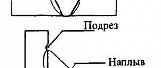
- undercuts _ Grooves are formed along the connection line or near it, leading to rapid destruction of the structure;
- pores _ Visually, they are practically invisible; they arise due to the penetration of gases formed during the melting of the electrode and metal;
- lack of penetration . Areas where the metal has not melted sufficiently, resulting in gaps at the weld joint;
- third party inclusions . One of the most dangerous mistakes, as a result of which the strength of the connection is significantly reduced and cracks appear in it over time;
- cold and hot cracks . The first are formed after the structure cools due to oxidation during the melting process. The latter arise during the process of metal melting when welding technology is violated, for example, when the electrodes are incorrectly selected.
All these defects can be avoided if you first perform calculations using existing formulas. This will help create high-quality connections that can withstand critical loads and forces during operation of the structure.
Weld seam calculators
There are specialized calculators with which, without special skills, it is easy to calculate the length of the weld and determine the optimal parameters for corner, point and butt joints.
Using the calculator, you can check all existing typical joints with loads applied to them with different forces. Calculations will help you choose the size and type of butt joint that is suitable for a specific design, as well as accurately select the material for welding. Calculations make it possible to establish the required geometric values of the weld and test it for strength.
It is not recommended to apply fatigue loads to point joints, grooved joints and electric rivets, since the calculation of such welds is not supported and the results will be inaccurate. Also, the calculations do not take into account changes in the mechanical characteristics of metals that arise due to the effects of residual stresses and temperature conditions.
Fatigue strength of welded joints
Fatigue (vibration) strength depends, as is known, on many factors: on the operating stresses and cycle characteristics, on the scale factor, the properties of the material and the state of its surface.
The influence of these factors is widely known and is not discussed here. However, we note that the welded joint has one feature that significantly affects the vibration strength of the joint: the presence of stress concentration at the point of transition of the weld metal to the base metal. In the laboratory of LCI welding using the photoelastic method, the values of theoretical stress concentration coefficients were established for samples simulating welded joints with different seam shapes. Stress concentration coefficients vary within significant limits, and the shape of the seam (in this sense) plays a significant role. The actual stress concentration factors, which are called effective concentration factors (Kf), depend not only on the shape of the weld, but also on the sensitivity of the metal to the notch. If you know the value of the fatigue limit of a smooth sample and the effective concentration coefficient for various types of welded joints, you can, without testing, establish the value of the fatigue limit of a given connection using the formula of B. N. Duchinsky. The fatigue limit of welded joints should be compared not with the fatigue limit of a smooth sample, but with the fatigue limit of a sample with a rivet joint, since if welding is abandoned, the ship’s hull can only be built using riveting. The fatigue limit of welded joints will always be higher than that of corresponding riveted joints.
The second reason why in ship structures it is not necessary to increase the fatigue strength of welded joints by special measures (mechanical processing) is that the ship hull does not experience the correct alternating long-term and regular loads that exist during fatigue tests. The exceptions are hull structures in the area of propellers, machine foundations and structures in the area of installation of unbalanced mechanisms, etc. For these areas, the reduced fatigue strength of welded joints is taken into account in the calculation by the fact that not the yield strength, but the fatigue limit and the permissible stresses are taken as a certain part of the fatigue limit.
See also:
The influence of residual welding stresses and deformations on the static and fatigue strength of welded structures
The influence of low temperatures on the strength of welded joints
Corrosion resistance of welded joints
Welding methods
Mechanization of gas cutting operations
Destruction of welded ship structures and their analysis
Tools for checking weld dimensions
The geometric parameters of welding joints are determined using special tools that make it possible, with minimal errors, to measure the main indicators and characteristics produced by the technology of welding structures.
These tools include standard templates, universal devices and meters, the principle of which is to measure one specific parameter.
Every professional welder must have a set of measuring instruments available for taking measurements for preliminary calculations before the welding process, as well as determining the quality of the weld of the finished structure.