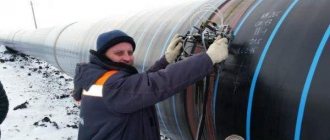
When constructing power plants, petrochemical plants, gas pipelines and other facilities with welded pipeline joints, standards require the preparation of working documentation. This is done for comprehensive control over the quality of work and the compliance of the constructed facility with design requirements.
An important tool for such control is the diagram of welded joints. It shows a schematic view of the facility’s pipelines, equipment, shut-off and control valves and connecting welds. Next to each connection is information related to it.
What it is?
The as-built diagram is an integral element of the design and working documentation of water supply, heat supply, transport pipelines and technological installations with liquid or gaseous media. It is not to scale and gives only a general idea of the relative position of the welds in space. The drawing is necessarily linked to geodetic coordinates or to an object with known coordinates.
When forming a document, the order of the seams on a particular section of the pipeline is observed. The document is a guide to welding work, a planning and control tool. It is issued together with a summary table of joints, summarizing the data on joints in tabular form. In addition to the technical parameters of the seams, personal data of the welders and the number of their personal mark are given.
Decor
The document is drawn up by the organization conducting the installation work . It is compiled by the production and technical department on the basis of design and working documentation transferred to installers from the customer or directly from the designer, if provided for by the contract.
Based on the 3D model of the object presented by the designer, the technical department begins the formation of a weld pattern.
Simultaneously with drawing up the scheme, other related documents are also prepared:
- summary table of joints;
- acts of welders performing test welds and assigning them a personal mark;
- certificates of welding work.
Without a complete set of documents, the facility cannot be accepted for operation
Signature
The layout of the welded joints of the pipeline must be certified by the signatures of the following officials:
- foreman directly responsible for performing welding work at the site;
- head of production and technical department;
- Chief Engineer;
- welders who performed the work, indicating the number of their personal mark.
The completed and certified document must be agreed upon with the design organization.
It is also necessary to coordinate with it all deviations from design parameters encountered as a result of monitoring, such as dimensions and slopes. A certified record of the absence of deviations or their agreement is made on the form. If there are many deviations, they can be agreed upon in a separate act. Then the document contains a link to the number and date of this document
Pivot table
The document is drawn up according to the unified form P27.4, approved by Order of the Ministry of Energy No. 197. It must contain a complete list of seams welded at the facility.
The pivot table contains information about all connections of an object in a form convenient for control, generalization and analysis.
The following data is provided for each connection:
- serial number,
- the name of the node to which it belongs;
- type of steel alloy from which the pipes are made;
- their diameter and wall thickness;
- quantity;
- number corresponding to the designation on the Diagram.
If additional seams were welded on the site, their number and number are given in the additions column . This table allows you to determine the total number of joints, group them by diameter, wall thickness, and the need for non-destructive testing. This makes it easier to plan labor intensity, the need for consumables, as well as instrumental quality control of connections.
Designation (numbering) scheme for welded joints. Is it obligatory?
In addition to the technical parameters of the seams, personal data of the welders and the number of their personal mark are given. The document is drawn up by the organization conducting the installation work. It is compiled by the production and technical department on the basis of design and working documentation transferred to installers from the customer or directly from the designer, if provided for by the contract.
Based on the 3D model of the object presented by the designer, the technical department begins the formation of a weld pattern. The layout of the welded joints of the pipeline must be certified by the signatures of the following officials:. It is also necessary to coordinate with it all deviations from design parameters encountered as a result of monitoring, such as dimensions and slopes.
A certified record of the absence of deviations or their agreement is made on the form. If there are many deviations, they can be agreed upon in a separate act.
Then the document contains a link to the number and date of this document. The document is drawn up according to the unified form P. It must contain a complete list of seams welded at the site. The pivot table contains information about all connections of an object in a form convenient for control, generalization and analysis. If additional seams were welded at the site, their number and number are given in the additions column.
This table allows you to determine the total number of joints, group them by diameter, wall thickness, and the need for non-destructive testing. This makes it easier to plan labor intensity, the need for consumables, as well as instrumental quality control of connections.
Each joint on the diagram must have its own unique number. The stage of forming a diagram of welded joints from a 3D model. The drawing is simplified, fittings and equipment are replaced with symbols. In addition, the diagram can indicate the distance between adjacent joints and supporting objects, such as turns, reinforcement, supporting metal structures or process equipment.
This is mandatory in two cases:. Designations, if necessary, for example, in the event of an accident, planned repairs or inspection, will help you quickly and without unnecessary costs and damage to structures to find the junction in the event of repairs, without resorting to additional documentation. Mechanical tests. Metallographic research. Number and date of the protocol.
Layout diagram of welded joints of pipelines example. Distance between joints. Steel grade, heat number and pipe number. Installation repair organization. Last name, initials.
Schemes for buildings and structures, landscaping and geodetic alignment basis
Chief Engineer. Directorate representative. Installation and repair foreman. Head of welding works. Node name. Connected pipes. Data on welding installation repair joints according to working drawings.
Design rules
The pipeline welding diagram must contain the following information:
- Object name;
- pipeline class;
- pipe parameters: alloy material, diameter and wall thickness;
- transportable medium;
- snapping to reference points.
Each joint on the diagram must have its own unique number . Sometimes continuous numbering of welded joints throughout the entire project is used, then the designation takes the form “E12.123”, where before the dot there is an object identifier, and after the actual joint number on a specific diagram.
The stage of forming a diagram of welded joints from a 3D model. The drawing is simplified, fittings and equipment are replaced with symbols.
In addition, the diagram can indicate the distance between adjacent joints and supporting objects, such as turns, reinforcement, supporting metal structures or process equipment. This is mandatory in two cases:
- the pipeline is covered with a layer of insulation;
- the site runs underground or is hidden in the walls.
If necessary, markings (for example, in the event of an accident, planned repair or inspection) will help you quickly and without unnecessary costs and damage to structures find the joint in the event of repairs, without resorting to additional documentation.
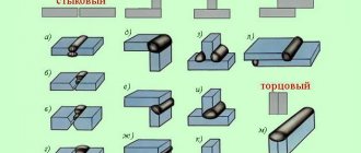
Joints in a schematic drawing can be of two types:
- rotary;
- non-rotating.
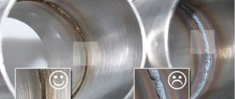
Rotary welds include welds made by a welder with a section of pipe rotated along the longitudinal axis at a certain angle . Usually this is an angle that is a multiple of 90°. Such seams are welded in the “bottom” position. Such seams are of higher quality and more durable, since the work is carried out in a position convenient for welding. Analysis of statistical data shows that the frequency of detection of defects in such seams is significantly lower than in non-rotating ones. welded joints.
A fixed joint is welded without rotating the pipe to a convenient position . On the contrary, the welder has to follow the seam around the pipeline, including in disadvantageous positions: seams with a positive and negative slope, as well as vertical and ceiling ones. In this case, it is necessary to change the inclination of the electrode, its speed, welding current and other important operating modes several times.
In this case, the seam is welded in several stages, which negatively affects its strength and durability. Working in such conditions requires a worker with extensive experience and high qualifications.
Near each joint, the details of the welders who welded it are indicated (full name, personnel number or personal mark number).
The document also notes connections for which quality control will be required by non-destructive means (ultrasound, x-ray, etc.). For particularly important objects associated with high pressures and temperatures, aggressive environments and other factors, control is carried out for all joints.
The location diagram of welded joints indicates the joints at which non-destructive testing (ultrasonic, radiographic) is required. All joints are subject to visual inspection.
When drawing up a document, the same coordinate system is used as in other design and working documentation.
Important! The schema data and the summary table must match the Work Log data in the following parameters:
- connection numbers;
- pipe parameters;
- Full name of welders and personal mark numbers
- duration of work.
If the dimensions and slopes of the constructed object correspond to the design values, the inscription is written on the diagram: “There are no deviations from the design parameters.” Otherwise, a designer's inscription coordinating these deviations or a link to a separate document - an act of approval - is required.
The diagram is included in the object passport , drawn up on high-quality media and using materials that guarantee long-term storage.
After completion of the work, all documentation is checked for completeness and correctness of execution and filling. After verification, the documents are handed over to the archive.
Technical center "WELDING"
The layout of welded joints is not to scale. Welded joints should be marked on the diagram. The distance between joints is indicated if the pipeline is subsequently insulated or underground. This is necessary to determine the location of the welded joint.
The joints in the diagram are indicated as rotary and non-rotary.
A rotary joint is a pipeline joint that is welded by rotating the pipe by 360˚, 180˚ or 90˚, and welding is usually performed in the lower position.
A rotary joint is easier to perform, since welding occurs in a comfortable position, which in turn indirectly affects the quality of welding. The likelihood of defects occurring is much less than when welding non-rotary joints.
A fixed joint is a pipeline joint, welding of which occurs without rotating the pipe, and the welder himself performs welding in various positions around the pipeline.
A fixed joint is difficult to make. The main difficulty lies in the need to weld in different positions (bottom, vertical, ceiling seam). When welding in different positions, it is necessary to adjust the current strength. Welding a fixed joint requires high skill.
Before approval at the site, the welder must weld test and approval joints. The dimensions, design and position of the trial and acceptance joints must match the standard dimensions of production welded joints.
Also on the diagram of welded joints the number of the joint is indicated. The numerator indicates the serial number of the joint. The denominator indicates the personal mark of the welder.
The welder's mark is assigned upon passing certification at the NAKS certification center. To work at hazardous production facilities, the welder’s mark is assigned by order of the enterprise , in accordance with clause 8 of the Federal Tax Code.
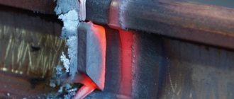
The welder's mark is made in accordance with GOST 25726-83. On one side of the brand there is a mirrored alphabetic and numerical designation, on the other side there is a place for impact during branding.
Depending on the object on which welding is being carried out, the mark is located at a distance of 40mm - 60mm from the welded joint. When welding is performed by several welders, marks are placed at the boundaries of the joints.
Marking of welded joints is necessary to identify the welder who made the welded joint. If defects are detected in the welded joint, the contractor is determined by the applied mark and the issue of removing the welder from work and recertifying him, with passing practical and theoretical exams, is decided.
The diagram of the location of welded joints indicates the joints at which non-destructive testing (ultrasonic, radiographic) was performed. All joints are subject to visual inspection. For each hazardous production facility, the scope of control is determined according to the relevant regulatory documents.
A summary table of welded joints, carried out on the diagram, will allow you to determine the number of joints of different diameters and the required number of non-destructive testing.
The stamp for the location of welded joints is signed by the welding supervisor, the welders who performed the welding, and the installation supervisor.
The location diagram of welded joints indicates the name of the object, the group or class of the pipeline, the diameter and thickness of the pipeline wall, the working environment, connections to fixed supports, buildings, fittings, etc.
Important!!! The layout of welded joints must correspond to the welding work log. (Numbering of joints, marks, diameters, wall thickness, welding sequence, as well as welders).
Designations of joints in the diagram
The joints in the diagram are indicated in accordance with the state standard GOST 2.312-72 “Conventional images and designations of seams of welded joints”, with a solid main line.
The following inscription is made in the form of a fraction on the take-out:
- numerator - joint number;
- denominator is the number of the welder’s personal mark.
A personal mark is issued for each welder separately . During certification, he welds a test seam that matches the material, diameter and thickness of the pipes with the actual connections on site. Such tests are carried out in special certification centers, the number of the personal mark is approved by order of the installation company.
Requires an as-built diagram for welded joints
Data on additionally welded joints. Installation organization. Installation foreman. This form is based on. Full Name. Number and validity period of the certificate.
In terms of welding and technological properties, in accordance with the requirements of GOST, the electrodes are recognized as suitable for welding critical products.
Go to new. Is it obligatory? Hello, sometimes you will have to attach acts of VIC, UZK, capillary control, and so on to the as-built documentation. The customer began to demand, number the joints, and make a designation diagram for welded joints.
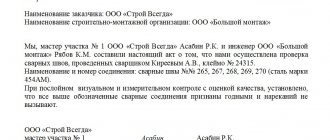
The steeloscopy results showed the following:. As a result of visual inspection and measurement it was established:.
The remaining joints were found to be suitable according to the results of visual inspection. After eliminating the defects, these joints must be checked again and a repeat report must be drawn up. Pipeline or assembly.
What you will receive:
Diameter and wall thickness, mm. Steel grade. The type of joint is control or production. Type of welding.
When constructing power plants, petrochemical plants, gas pipelines and other facilities with welded pipeline joints, standards require the preparation of working documentation. This is done for comprehensive control over the quality of work and the compliance of the constructed facility with design requirements.
Brand of filler material. Thermal treatment mode. Type of test. Number of samples.
Sample marking. Last name, initials of the welder. Laboratory stamp.
Pipeline, unit. Sample marking. View profile. Message 1. Dear specialists, a question has arisen: I need to make a welding diagram for the internal gas pipelines of the boiler room for execution, I have never done this. If anyone has one, please share it as an example. Thank you in advance. Message 2. For this, an axonometric diagram of the gas pipeline is used, which indicates the locations of all welds, the lengths of straight sections, bends, tees, etc.
Construction catalog
Message 3. Message 4.
What a horror All joints must be numbered, the welder's mark must be affixed, in the areas between the seams it must be signed which pipe the GOST pipeline is made of, the length of the section, diameter and wall thickness. Well, in the notes the result is how many seams of what diameter in total. Message 5. Message 6. I do this: on the axonometric diagram of the internal gas pipeline in the project, I show the locations of only the transilluminated joints, a rotary or non-rotary joint, the number of the joint and the number of the welder’s mark.
There were no problems during 3 years of operation. But it’s correct to do it according to the scheme above OST Message edited by astronom55 - 6. Message 7. Good afternoon everyone.
Sample form
All forms are filled out in accordance with the requirements of the standard. Below is a welding form for the pipeline (sample) .
The document is at the final stage of formation. Contains the necessary joint data, corner stamp and additional information. A summary table is visible above the stamp.
The diagram of welded joints is an important document that describes the relative position of the joints and their most important parameters . It is issued for any facility that has pipelines with welded seams. The diagram and the summary table compiled with it serve as a means of planning installation work, recording execution and quality control.
Gas pipeline welding technology
When welding any type of gas pipeline, a technological map , which indicates:
- main materials of welded parts
- type of welding
- equipment used
- equipment parameters
- temperature regime
- safety regulations
- methods for monitoring the received connection
The process of welding gas pipelines is one of the main stages of installation, because The reliability of the entire structure depends on it.
Requirements for welding gas pipelines are specified in RD 01-001-06, STO Gazprom 2-2.2-136-2007
The welded joint must be equal in strength to the base metal of the pipes or have a strength coefficient guaranteed by the manufacturer (according to GOST or TU).
Welding is used for gas pipelines of all pressures:
- high
- average
- low
- main
For each category, high reliability of connection units, adherence to technology for performing all operations and serious quality control are important.
Welding of main gas pipelines
There are certain difficulties when welding gas pipelines, where the pressure reaches 10 MPa:
- the welding seam of the gas pipeline is exposed to very high pressure from the inside;
- due to a decrease in soil temperature during the cold season, the metal is deformed and additional stresses arise in the seams,
- during installation and insulation work, the seams are subjected to significant bending stresses;
In this regard, the welding connection of main gas pipelines is considered the most demanding in terms of the quality of equipment, personnel and materials.
The design dimensions of the edges when connecting pipes and parts of the same outer diameter with different wall thicknesses must comply with the requirements of SP 86.13330.2011
.
Technological features when welding gas pipelines of any pressure
The types, structural elements and dimensions of connections of steel gas pipelines must comply with GOST 16037-80. For underground gas pipelines, only butt and corner connections should be used.
The use of welding materials is permitted only if there are certificates from manufacturers or copies thereof.
Before use, welding materials should be checked by external inspection for their compliance with the requirements of GOST (TU). If defects are detected, the use of these materials is not permitted.
Control of the permissible joint should be carried out by external inspection for compliance with the requirements of GOST 16037-80
Before assembling steel pipes for welding, you must:
- Clean their internal cavity from possible blockages (soil, ice, construction debris, water, etc.)
- Check the geometric dimensions of the cutting edges, straighten smooth dents at the ends of the pipes with a depth of up to 3.5% of the outer diameter of the pipe;
- Clean the edges and adjacent internal and external surfaces of the pipes to a width of at least 10 mm to bare metal;
The ends of pipes that have cracks, tears, nicks, or chamfers with a depth of more than 5 mm should be cut off. At air temperatures below minus 5 °C, straightening the ends of pipes without heating them is not allowed.
When welding an internal gas pipeline, inserting branches with a diameter of up to 50 mm, the distance from the seams of the welded fittings to the circumferential seams of the main gas pipeline must be at least 50 mm
Welding work outdoors during rain, snowfall, fog and wind speeds of 10 m/s can only be carried out if the welding site is protected from moisture and wind.