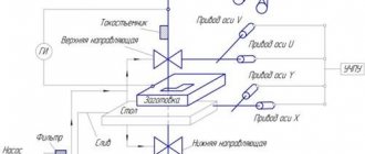
Shaping scheme [edit | edit code ]
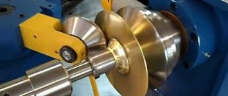
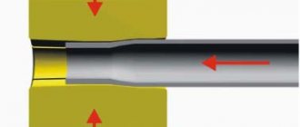
The RV is produced from a workpiece mounted on a rotating mandrel by rollers, satellite-rotating from the workpiece, which move along the generatrix of the mandrel with the required specified clearance. When the rollers come into contact with the workpiece, a large specific pressure arises at the point of contact, under the influence of which the metal of the workpiece plastically flows into the gap between the roller and the mandrel, forming a part. The inner surface of the part takes the shape of the outer surface of the mandrel, and the outer contour of the part follows the trajectory of movement of the working edge of the roller.
On modern rotary drawing mills, rolling can be carried out with one, two or three rollers. The presence of tensile forces in the molded area of the workpiece during the entire drawing process and the fact that the molded part of the workpiece is always on the mandrel reduces the possibility of longitudinal bending of the part even in the presence of slight runout of the mandrel or slight variation in the thickness of the workpiece.
Shaping methods [edit | edit code ]
There are two main methods of Rotary hood:
- Direct, in which the direction of material flow coincides with the direction of movement of the roller;
- Reverse, in which the direction of material flow is opposite to the direction of movement of the roller.
In direct rotary drawing, the outer contour of the mandrel must follow the inner contour of the drawn part with technological allowances, so the length of the mandrel must be greater than the length of the part, which complicates the design of the mandrel, makes it heavy and expensive, and makes adjustment more labor-intensive.
The direct method of rotary drawing is recommended for shaping thin-walled and long cylindrical parts, as well as all types of parts of conical and ogive shapes. When using the reverse method, the mandrel must correspond to the internal contour of the workpiece, so the mandrel can be several times shorter than the part. However, with this method there is a danger of longitudinal bending of the extruded part after it leaves the mandrel, which imposes particularly stringent requirements on the thickness difference of the workpiece, runout of the mandrel and rollers, and on the accuracy of setting the gap between the mandrel and all rollers.
The reverse method can be used for shaping relatively thick-walled and short precision blanks of cylindrical parts or blanks of parts.
The rotary drawing process can be divided into processing without thinning, with thinning and sheeting.
When extruding without thinning over several successive passes of the tool, the wall thickness does not change or decreases slightly. A more or less significant reduction in the maximum diameter of the workpiece is obtained when processing without thinning. When processing with thinning and rolling, the outer diameter of the workpiece (or inner diameter of the pipes) and the resulting part remains unchanged, and the wall thickness is more or less significantly reduced; due to this, the length of the resulting part along the axis of rotation increases. With rotary drawing, the workpiece is installed between a mandrel mounted on the spindle and the tailstock clamp.
Parts processed on pressing and rolling machines and machines [edit | edit code ]
The rotary drawing process was at one time used to a limited extent to produce parts such as bodies of rotation with a conical or cylindrical generatrix; Now this method is often used to produce parts with a curved forming surface when the roller moves using a CNC-controlled hydraulic support. The parts are edging, molded with special rollers, and annular grooves and ribs are extruded.
Many parts that were previously produced by cutting from bar material, forgings and stampings, and with a constant wall thickness by deep drawing, are successfully processed on rotary machines and lathes.
When processing preheated workpieces, the diameters of the parts reach up to 7 m, and the thickness of the workpieces reaches 30 mm and above.
Read also: The meshing pitch of a gear is
The material of parts manufactured for rotary drawing on machines from sheet and pre-processed hollow workpieces such as bodies of revolution can be low-carbon steel, aluminum, copper, brass, and heat-resistant alloys.
Aluminum and its alloys are the most easily machined materials on pressing machines, but mild steel designed for deep drawing can be processed well. Usually, high-quality pure metal without slag and foreign inclusions is used. Otherwise, cracks will form in the metal during rotary drawing, and the products will be rejected.
Many ferrous and non-ferrous metals are suitable for rotary drawing. The metal used for this usually must have low resistance to deformation, high ductility, and low yield strength.
Some alloy parts are difficult to machine, but can be easily machined on rotary drawing machines.
When transferring parts to rotary drawing and when designing new products designed for production by this method, the possibility of its use is analyzed, taking into account the economic advantages over other manufacturing methods. The greatest benefit and efficiency can be achieved if new machines are designed with rotary drafting in mind.
Scope of application of products [ edit | edit code ]
According to foreign data, the widest area of application of crush-rolling processing is the production of parts for jet engines and guided missiles, as well as the bottoms of radar screen tanks, searchlight housings, and lamp screens.
For example, this method is used to produce:
- The conical part of the exhaust pipes is made of 3 mm thick sheet steel; the finished part has a cone angle of 34°, the diameter of the base of the part is 500 mm, height is 640 mm, wall thickness is 1 mm;
- Nozzles (nozzles) made from stainless steel blanks, conical in shape, 127 mm long, processed on lathe-type machines. After rotary drawing, the nozzle has the following dimensions: height 305 mm, wall thickness 1.14 mm, part cone angle 12°;
- Bearing housing (ring). The workpiece is a machined forging of alloy chromium steel. The largest diameter of the finished part is 508 mm, the cone angle is 84°, the wall thickness along the cone is from 3.2 to 2.3 mm;
- Compressor rear casing. Welded blank made of stainless steel sheet. After rotary drawing, a hollow cylindrical part with an internal diameter of 710 mm and a length of 197 mm is obtained. The part is then machined internally and externally to achieve a wall thickness of 6.4mm. The operations of edging, turning and pressing-rolling produce five internal ribs and a wall thickness of 1.5 mm while increasing the length of the part to 380 mm. At the end of processing, the operation of applying corrugations is performed using specially shaped rollers.
Rotary drawing can easily produce massive tubular parts with variable thickness of machined wall ends and external annular ribs. In combination with rotary drawing, additional operations can be used to obtain complex shapes of parts: rolling, stamping, welding. Rotary drawing can also be used as an auxiliary tool for giving the final shape to the workpieces obtained by drawing. Often, pressing machines process individual sections (parts) of parts assembled by welding or riveting. This makes it possible to produce tubular parts with different combinations of sections.
It is effective to rotary draw long copper conical parts used in some industries. It is difficult to produce such parts on presses, if, in addition, there are strict requirements for the quality of their surface.
A rotary hood is also useful for making household utensils and similar thin-walled products of complex shape: ladles, cups, cans, teapots, coffee pots, cylinders, kettles, barrels, round parts of fans and exhaust hoods, shaped copper parts of brewing installations, concrete mixer drums, large vessels and utensils products for the chemical and food industries.
Classification of CNC machine tools
Pressure-rotary drawing has many of the properties and functions of turning analogues. In contrast, pressure-rotary devices have a higher operating speed. There are three types of devices of this type:
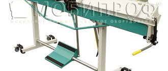
- manual tabletop;
- manual floor;
- with a rotary hood.
Rotary drawing is accompanied by additional actions such as rolling, expanding and welding. The rolling machine is capable of both producing a solid part using the rolling method, and completing the drawing and production of spare parts made using other equipment. The most popular products of this kind, for example, are tubular spare parts with various combinations of cross-sections.
The machines can be used not only for processing metal parts, but also copper ones that have a conical shape. The advantage of CNC devices is that the process is less labor-intensive than using presses. Modern technologies make it possible to monitor the operation of devices remotely. Round metal plates are used as the main raw material for working on a rotary pressing machine.
But the devices can also cope with workpieces that have a more complex geometric shape. Additional methods of working with the product are circular and hydrojet cutting. Examples of plasma and laser cutting in this case are less effective, since they can increase the temperature, which will change the plastic qualities of the spare part.
Tool used [ edit | edit code ]
Rollers are used as a tool for working with rotary drawing. The rollers, installed on special machine tools, rotate on the shaft in bearings in contact with the workpiece material of the rotating workpieces.
A device for installing a roller on a machine is a rigid device that is installed, fixed and securely fastened after alignment on the machine slide. It must correspond to the rigidity of the pressing machine and withstand, without large deformations, significant forces arising during operation, ensuring stable operation of the pressing and rolling machine.
The rollers are made from high-quality tool (high-speed) steel such as HVG, U10, U8, heat-treated (hardening, tempering) to a hardness of HRC 62-64. During pressing and rolling processing a significant amount of heat is generated. Although some heat is dissipated by the coolant, the rollers must be resistant to elevated temperatures.
The shafts for installing and securing the rollers are made solid, and for very large sizes, welded from tool steel. The working surfaces of the rollers after installation on the shaft should not have any runout. Changing the roller on the device should not take much time. After landing on the shaft, the rollers should absorb axial and radial forces without deformation or displacement. The rollers on the shaft bearings rotate easily under load. When starting the pressing process, the rotation of the roller must be recorded. At the slightest jamming of rotation, pulsating forces and vibrations arise, which leads to irremovable defects of the processed surface - corrugations.
Read also: Laser cutting equipment
For various pressing and rolling operations, rollers of various shapes are used, taking into account the profile of the resulting parts. The working surface of the rollers is ground and polished to a mirror finish, avoiding surface defects. Rollers for heavy work have diameters of 250-300 mm, the radius of curvature of the working part is 6-20 mm. A curvature radius of 3-6 mm is used for processing material with a thickness of less than 4 mm. There are no substantiated recommendations on the choice of roller radius values for pressing work yet. The radius of curvature of the roller affects the deformation force and stability of the workpiece during processing. With increasing radius, a material of small thickness not only loses stability, but also greatly stretches, even to the point of rupture. When the roller radius of curvature decreases, the workpiece flange is cut.
Mandrels-cartridges [edit | edit code ]
As a device (mandrel, chuck) for pressing and rolling work, mandrels are used, installed and secured in the spindle of the machine. For large-scale and mass production, they are made from case-hardened low-carbon steel. The working surface of the mandrels is ground; It is recommended to carry out final grinding on site to eliminate the slightest runout.
When manufacturing precision parts to obtain dimensions with tight tolerances, the last processing operation must be performed on a metal mandrel. For rough work, hardwood mandrels can be used.
The accuracy of parts after pressing and rolling processing depends on the runout of the machine spindle, the runout and degree of wear of the mandrel, the rigidity and accuracy of the machine, the quality of the workpiece material, the method of removing the part from the mandrel and other factors.
The cost of a tool for pressing and rolling processing is not high and is usually 10-25% of the cost of a tool used in plastic forming performed by other methods.
| 89636543965 |
Is the product in the wrong category?
Click on the link and we will select the correct category for the product.
designed for the production of rotationally symmetrical hollow surfaces from round metal blanks with a thickness of 0.2 - 3 mm, by processing them with a pressure hand tool without removing the material, by deforming and stretching it when rotating the blank with an emphasis on the template part.
Specifications
| Maximum workpiece diameter, mm | 1200 |
| Maximum length of the finished part, mm | 460 |
| Workpiece rotation speed, rpm | 2800/1440/720 rpm |
| Metal thickness, mm |
Steel – up to 1.2 – 2 mm (depending on the D of the product)
Stainless steel – up to 1.5 mm
Aluminum (5mm), copper, tin – up to 4 mm
Equipment:
bed, spindle headstock, main spindle drive – 3-phase (380V) asynchronous electric motor with a power of 5.5 kW, tailstock with double V-belt pulley with two pairs of pulleys for adjusting the rotation speed (by rearranging the belts on the second pair of pulleys), clamping device workpieces (optimized with a bolt mechanism for quick removal of the finished product), persistent cradle for hand tools. The maximum diameter of the workpiece being processed is 1200mm. Approximate assembled weight 1200 kg.
Rotary drawing is a widespread method of metal processing; it is used for the production of thin-walled hollow parts in the form of bodies of rotation.
It is carried out by applying pressure to a rotating sheet or hollow workpiece, resulting in the shape of a mandrel.
Main advantages of RV technology
Traditional metal processing technologies such as forging, casting or stamping do not have the advantages that RV has. In the process of processing parts using RV technology, significant savings in time and money can be achieved. The advantages of RT technology usually include:
- Automated RV machines have high productivity, especially when it comes to the operation of forming cones.
- The part completely follows the profile and requires almost no additional processing.
- Even the production of small or pilot series of parts proves the maximum economic efficiency of RV technology.
- RV technology can significantly reduce the production cycle.
- RV technology makes it possible to significantly speed up the process of manufacturing any batches of parts of the most complex shape; traditional metal processing methods such as forging or casting are inferior in many respects.
- When manufacturing parts, material consumption is significantly reduced.
- The technology makes it possible to produce parts from blanks with a thickness close to the thickness of the part walls.
- Devices and tools have low cost, increased strength and low weight.
- The equipment and tools used in the manufacture of parts using RV technology are more cost-effective in comparison with the tools and equipment used in traditional metal processing.
- There is no need to produce stamps and injection molding models, which typically require the use of expensive materials and manual labor.
- Parts after manufacturing using RV technology have increased strength and a homogeneous structure.
- Thanks to this, it is possible to significantly increase the service life of not only the part, but also the assembly unit as a whole.
- The equipment can be quickly reconfigured to produce another part. One workplace allows you to perform several operations, thanks to which the full processing cycle is significantly reduced.
- There is no need to use a large amount of equipment and special equipment for each technological transition.
Quite low cost of the preparatory cycle for manufacturing a part. If production is pilot or small-scale, then its economic efficiency is maximum.
Metal drawing and its types
Main types of rotary metal drawing:
Step molding
A sheet blank in the shape of a circle is fixed between the mandrel and the support. The mandrel must match the internal configuration of the product. The drive begins to rotate the blank, and controlled forming pressure is carried out by a special passive roller driven by the rotation of the blank. Pressure is applied in both longitudinal and radial planes. The roller presses the metal against the mandrel and moves along a complex curve, either towards the edge of the blank or back.
The clamping is carried out in several passes, in steps. At the end of the treatment, a series of smoothing movements of the roller are carried out with reduced pressure to obtain a high-quality surface.
Projection - One-Pass Molding
Extraction is carried out in one pass. The roller moves parallel to the mandrel, depending on the angle of its installation, the wall of the blank is thinned more or less, its material moves under the influence of the roller in the axial direction.
Projection - One-Pass Molding
The method is characterized by efficiency and dimensional accuracy, as well as a high class of the resulting surface.
Rolling with or without mandrel
In this case, the outer diameter of the workpiece is reduced with a simultaneous thickening of its wall due to the redistribution of the material. Rolling is carried out towards the center, in several passes.
Read also: Connect the connector to the network cable
Rolling with or without mandrel
As an option, the part is formed by individual segments of the mandrel using a roller with an offset center. Cutting, additional profiling or flanging are carried out as final operations.
Combined
For parts with complex configurations, stepwise forming, rolling, profiling and cutting are used together in various combinations.
Sheet Metal Pulling
Drawing is the process of transforming a flat workpiece into a cavity part of any shape (or further changing its dimensions) and is carried out using dies. In Fig. Figure 8.17 shows a diagram of drawing a cylindrical part from a flat workpiece. The latter is characterized by a decrease in the outer diameter of the flange and movement of the workpiece elements (1-5) as the extraction depth increases.
When stretched, the annular part of the workpiece (D - d) turns into a cylinder with diameter d and height h. Due to the fact that the volume of the metal does not change during this process, when the cylinder is fully extended, the height of the part h will be greater than the width of the annular part b and will be:
- (8.22)
where K = D/d is the degree of drawing.
At K = 2, h = 1.5b. Consequently, drawing occurs due to plastic deformation, which is accompanied by a displacement of a significant volume of metal in height. With a large degree of deformation, corresponding to deep drawing, and with an insignificant thickness of the material, the displaced volume causes the formation of corrugations (waves) on the deformed workpiece. At a low degree of deformation and at a relatively greater thickness of the material, corrugation does not occur, since in this case the displaced volume of metal is small and the workpiece is resistant.
To prevent the formation of corrugations and folds during stretching, pressure is applied to the workpiece and the holder.
| Drawing. 8.17. The sequence of metal movement during the drawing process |
Using this process, a large number of cavity parts of a wide variety of shapes are manufactured, differing from each other both in plan outline and in the shape of the side walls.
According to their geometric shape, all cavity parts can be divided into three groups:
- 1) axisymmetric shape (body of rotation);
- 2) box-shaped;
- 3) complex asymmetrical shape.
Each group is divided into several varieties. For example, bodies of revolution can be cylindrical, conical, curved, stepped, convex-concave in shape. The construction of the technological process and technological calculations are different for them.
It has been established that the process of deep pulling from pressing begins not with plastic deformation of the workpiece flange, but with the initial stage of the process preceding it, which consists of local plastic deformation of the annular, non-clamped part of the workpiece.
| Drawing. 8.18. The sequence of the deep drawing process with pressing the workpiece. |
In Fig. 8.18 shows the sequence of the process of pressing the workpiece; the upper diagrams 1 show the initial stage of the process, which consists of local plastic deformation of the free annular section a, with a clamped flange that retains its original dimensions dФ = Do. This stretching stage is carried out by stretching and thinning the annular section, with the greatest thinning occurring at the boundary of this section with a flat bottom.
As the punch sinks, the pulling force increases, and the stretching and thinning of the free section of the workpiece increases. Towards the end of this stage, plastic deformation of the bottom part of the workpiece occurs. After achieving equilibrium between the pulling force and the flange's resistance to deformation, the second stage of the process begins, which consists of plastic deformation of the flange and retraction of it into the matrix (see diagram II in Fig. 8.18). Thus, the process of deep drawing with clamping consists of two technologically different stages:
- primary
- final.
When pulling with a clamp with a low degree of deformation, the initial stage is practically absent.
| Drawing. 8.19. Deformation of the flange element (a) and pattern of corrugation formation (b) during pulling |
In the initial stage of the deep drawing process, a significant thinning of the free section occurs, which in the process of further deformation turns into a dangerous section. In the second stage of stretching, complex plastic deformation takes place, during which the element of the flat workpiece I (Fig. 8.19, a) changes its dimensions (Lengthens in the radial direction and shortens in the tangential direction) and takes position 11, and then undergoes bending and turns into an element lateral surface of the cavity product.
The plasticity condition of a deformable flange, which determines the moment of its transition to the plastic state, is expressed by the equation (taking into account the signs of stresses) σr + σt = 1.15 σr.
First, for workpiece element I, which is located near the outer edge of the flange (Fig. 8.19, a), the greatest is the tangential compression deformation, the average is the elongation deformation in the radial direction, and the least is the thickening of the metal.
As a result of tangential compression deformation when pulling thin material, the flange easily loses stability, due to which corrugations form on it. In thick material, with the same dimensions of the workpiece and product, the occurrence of corrugations is difficult due to the greater stability of the workpiece flange.
When the element moves to the exhaust rib of the matrix, the radial elongation deformation becomes greatest, since the tangential compression gradually decreases. When an element passes through the exhaust rib of the matrix, this element deformation is complicated by the appearance of additional spatial bending deformation. After this, the workpiece element transforms into a curved-vertical wall and receives a slight axial elongation along the generatrix as the material becomes thinner.
The bottom of the products undergoes a slight flat elongation (1-3%) and thinning (2-5%), which in most cases cannot be neglected.
The experiments performed show that the deformation of the cylindrical walls in the gap and at the bottom rounding continues throughout the entire working stroke, and is accompanied by a continuous decrease in the thickness of the material.
Under the influence of tangential compression stresses, the workpiece flange loses stability and wavy corrugations form (l1, stage I). As a result of the impact component of the load on the workpiece, the resulting corrugation elastically deforms with the holder and its fastening and increases the gap between it and the matrix. The further effect of tangential compression is enhanced due to the continuous decrease in the outer diameter of the workpiece. This leads to flattening of the corrugated wave (stage 2), and then to loss of stability of the flat part of the corrugation, which bends in the opposite direction (stage 3). As a result, a smaller corrugation is formed, in which, instead of one, three full waves of length l2 arose (stage 4).
The process of corrugation continues in leaps and bounds until a completely stable small corrugation is formed. Depending on the different degrees of stability of the workpiece flange, characterized by the ratio S/d, as well as different degrees of deformation K = D/d, a different number of waves first appear around the circumference.
If the relative thickness of the workpiece is sufficiently large, corrugation does not occur because the flange does not lose stability during the pulling process.
The most dangerous place of the part is the transition zone from the bottom to the walls due to the occurrence here in the initial stage of drawing of significant thinning of the material and large tensile stresses.
With a large degree of deformation or in the case of the formation of folds on the workpiece, the tensile stress in a dangerous section exceeds its strength and leads to separation of the bottom. The strength condition of a dangerous section determines the possible degree of deformation and is expressed by the relationship:
- (8.23)
for steel 08 - 10 σmax ≤ 1.2 σв;
for steel 12X18H9 σmax ≤ 1.2 σв. Here σmax is the maximum stress in the dangerous section; σр is the actual tensile strength. The main direction of rational construction or improvement of the drawing process is to create the most favorable conditions for metal deformation, in order to reduce tensile stresses in a dangerous section:
- 1) reduction of stresses at the initial stage of the process;
- 2) reducing the resistance of a flat flange to deformation;
- 3) increasing the strength of the metal in the dangerous section;
- 4) reducing tangential compressive stresses in a deformable flange, or increasing its stability in order to prevent the formation of folds.
As a result of fulfilling the specified conditions, the following is achieved:
- increasing the extraction depth in one operation,
- reducing the number of operations,
- improving the process of drawing parts of complex shapes.
It must be pointed out that with different drawing methods, not all of the above conditions will be equally favorable.
From a technological point of view, drawing methods must be distinguished mainly by the type of stress state of the deformed part of the workpiece. The geometric shape of the part is a secondary feature in this regard.
Three main methods of pulling should be distinguished.
1) Drawing of cavity parts by converting a flat flange into a cylindrical or box-shaped shape, while creating a flat stressed state in the flange according to the compression-tension scheme (Fig. 8.18). This includes drawing cylindrical, oval, box-shaped and other parts with vertical or slightly inclined walls,
2) Drawing of spherical, curved and complex shapes of parts, in dies with drawing (braking) ribs. In this case, under the clamp, tensile stresses and deformations predominate, and in the other deformed part of the workpiece, a stressed state of bilateral tension arises.
3) Drawing with an elastic matrix and friction stretching, which create a collision of the workpiece, resulting in a reduction in tensile stresses in a deformation environment and facilitating the drawing process.
In the first method, the most favorable conditions for deformation consist in the maximum possible reduction in the resistance of the flat flange to deformation. This is achieved by:
- use of metal of reduced strength;
- annealing the workpiece;
- heating the flange;
- hood without pressure;
- effective lubrication.
As a result, tensile stresses in a dangerous section are reduced, the strength condition of this section is improved and deeper drawing becomes possible.
In the second method, a significant part of the workpiece is initially out of contact with the working parts of the die and easily forms corrugations and wrinkles. To prevent them, it is necessary to create increased radial tensile stresses and artificially increase the resistance of the deformed metal by dragging it through the exhaust (braking) ribs. At the same time, tensile stresses in a dangerous section increase significantly and the condition of its strength worsens. In order to create favorable conditions for deformation in this case and avoid rupture, it is necessary to ensure the strength condition of the dangerous section. This is only possible when using metal of increased strength and strengthening, with sufficiently high ductility (viscosity).
The third method has the most favorable deformation conditions, since in this case the strength of the dangerous section makes it possible to obtain a significant degree of deformation.
Therefore, for the drawing methods under consideration, it is necessary to select metal with different mechanical properties or in different states:
- in the first method - increased ductility with reduced strength (steel 08 - 10 in an annealed or normalized state with temper training);
- in the second method - increased strength with sufficiently high ductility and toughness (steel 08 - 10 after special treatment, stainless steel 12Х18H9T);
- in the third method, we use metal without increased mechanical properties.
In Fig. Figure 8.20 shows diagrams of the stress-strain state in various parts of the product during conventional drawing with clamping.
To visualize the nature of the deformation and the possibility of determining its magnitude in individual areas, the method of applying a rectangular or radial-ring coordinate grid to the workpiece is used, and then its distortion during stretching is studied. Mesh distortion measurements show that in the first operation, the tangential compression deformation exceeds the radial tension deformation.
| Drawing. 8.20. Diagrams of stress and strain during pulling (σ - stress; є - deformation; indices in σ and є mean: r - radial; t - tangential; s - axial). |
When drawing, the wall thickness of the parts changes. In the case of drawing cylindrical parts without a flange, the greatest thinning is 10 - 18%, and the thickening of the edge is 20 - 30% of the thickness of the material. The thickness of the material at the transition from the bottom to the walls decreases with an increase in the degree of deformation, the relative thickness of the workpiece S/D, the plasticity of the metal, the number of pulling operations, and with a decrease in the radii of curvature of the punch and matrix.
The approximate thickness of the edge is determined from the following dependencies: for parts without a flange S' = S; for parts with flange S' = S; where S', S is the thickness of the edge of the part and the workpiece, mm; D, d—diameter of the workpiece and drawing, mm; Df - flange diameter, mm.
Radial elongation:
- (8.24)
where r0 is the initial radius of the mesh on the workpiece; r is the final radius of the same mesh after drawing.
Compression (shortening) in the tangential direction:
- (8.25)
where d0 is the initial, d is the final mesh diameter.
Thickness change:
- = Ln (S/S0), (8.26)
In this case, due to the constancy of the volume of the metal, there are dependencies (taking into account the signs of deformation):
or
- r/r0 • d/d0 • S/S0 = 1.
In Fig. Figure 8.21 shows the curves of changes in logarithmic strains () at different points of an elongated cylindrical product A, B, C, D. These curves show that in the area of the bottom rounding and slightly above, where the material thins, the radial elongation strain exceeds the tangential compression strain. In the area where the material thickens, the tangential compression (shortening) deformation exceeds the radial elongation deformation.
| Drawing. 8.21. Deformations during cylindrical drawing Logarithmic deformations are usually called deformations whose magnitude is expressed in logarithmic form. |
As can be seen from Fig. 8.21, the deformation during drawing is actually volumetric and not flat, as is most often assumed when analyzing the drawing process.
In table 8.15 shows the main, most common methods of pulling and shows the scope of their application. These methods are used when pulling them from blanks and in a tape, for the production of hollow parts of various shapes:
- cylindrical;
- conical;
- spherical;
- rectangular;
- complex.
Read more >>
Source [1] → bibliography.
Rotary metal drawing process
As a rule, a sheet plate in the shape of a circle is used as a blank. In addition, for some parts other flat shapes are used - an oval or an ellipse, as well as complex curvilinear closed contours. Blanks are also used - sections of pipes, most often round.
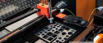
Preparatory operations for unique parts and small series are performed on round cutters. In the case of large series, cutting is more efficiently performed on hydraulic cutting machines, due to the fact that laser or plasma cutting is associated with high temperature exposure in the cutting area. This may impair the ductility of the material.
Rotary metal drawing process
Rotary drawing technology is used in the production of pipe-shaped products with varying diameters and wall thicknesses. In addition, it is possible to form stiffening ribs on the outside. Rotary metal drawing is also used in complex technological processes in conjunction with stamping, welding, riveting and metalworking operations.
Subtleties of rotary drawing technology
If you have ever wondered what a rotary metal drawing looks like, just imagine a metalworking machine where a round workpiece and a base of a suitable shape are installed. On modern equipment, the wizard simply sets a suitable program, which itself executes all commands on the equipment. However, rotary hood can also be done manually using simple equipment without a programming mode. There are several types of rotary hood:
- multi-pass - several processing modes;
- one-stage;
- rolling;
- seaming;
- profiling.
As a result of the variety of processes and the rotary drawing technology itself, it is possible to obtain parts of complex shapes, for example, in the form of a cone, sphere, or oval. At the same time, the production itself does not require a large number of different technical equipment.
Other rotary hood options
In addition to creating spherical parts and other workpieces, metal drawing technology is capable of:
- create irregularly shaped parts with constant or variable wall sections;
- perform complex parts that cannot be created using other technologies;
- obtain elements with a minimum surface roughness;
- carry out finishing operations with metal, including trimming, corrugating, knurling and other options;
- process parts of varying complexity automatically.
Thanks to modern equipment, the large jewelry factory managed to reduce the amount of manual labor. For example, you can replace the hand casting process with rotary drawing technology to get spherical earrings or a beautiful goblet.
Methods for rotary drawing of metal
The variety of techniques for rotary drawing of metal comes down to one of two types:
- Straight. The metal moves along the forming roller.
- Back. The metal moves against the movement of the forming roller.
Direct method
The outer contour of the punch corresponds to the inner contour of the future product (taking into account the necessary allowances). Because of this, the mandrel is made longer than the product. The design of the punch becomes more complicated, the weight, cost and labor intensity of debugging the technological process increases.
Direct method of rotary drawing of metal
This method is applicable for molding parts in the form of a cone and cylinder with a large ratio of length to diameter and diameter to wall thickness.
Back
In this case, the mandrel must match in size and shape with the inner surface of the workpiece, which makes it possible to make the mandrel much shorter than the future product.
Thick-walled rotary hood
The method is used in the production of products with a small length-to-diameter ratio and relatively thick walls.
Rotary metal drawing operations are also divided into forming:
- With thinning, the outer size is maintained, the wall thickness is reduced.
- Without thinning - the wall thickness is maintained during processing, but the outer diameter changes.
- With rolling, the outer diameter is maintained, the wall thickness increases.
Main types of rotary metal drawing
The workpiece is secured between the mandrel fixed to the drive and the caliper clamp.
Advantages of the metal drawing technique
There are two main methods of rotary drawing: direct and reverse. Both options have the following advantages:
- workflow automation;
- accuracy of manufacturing parts that repeat the profile (workpiece);
- permissibility of production of small and large batches of goods;
- reducing production cycles and increasing enterprise productivity;
- reduction of material consumption, which reduces the final cost of products;
- finished parts have high strength and uniform structure;
- low cost of purchasing consumables.
Thanks to the rotary drawing technology, ideal shapes are obtained that act as blanks for further jewelry creation. In addition to the jewelry industry, machines are used for the production of metal parts and blanks for various industries.
Areas of application of rotary drawing technology
Most often, machines for rotary drawing of metal are installed in the space and aviation fields. And also in the field of shipbuilding and mechanical engineering, the automotive and chemical industries, energy and for the creation of parts for radio equipment and electronics. The equipment is often used in jewelry on an industrial scale to produce unique batches of goods on time.
Almost any metal can be used as a workpiece; aluminum, brass, bronze and copper are most often used due to their flexibility and ductility. Precious metals can also be processed by drawing.
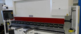
Machines for rotary drawing of metal
To implement the technology, the following types of machines are used:
- Pressing and rolling machines for rotary drawing of metal.
- Rotary forging machines.
- Round cutters.
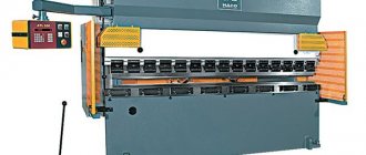
On manual lathes, molding is performed by the muscular strength of the worker. Used to produce unique products or especially small series. For medium and large series, pressing and rolling (rolling) machines with numerical control are used. Hydraulics or electric drives, controlled by a controller according to a program loaded into the central CNC unit, allow precise control of the force and direction of the clamp, as well as the direction of movement of the roller, including the most complex curved trajectories. Such machines ensure absolute identity of products in a series, which is especially important for jet engine parts and other high-tech products
Scheme of forging on rotary machines
Rotary forging machines allow you to form conical-shaped products from pipes by crimping the pipe with a special tool - a forging die. The peculiarity and main advantage lies in the unique ability to produce products that have:
- the length is many times greater than the diameter.
- along the length, the diameter and opening angle of the cone can be repeatedly changed.
- knurling of stiffeners is required.
Circular cutters are designed for cutting rolled sheets into flat pieces in the shape of a circle or ellipse. Also used are both manual and electro-hydraulic.
What are the features of CNC pressing and rolling machine?
Would you like to know more about CNC press-forming machines? Find out about rotary hoods, classification, features and advantages of such units.
Pressing and rolling machines with numerical control are equipment used for processing sheet metal blanks. Pressing and rolling processing of a roller is a modern method carried out on CNC pressing and rolling machines.
This method involves the use of devices that have hydraulic and electro-hydraulic supporting parts of the metal-cutting device. They move the pressure rollers, which are the main tools in the processing of parts.
Scope of application of rotary metal drawing
The method is used to produce:
- jet engine parts in weapons systems;
- tank bottoms and covers;
- various screens in radio engineering, including radar screens;
- thin-walled vessels of complex shape: cans, teapots, cylinders, kettles;
- parts of construction mixer bodies;
- parts of fans and exhaust hoods.
Products made by rotary drawing
The method is also used in the production of contemporary art objects and in the studio for customizing unique motorcycles and cars.
If you find an error, please select a piece of text and press Ctrl+Enter.
>