Milling is a material processing process in which the workpiece is impacted using a cutter. Each of its teeth cuts a piece of metal from the original part. The rotation of the cutting element occurs above a moving surface, i.e. the work table with the workpiece moves, but the cutter remains motionless. There are machines that have a moving table and cutter.
Milling
Milling is one of the most common metalworking methods. This method processes:
- rough;
- finishing;
- semi-finish.
The surfaces of steel, cast iron, wood, plastic and other products are processed by milling. Milling can be: vertical and horizontal. In this case, it is possible to install the cutter at any angle of inclination. Most factories have machines of both types. Depending on the type of cutter, milling can be:
- End Large areas are processed using an end mill. Also, using this method, grooves and undercuts are applied. Advantage of the method: low noise level during work.
- Shaped. The profile is milled.
- Cylindrical.
- Serrated.
- End. This method is used to make grooves, undercuts, pockets, and wells. Grooves can extend onto 1 or more surfaces. They can also be end-to-end.
To obtain high quality parts, pay attention to some nuances. The rough work must be done first. They are produced on machines with a high rigidity frame. When using low-rigidity equipment during work, vibration increases and milling accuracy decreases. As a result, all this can break working tools and equipment.
During finishing work, the cutting depth should be less than during roughing. For this reason, the machine does not operate at full power, but at reduced speed.
ELEMENTS OF CUTTING MODES DURING MILLING
Milling
Milling –
the process of processing surfaces with a multi-blade tool - a milling cutter on milling machines.
The main movement (v) in this type of cutting processing is carried out by rotation of the cutter, and the feed movement ( s
) is carried out by translational movement of the workpiece (Fig. 12). On horizontal milling machines, the axis of rotation of the cutter is located horizontally, and on vertical milling machines it is vertical, but can be rotated at an angle of ± 45° in the vertical plane.
Depending on the direction of movement of the milling machine table, different feeds can be realized: longitudinal, transverse and vertical.
On the workpiece being processed, during milling, a distinction is made between the machined surface, the machined surface and the cutting surface (Fig. 12).
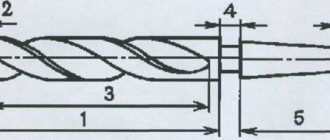
Rice. 12 Technological
surfaces when milling:1
– surface to be treated;
2 –
cutting surface;
3 –
processed surface;
4 –
workpiece;
5 –
cutter.
ELEMENTS OF CUTTING MODES DURING MILLING
The elements of cutting modes during milling include: cutting speed (v), feed ( s
), cutting depth (
t
) and milling width (
B
), fig. 17.
The cutting speed is the peripheral rotation speed of the cutter. The cutting speed depends on many factors (as in turning) and primarily on the depth of cut ( t
), feed (
s
), tool life (
T
).
Feed amount ( s
) is determined mainly by the specified roughness value of the machined surface, as well as the type of cutter and the hardness of the material being processed and other factors.
For rough milling ( Rz
= = 40…30)
sz
= 0.5…0.15 mm/tooth; When rough milling, larger feed values are used for face and cylindrical cutters, and smaller ones for end (grooving) and disk cutters.
Rice. 15 Layout of the main components of a horizontal milling machine:
1 –
bed;
2
– gearbox;
3
– trunk;
4
– table for installing and securing the workpiece;
5 –
pendant (earring) for supporting the mandrel with the cutter;
6
– skids;
7 – console; 8
– feed box.
Rice. 16 Layout of the main components of a vertical milling machine:
1 –
bed;
2 –
gearbox;
3
– spindle head;
4
– spindle;
5 –
table for installation and fastening of the workpiece;
6 –
skids;
7
– console;
8 –
feed box.
Rice. 17 Elements of cutting modes during milling:
A
– counter milling;
b
– downhill milling
Types of cutters and their geometric parameters
Depending on the purpose and type of surface being processed, the following types of cutters are distinguished: cylindrical, end, disk, end, corner, keyed, shaped. Cutting blades can be straight or helical.
The cutters can have pointed and backed tooth shapes. A pointed tooth has flat front and back surfaces; The front surface of a backed tooth is flat, and the back surface is made in an Archimedes spiral. When regrinding a backed tooth along the front surface, the tooth profile is preserved (this is important for shaped and gear cutters).
In addition, cutters can be solid or prefabricated, with brazed and inserted knives.
Elements and geometry of the cutter
The geometric parameters of a cylindrical cutter include:
1 End pitch t –
the distance between the teeth at the end of the cutter.
2 Axial pitch t
0 – distance between teeth along the cutter axis
t
0 =
t
ctgω.
Equipment, devices, tools and visual aids.
Vertical milling machine model 6M12P.
Clamps, stands, corner plates (regular, universal), machine vices (regular, universal), special devices.
Adapter bushings, mandrels, cartridges. Measuring tools: calipers, etc.
Controls
Figure 23 – Main parts and controls of the machine.
Figure 23 shows the controls of the 6M12P vertical milling machine. The machine provides duplication of control. The controls are located on the front panel of the machine and on the left side.
Spindle rotation is turned on using button 15 on the front, and button 5 on the left side; spindle rotation is turned off using button 6.
Pulse (short-term) switching on of the spindle is performed by button 3. The spindle is switched to the required number of revolutions by handle 1. The required number of revolutions is set by turning dial 4, guided by the arrow indicating the spindle speeds. The direction of rotation of the spindle is changed by switch 26.
The machine spindle is mounted in a rotating head, which rotates in a vertical plane at an angle of 45° in any direction.
The spindle is a two-support shaft mounted in a retractable sleeve. The sleeve is extended together with the spindle using handwheel 9, and clamping is done using handle 10.
Switching on the machine lighting (the lamp is carried out by switch 7, and switching on the cooling pump is switched on by switch 27.
The movements of the table are controlled by handles, the direction of rotation of which coincides with the direction of movement of the table. Feed switching is carried out using the fungus 20 and the feed switching dial.
At the same time, the fungus button is pressed, and the plastic fungus is pulled back all the way. Then rotate the dial by the fungus and set the required feed amount. The dial can be rotated in any direction. The longitudinal feed of the table is turned on using handle 12 or 23 (duplicate).
The vertical and transverse feed is turned on using handle 21 or 24 (duplicate). To set up the machine for automatic cycles of table movement, cams 11 are used. Rapid movement of the table in the longitudinal, transverse and vertical directions is carried out by button 2 or 16 (duplicate). Manual movement of the table in the longitudinal direction is carried out by handwheels 13 and 25 (duplicate), and in the transverse direction by handwheel 17.
Manual vertical movement of the table is carried out by handle 18. The console on the supporting stands is secured by handle 19, the slide on the console by handle 22. When you press button 14 (“stop”), the motor is disconnected from the network and the spindle is braked. The machine is turned off from the mains using the main switch 28.
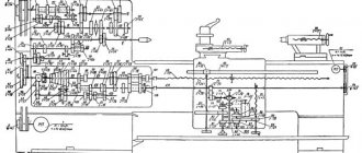
Kinematic diagram of the machine
Main movement chain
. From a 7.5 kW electric motor, motion is transmitted through an elastic coupling to shaft I, and from shaft I to shaft II through a gear 27:53. On shaft II there is a triple block of gears, with which it is possible to transmit rotation to shaft III at three different speeds through gears 22:32, 16:38 and 19:35. From shaft III to shaft IY, movement can also be transmitted in three different gear options: 38:26, 27:37, 17:46. Therefore, shaft IY has nine different speeds (3x3=9). Shaft Y receives motion from shaft IY through a double gear bank with gears of 82:38 and 19:69. Thus, the Y shaft has 18 different speeds (9x2=18). From the Y shaft, the movement is transmitted to the YI shaft by a 30:30 bevel gear transmission, and from the YI shaft to the YII spindle through a 54:54 gear.
Selection of milling modes
Selecting milling modes means that for given processing conditions (material being processed, workpiece dimensions, processing allowance, etc.) select the optimal type and size of cutter, grade of cutter material and geometric parameters of the cutting part, as well as optimal parameters of milling modes: milling width, depth milling, feed per tooth, cutting speed, spindle speed, minute feed, effective milling power and machine time.
Selecting the type and size of cutter
For roughing, end mills with insert knives or large teeth are chosen. When finishing, you should use end mills with fine teeth.
However, in all cases, preference should be given to end mills equipped with hard alloys, since the machine processing time in this case is significantly reduced by increasing the cutting speed.
Next, for a given material being processed and the selected material of the cutting part of the cutter, the geometric parameters of the cutting part (α, γ, etc.) are determined from reference tables.
Diameter of the end mill (GOST 17025-71, GOST 20537-75, GOST 20533-93, etc.), intended for:
— milling the groove, determined by the width of the groove;
— shoulder milling, is accepted as the maximum permissible for a given machine.
Selection of cutting modes
Cutting modes are determined from the tables that are given in the handbooks of the miller, technologist, standardizer or in the handbooks on cutting modes.
The selection of cutting modes during milling is carried out in the following sequence:
1) milling width B , as a rule, is not chosen, since it depends on the dimensions of the workpiece, groove or shoulder.
2) determination of the maximum permissible cutting depth t based on the processing allowance. It is advisable to remove the processing allowance in one pass. When finishing milling, the cutting depth does not exceed 1 to 2 mm.
3) determination of the maximum permissible feed per tooth Sz depending on the nature of the processing (roughing or finishing milling).
During rough milling, the feed rate is limited by the strength of the cutter tooth, the strength of the cutter itself (end mills, small diameter cutters, etc.), insufficient power, machine rigidity, etc.
During finishing machining, the feed rate must meet the requirements for accuracy and roughness of the machined surface.
During rough milling, the feed per tooth is greater than during finishing milling, since the lower the feed per tooth, the higher the roughness class of the machined surface.
Milling
Milling –
the process of processing surfaces with a multi-blade tool - a milling cutter on milling machines.
The main movement (v) in this type of cutting processing is carried out by rotation of the cutter, and the feed movement ( s
) is carried out by translational movement of the workpiece (Fig. 12). On horizontal milling machines, the axis of rotation of the cutter is located horizontally, and on vertical milling machines it is vertical, but can be rotated at an angle of ± 45° in the vertical plane.
Depending on the direction of movement of the milling machine table, different feeds can be realized: longitudinal, transverse and vertical.
On the workpiece being processed, during milling, a distinction is made between the machined surface, the machined surface and the cutting surface (Fig. 12).
Rice. 12 Technological
surfaces when milling:1
– surface to be treated;
2 –
cutting surface;
3 –
processed surface;
4 –
workpiece;
5 –
cutter.
ELEMENTS OF CUTTING MODES DURING MILLING
The elements of cutting modes during milling include: cutting speed (v), feed ( s
), cutting depth (
t
) and milling width (
B
), fig. 17.
The cutting speed is the peripheral rotation speed of the cutter. The cutting speed depends on many factors (as in turning) and primarily on the depth of cut ( t
), feed (
s
), tool life (
T
).
Feed amount ( s
) is determined mainly by the specified roughness value of the machined surface, as well as the type of cutter and the hardness of the material being processed and other factors.
For rough milling ( Rz
= = 40…30)
sz
= 0.5…0.15 mm/tooth; When rough milling, larger feed values are used for face and cylindrical cutters, and smaller ones for end (grooving) and disk cutters.
Rice. 15 Layout of the main components of a horizontal milling machine:
1 –
bed;
2
– gearbox;
3
– trunk;
4
– table for installing and securing the workpiece;
5 –
pendant (earring) for supporting the mandrel with the cutter;
6
– skids;
7 – console; 8
– feed box.
Rice. 16 Layout of the main components of a vertical milling machine:
1 –
bed;
2 –
gearbox;
3
– spindle head;
4
– spindle;
5 –
table for installation and fastening of the workpiece;
6 –
skids;
7
– console;
8 –
feed box.
Rice. 17 Elements of cutting modes during milling:
A
– counter milling;
b
– downhill milling
Milling cycles
Any type of milling includes the following steps:
- Loading and unloading time. The duration of the stage depends on the machine and the size of the workpiece.
- Cutting time. It is obtained by dividing the length of the cut by the feed speed of the original part.
- Simple.
- Replacing tools. The time required to replace a cutting element whose operational period is coming to an end. The cycle is performed when the cutter is completely worn out.
To apply records to the workpiece, metal etching (chemical milling) is performed. This method is used to reduce the size of parts in the form of cylinders and increase the radius of holes.
Milling machines
They are designed for milling various workpieces from simple to complex configurations. Milling on such equipment is distinguished by its high productivity and makes it possible to obtain various geometric shapes.
Using cutters equipped with modern cutting metals or other materials, hardened steels are processed.
The most popular types of machines are universal equipment. Horizontal, vertical and wide-universal ones are a little less common.
The simplest are horizontal (spindle mounted horizontally) and vertical (spindle mounted vertically) machines. By processing them, simple products are obtained: frames, corners, etc. More complex equipment has a rotating work table, which is used for processing and producing a variety of screw surfaces. You can expand the functionality of the equipment by adding various devices.
Universal machines can rotate the work table in both planes. Widely universal machines have a special design. Additional equipment and other structures are installed on it.
Most milling is done on machines with a vertical configuration. They perform the following types of work:
- drilling;
- turning;
- countersinking.
They can also process not only metal, but also other materials. Single and mass production possible. Such machines have either manual control (the work and processes are performed by the operator) or a CNC control system. In this equipment, the movement is set by the cutting element, the workpiece rotates if necessary.
For metal processing of large parts, non-cantilever machines are used. This type of equipment also allows you to make cuts on inclined surfaces. Since there is no console on it, the machine moves on a slide and a frame mounted on the foundation. This allows for greater strength and stability.
The following machines are used today:
- Longitudinal milling. Process large workpieces.
- Copy-milling machines. Used for complex profiles.
- Engraving. Engraving of inscriptions and patterns is carried out.
- Thread milling. Perform thread processing.
- CNC. Modern type of equipment. Performs processing of complex workpieces and allows you to obtain a variety of shapes. Visually and structurally they are no different from “standard” machines. The main difference is complete automation of work thanks to built-in programs.
Such machines, and their combination in industry, save processing and preparation time. Since there is no need to make templates, and manual labor is eliminated.
Basic concepts about the milling process
Home » Articles » Professionally about metalworking » Metal cuttingWe recommend purchasing:
Installations for automatic welding of longitudinal seams of shells - in stock!
High performance, convenience, ease of operation and reliability in operation.
Welding screens and protective curtains are in stock!
Radiation protection when welding and cutting. Big choice. Delivery throughout Russia!
Milling is blade processing with a main rotational cutting movement imparted to the tool and having a constant trajectory radius, as well as at least one feed movement directed perpendicular to the axis of the main movement.
Milling is a productive and universal technological method of mechanical processing of workpieces by cutting. In mechanical engineering, planes, ledges, grooves of rectangular and profile sections, grooves, shaped surfaces, etc. are processed by milling. Milling is also used for cutting rolled rods, threading and gear milling.
To process flat and shaped surfaces on milling machines, milling cutters are used - multi-toothed (multi-edged) tools. Each tooth of a cutter is a simple cutter.
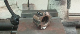
Purpose of cutters
. The main types of cutters are shown in Fig. 2.17. To process open planes on horizontal milling machines, solid cylindrical cutters (Fig. 2.17, a) and prefabricated cutters with insert knives (Fig. 2.17, b) are used.
For high-performance processing of continuous and discontinuous planes on vertical milling and special machines, face milling heads (Fig. 2.17, c) equipped with carbide knives are used.
Machining of mating planes located at different levels, parallel or inclined (cube faces, hexagons, bevels, ledges, etc.) is carried out using solid end mills (Fig. 2.17, d) and with insert knives (Fig. 2.17, e ).
Milling of grooves and ledges is carried out using end (Fig. 2.17, f, g), key (Fig. 2.17, h) and disk (Fig. 2.17, i) cutters. End mills are widely used for processing semi-open planes, grooves and for copying work (see Fig. 2.17, e). To process closed keyways, keyway cutters are used (see Fig. 2.17, h).
Cutting splines and narrow slots is done with cutting (Fig. 2.17, j) and spline cutters.
Angle cutters (Fig. 2.17, l) are used for milling straight and helical grooves between teeth in the manufacture of cutters, reamers, countersinks and other tools. Milling of shaped surfaces is carried out using shaped cutters (Fig. 2.17, m).
When classifying cutters, in addition to their purpose, their design is taken into account; the method of fixing them on the machine; tooth design; arrangement of teeth relative to the axis; direction of teeth.
cutter designs exist
: whole; composite (for example, with soldered or glued cutting elements); prefabricated (for example, equipped with multifaceted carbide plates); typesetting (sets of cutters), consisting of several individual standard or special cutters and designed for simultaneous processing of several surfaces.
Fastening cutters to machines
. The connecting parts—fastening bases—for cutters can be cylindrical holes with longitudinal or transverse keyways, conical and cylindrical shanks (see Fig. 2.17).
Cylindrical, disk, face, corner and shaped cutters are mounted on milling mandrels. To reduce runout of the milling mandrel, the supporting ends of the cutters must be strictly parallel to each other and perpendicular to the axis of the cutter. The deviation of the supporting end surfaces from the cutter axis should not exceed 0.04...0.05 mm. Rotation of cutters mounted on a mandrel is transmitted by a longitudinal or end key.
End mills with small teeth are mounted on shortened mandrels using a screw, and those with large teeth and insert knives are mounted on special mandrels.
End and key cutters with a diameter of up to 20 mm, for which a cylindrical shank serves as the mounting base, are secured to the end mandrels using a collet clamp. End, face and key cutters with a diameter of over 200 mm, for which the mounting base is a conical shank, are installed in the machine spindle directly or using adapter conical bushings. The conical shank is tightened in the conical socket of the spindle using a screw.
Face milling heads (see Fig. 2.17, c) are mounted directly on the machine spindle. The base hole, keyway and hole for mounting screws are made according to the dimensions of the front ends of the milling machine spindles.
Teeth
cutters can be sharpened (Fig. 2.18, a) and backed (Fig. 2.19, a). Sharpened teeth are sharpened along the rear surface at a rear angle α (see Fig. 2.18, lines T-T). These teeth are easy to manufacture and provide high surface finish. The disadvantages of pointed teeth are a reduction in tooth height and loss of profile dimensions after regrinding.
Three types of sharpened teeth are used: with a straight back (Fig. 2.18, b), a two-angled back (Fig. 2.18, c) and a curved back (Fig. 2.18, d). Teeth with a straight back are characteristic of fine-tooth cutters that allow 6...8 tooth regrinds and are intended for light work.
Double-back teeth are common on coarse-tooth cutters designed for heavy-duty work. The back of the tooth, formed by two surfaces, is built so that the tooth has a shape close to a parabola. Milling cutters with teeth of this type, with high tooth strength, have a larger groove volume.
Teeth with a curved back, made along a parabola, have equal strength in all sections, which makes it possible to increase the height of the tooth, and therefore, increase the number of regrinds and increase the volume of the groove.
For backed cutters with a rear surface formed along an Archimedes spiral (see Fig. 2.19, a), sharpening is carried out along the front surface (line T-T). The tooth of these cutters remains unchanged in shape (Fig. 2.19, b) and the dimensions of the shaped profile during all resharpenings until the cutter is fully used. The backed tooth is used mainly in shaped cutters.
By the location of the teeth relative to the axis
distinguish: cylindrical cutters with teeth located on the surface of the cylinder (see Fig. 2.17, a and b); end mills with teeth located at the end of the cylinder (see Fig. 2.17, d and e); corner cutters with teeth located on a cone (see Fig. 2.17, l); shaped cutters with teeth located on the surface with a shaped generatrix (see Fig. 2.17, m) (with a convex and concave profile). Some types of cutters have teeth on both the cylindrical and end surfaces, for example, two- and three-sided disk cutters (see Fig. 2.17, i and j), end cutters (see Fig. 2.17, e), keyed ones (see Fig. 2.17, h).
Tooth direction
cutters can be: straight-toothed (see Fig. 2.17, i and j); helical (see Fig. 2.17, l) and with a screw tooth (see Fig. 2.17, a). The angle of inclination of the helical tooth serves to ensure quiet (vibration-free) milling.
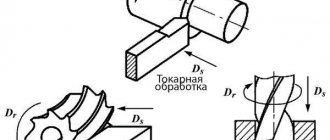
When milling, two schemes are used:
- counter milling
(Fig. 2.20, a). The directions of feed Ds and cutter speed v are counter. Cutting begins at point 1 (zero thickness of the cut layer) and ends at point 2 (the greatest thickness of the cut layer); - down milling
(Fig. 2.20, b). The direction of feed movement Ds coincides with the direction of speed v of the cutter. Cutting begins at point 2 (the greatest thickness of the cut layer) and ends at point 1 (zero thickness of the cut layer).
When working according to the first cutting scheme, cutting in is difficult, as the tooth slips and a large release of heat occurs, which accelerates the dulling of the cutter. When working according to the second scheme, a higher quality of the machined surface and slow dulling of the cutter are ensured. However, the work occurs in jerks (at the moment the tooth cuts into the metal), so down-milling is only possible on machines specially adapted for this purpose.
The geometric parameters of cutters are selected depending on the following factors: the material of the workpiece and the cutting part of the cutter, its design, and milling conditions. The front γ and rear α cutting angles are formed by sharpening cutters (Fig. 2.21).
The presence of a rake angle γ facilitates tool penetration and chip separation. As the rake angle increases, the working conditions of the tool improve, the cutting force decreases, and its durability increases.
However, too large a rake angle will weaken the cutting tool body adjacent to the blade, and it will chip and break easily. In this case, heat removal deteriorates. Based on this, very specific rake angle values are recommended for each tool.
At small angles α, friction increases, cutting forces and cutting temperature increase, the flank surfaces of the tool quickly wear out and its durability decreases. At very large values of angles a, the strength of the tool decreases and heat dissipation deteriorates. The angle between the front and rear surfaces of the cutter blade is called the sharpening angle β in the cutting plane.
Source: Cherpakov B.I., Alperovich T.A. "Metal-cutting machines", textbook. -M. 2003
Stages of milling on machines
Milling consists of several stages:
- the workpiece is carefully brought (the side on which processing will be performed) to the router;
- the work table is retracted and the spindle is turned off;
- the cutting depth is set;
- the spindle starts;
- the workpiece is brought to the cutter.
Cylindrical elements are processed with a cutter 1.5 cm larger than the workpiece itself.
Thanks to new technologies, milling is popular among manufacturing industries. The machines process any metal from aluminum to titanium. Regardless of the materials, milling allows you to obtain parts of any type, type, or purpose. Laser milling is performed on CNC machines. This is expensive, however, the parts are of high quality, and the workpieces do not require grinding at the first stage of processing.
Plane milling
The planes are usually milled with end mills. The cutter diameter D (mm) is selected depending on the milling width B according to table. X.2 and from the relation
D≈(1.3÷1.8) B (53)
Table X.2. Choosing the diameter of an end mill when milling planes. Size, mm
| Milling width B | Cutter diameter D | Milling width B | Cutter diameter D |
| 45 | 80 | 200 | 250 |
| 65 | 100 | 240 | 320 |
| 80 | 125 | 320 | 400 |
| 110 | 160 | 400 | 500 |
| 150 | 200 | 500 | 630 |
When processing planes on horizontal milling machines, both end cutters (for vertical surfaces) and cylindrical cutters (for horizontal surfaces) are used. When milling with cylindrical cutters, choose a cutter width slightly larger than the width of the machined surface. The diameter of the cutter can be selected according to the table. X.3.
Table X.3. Choosing the diameter of a cylindrical cutter when milling planes. Dimensions, mm
| Milling width B | Cutter diameter D at cutting depth t | ||
| 2 | 5 | 10 | |
| 50 | 63 | 80 | 100 |
| 100 | 80 | 100 | 100 |
| 150 | 100 | 100 | 125 |
Milling the workpiece plane 1 with end mill 2 (D > B) should be carried out with a slightly offset axis relative to the axis of symmetry, as shown in Fig. X.2.
| Dimension C = (0.03÷0.06)D. This offset facilitates the conditions for cutting into the cutter. Rice. X.2. Installation of the end mill relative to the workpiece: a - symmetrically (not recommended); b - asymmetrical (recommended) |
Allowances for milling planes. The values of allowances for processing the planes of workpieces made of steel and cast iron (castings, forgings) are given in Table. X.4, and blanks made of non-ferrous metals - in table. X.5.
Table X.4. Allowance on the side when processing the planes of parts made of ferrous metals
| Nature of milling processing | The largest size of the processed surface, mm | |||||||
| up to 50 | St. 50 to 120 | St. 120 to 260 | St. 260 to 500 | St. 500 to 800 | St. 800 to 1250 | St. 1250 to 2000 | St. 2000 to 3160 | |
| Rough after casting: | ||||||||
| into sand molds | 0.9-1.0 | 1.1-1,2 | 1,5-1,6 | 2.2-2,3 | 3.1-3.2 | 4.6-4,6 | 7.0-7,1 | 10-11 |
| into a permanent mold (mold) | 0,7 | 0,8 | 1,0 | 1.6 | 2.2 | 3.1 | 4.6 | 7 |
| into shell form | 0,5 | 0,6 | 0,8 | 1.4 | 2.0 | 2,9 | — | — |
| lost wax | 0,3 | 0,4 | 0,6 | 0.8 | — | — | — | — |
| Semi-finish after roughing | 0,25 | 0,25 | 0.3 | 0.3 | 0.35 | 0.4 | 0,5 | 0.65 |
| Finish after semi-finish | 0.16 | 0.16 | 0.16 | 0.16 | 0.16 | 0,16 | 0.2 | 0.2 |
Table X.5. Allowance on the side when processing the planes of parts made of non-ferrous metals and alloys
| Nature of milling processing | The largest size of the processed surface, mm | ||||||||||
| up to 50 | St. 50 to 120 | St. 120 to 180 | St. 180 to 260 | St. 260 to 360 | St. 360 to 500 | St. 500 to 630 | St. 630 to 800 | St. 800 to 1050 | St. 1050 to 1250 | St. 1250 to 1600 | |
| Rough after casting: | |||||||||||
| into sand forms (into the ground) | 0,65 | 0.75 | 0.8 | 0.85 | 0.95 | 1,1 | 1.25 | 1.4 | 1.6 | 1.8 | 2,1 |
| into chill molds and shell molds | 0,35 | 0.45 | 0.5 | 0.55 | 0.65 | 0.85 | 0.95 | 1.1 | 1.3 | 1.5 | — |
| by investment models | 0.25 | 0,3 | 0.4 | 0.45 | 0.55 | 0.7 | 0.85 | 1,0 | — | — | — |
| under pressure | 0.15 | 0.25 | 0.3 | 0.35 | 0.45 | 0,6 | 0.75 | — | — | — | — |
| Finishing after roughing | 0.07 | 0.09 | 0.11 | 0.14 | 0.18 | 0.23 | 0.3 | 0,37 | 0.45 | 0,55 | 0.65 |
Plane milling accuracy
.
During rough milling, dimensional accuracy of 11th to 12th quality is usually achieved, while for finishing - 8th to 9th quality. In some cases, with careful work (for example, with fine milling), you can obtain 6th and 7th qualifications. In table X.6 shows data based on numerous observations on the accuracy of the resulting dimensions when milling planes , and in table.
X.7 - the same about the accuracy of shape and relative position of planes achieved when milling on machines of various types. Milling a rectangular block
. The milling operator often has to deal with the task of milling workpieces such as bars (Fig. X.6). Essential in this case is the correct choice of bases and sequence of surface treatment.
When securing a workpiece in a machine vice, surface 1, which has the largest area, must first be processed (Fig. X.6, a). In this case, the workpiece is installed in a vice so that the surface 4 opposite to it rests on the guide surface of the vice or on two parallel pads of equal height.
In the second transition (Fig. X.6, b), the workpiece is installed with the machined surface 1 against the stationary jaw of the vice and is pressed against it either directly by the movable jaw, or, as shown in the figure, through a piece of round metal 5 in the center of the jaws. This eliminates possible distortion of the workpiece during fastening. In this position, surface 2 is milled, adjacent to base 1. The second and third (Fig. X.6, c) transitions provide a right angle between surfaces 1 and 2 and 1 and 3.
| In the last transition (Fig. X.6, d), the same surface 1 serves as the base. The block is installed with surface 1 on paired (having equal height) parallel pads and, before final fastening in a vice, is verified, for which the parallelism of the base surface 1 to the table is checked . After alignment, the workpiece is finally secured. If everything is done correctly, then surfaces 1 and 4 should be parallel and at the same time perpendicular to surfaces 2 and 3. Rice. X.6. The sequence of processing plane-parallel and mutually perpendicular surfaces of the bar |
The given sequence of processing a bar is rational both for roughing and finishing. When finishing, in order to avoid damage to the machined surfaces during the process of securing the workpiece, gaskets made of sheet brass or copper are usually put on the jaws of the vice.
Milling squares
. If you need to mill a square on a workpiece made of a cylindrical rod (the square is inscribed in a circle), the question arises: how to set up the machine and measure the workpiece during its processing?
In Fig. X.7, and the side of the square is designated 5. When milling the first two faces of the square, size S1 is used, and size S is used when milling the third and fourth faces.
To determine S and S1, use the following formulas:
S=0.707D (57) S1= 0.8540D (58)
where D is the diameter of the workpiece, mm.
Hex milling
. When milling hexagons on a cylindrical workpiece, there is a need to calculate a number of quantities necessary for setting up the machine and taking measurements.
When milling the first three faces, size S1 is measured (Fig. X.7, b), and when processing the fourth, fifth and sixth faces, size S is measured. These dimensions are calculated using the formulas:
S=0.866D (59) S1= 0.933D (60)
To set the cutter to size you need to take size a
a = 0.067D (61)
| When installing a cutter, size a is measured along the dial. Upon receipt of a workpiece processed to the diameter of the circumscribed circle of a square or hexagon, you can determine the size a (Fig. X.7) using the formula a = (D - S)/2. Rice. X.7. Constructing dimensions when milling a square and hexagon from a cylindrical workpiece |
Shoulder milling
. Shoulders are milled on both horizontal milling and vertical milling machines. The main schemes for processing ledges are given in table. X.8.
Milling rectangular slots
. Processing of rectangular through (output) grooves up to 16 mm wide with permissible width deviations of 10th grade is carried out with disc groove cutters with sharp teeth and backed teeth. Closing (no exit) slots are milled with end mills. Wider through rectangular grooves are machined with three-sided disk cutters. However, milling a groove with a permissible width deviation within the 9th-10th grade in one working stroke requires the use of the first cutter (within the width tolerance range), which is irrational, since the very first resharpening after blunting will change its width size and lead to it is outside the tolerance range.