Cutting modes in machining are a set of operating parameters that determine the speed, force and depth to which the cutter is immersed into the part during the process of removing a layer of metal from its surface.
Their basic values are determined by calculation based on the geometry of the cutting edge of the tool and the workpiece, as well as the speed of their approach. Real metal processing processes are influenced by many factors related to the characteristics of the tool used, machine equipment and the material being processed.
Therefore, empirical formulas are used to calculate technological cutting conditions. And the basic values are included in their composition along with such reference values as groups of correction factors, durability values, parameters of processing conditions, etc.
Cutting modes affect not only the specified accuracy and processing class of the product. They determine the force with which the tool edge acts on the metal, which directly affects power consumption, the level of heat generation and the wear rate of the tool.
Therefore, the calculation of their parameters is one of the main tasks of technological services of enterprises. Despite the many varieties of metal-cutting equipment and tools, all machining is based on common principles.
Therefore, methods for calculating cutting modes are unified and systematized into three main groups: for turning, for drilling and for milling. All other types of calculations are derivative.
Parameters for calculating cutting conditions
The main calculation of machining modes is based on three parameters: cutting speed (V), feed (S) and depth of cut (t). To obtain practical values of these parameters that can be used in production, at the first stage their calculated values are determined.
Then, using empirical formulas, lookup tables and data from equipment data sheets, they are used to select technological cutting modes that will best suit the type of material being processed, the capabilities of the machine, as well as the type and characteristics of the tool.
Not only the quality of processing, but also indicators such as productivity, production costs and operating costs depend on the correct calculation and selection of these parameters. In addition, the force exerted on the tool during processing affects not only the rate of its wear, but also the condition of the equipment and fixtures.
The consequence of working at too high speeds and feeds is unacceptable vibration and increased load on the components and mechanisms of the equipment. And this can lead not only to loss of accuracy, but also to machine failure.
As a rule, cutting conditions are checked and adjusted during trial processing of the part. Therefore, their choice depends not only on the correctness of the calculations, but also on the experience of the technologist and machine operator.
Speed
The time cycle for processing a part consists of three basic components: preparatory-final, auxiliary and main time.
The latter includes all metal cutting operations at specified conditions. Due to the nature of machining, prime time is the most expensive component of the part processing cycle. Moreover, its value, and therefore the cost of the product, directly depends on the cutting speed. Therefore, the correct selection of this parameter is important not only from a technological, but also from an economic point of view.
In general, the formula for the calculated cutting speed looks like this:
In this formula, the value of parameter D depends on the type of processing. For turning, this is the diameter of the part; for other types, this is the diameter of the cutting tool (drill, cutter). Parameter n is the spindle rotation speed in revolutions per minute.
In this way, the theoretical value of the cutting speed is determined, which is the starting point for subsequent calculations. In particular, it is used to calculate the theoretical depth of cut, which is denoted by t. Due to the fact that the actual cutting speed depends on many factors, it is calculated using an empirical formula in which the only calculated value is t:
Here Cv is a dimensionless constant depending on various aspects of processing; T is the standard tool life time; t—cutting depth; So—feed; Kv is a summary coefficient, which is the product of eight correction factors.
Innings
Feed (denoted S) is the path that the cutting edge travels per unit. Depending on the type of machining, the feed may have different dimensions. The length of the traveled path is always measured in millimeters, but it can be correlated with either one revolution (in turning) or one minute (in drilling and milling).
Thus, during drilling, this is the amount of movement of the tip of the drill deep into the surface in one minute (mm/min), and during turning operations, the longitudinal or transverse movement of the cutter per revolution of the part (mm/rev).
Due to the specific nature of individual finishing operations, a parameter such as “feed per tooth” is used for them, which is measured in mm/tooth. It is used when working with a tool that has several blades, and its value shows which path the edge (tooth) of one blade has traveled in one revolution of the spindle.
The value of this parameter can also be calculated by dividing the tool feed per revolution by the number of cutting blades.
Since the feed directly depends on the passport parameters of a particular equipment, its value, as a rule, is not calculated, but is selected from tables in the relevant technological reference books.
The productivity of metal-cutting equipment directly depends on the feed rate. In addition, it is the basic parameter for calculating the main processing time. Theoretically, during machining it is necessary to set the maximum possible feed value.
But in this case, restrictions on the capabilities of machine equipment and requirements for the cleanliness class come into force.
The maximum feed values are used for roughing and roughing, and the minimum feed values are used for finishing operations.
Depth
The depth of cut is the thickness of the metal removed per unit stroke of the cutting edge.
Its value depends on the design of the cutting part of the tool and its strength parameters (including the maximum tangential force), as well as the power of the machine, the hardness of the material being processed and the requirements for surface cleanliness. This parameter is decisive when calculating the number of working strokes of the blade to completely remove the allowance. The cutting depth is designated by the Latin letter t and is measured in millimeters.
When turning, it is equal to the difference between the radii of the part before and after the working stroke, and when drilling, it is equal to half the diameter of the cutting part of the tool.
Force
The process of processing a part with a cutting tool is accompanied by the emergence of a pair of forces. With the first force, which is designated R, the tool acts on the surface of the workpiece, and the second force arises as a result of the counter resistance of the material being processed.
The force R is the vector sum of three forces: axial, tangential and radial. Their vectors are projections of the force vector R on the X, Y, Z axes. The figure below shows an image of the force vectors that arise during turning.
In technological calculations, it is not the force R itself that is used, but its components. Of these, the most significant and largest in magnitude is this tangential force Rz.
In practice, it is called cutting force, since it determines the power consumption and spindle torque. The cutting force is calculated using empirical formulas, data for which is taken from reference technological tables.
Calculation for turning is carried out using the following formula:
In addition to the constant Cp, power indices of feed, depth and cutting speed, the formula for calculating the cutting force includes a correction coefficient Kr. It is the product of five correction factors that take into account the processing characteristics of various materials.
Capacitive, inductive and strain gauge sensors are used to measure cutting forces in real time. The latter are the most compact and most accurate.
When used on CNC machines, the cutting force can be adaptively increased or decreased by automatically adjusting the feed rate and speed.
This allows continuous processing without operator intervention, and also prevents tool breakage and reduces tool wear.
Mathematical method
Cutting conditions during turning are calculated analytically. Formulas exist, more and less complex. The choice of system is determined by the features and required accuracy of the calculation results and the technology itself.
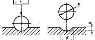
The depth is calculated as the difference in the thickness of the workpiece before (D) and after (d) processing. For longitudinal work: t = (D – d) : 2; and for transverse ones: t = D – d.
The permissible feed is determined in stages:
- numbers that provide the required surface quality, Shar;
- feed taking into account the characteristics of the tool, Sp;
- parameter value that takes into account the details of the part fastening, Sdet.
Each number is calculated using the appropriate formulas. The smallest of the obtained S is chosen as the actual feed. There is also a general formula that takes into account the geometry of the cutter, the specified requirements for the depth and quality of turning.
- S = (Cs*R y *ru) : (tx *φ z2), mm/rev;
- where Cs is the parametric characteristic of the material;
- R y – specified roughness, µm;
- ru – radius at the tip of the turning tool, mm;
- tx – turning depth, mm;
- φ z – angle at the tip of the cutter.
The spindle rotation speed parameters are calculated according to various dependencies. One of the fundamental ones:
v = (Cv*Kv) : (T m *tx *S y ), m/min, where
- Cv is a complex coefficient that generalizes the material of the part, cutter, and process conditions;
- Kv – additional coefficient characterizing the features of turning;
- T m – tool life, min;
- tx – cutting depth, mm;
- S y – feed, mm/rev.
Under simplified conditions and for the purpose of accessibility of calculations, the speed of turning a workpiece can be determined:
Read also: Sprocket chains for chain drives
V = (π*D*n) : 1000, m/min, where
- n – machine spindle rotation speed, rpm.
Equipment power used:
N = (P*v) : (60*100), kW, where
- where P – cutting force, N;
- v – speed, m/min.
The given method is very labor-intensive. There is a wide variety of formulas of varying complexity. Most often, it is difficult to select the right ones in order to calculate the cutting conditions during turning. An example of the most universal of them is given here.
Types of lathes
For each specific part, one or another unit is used:
- screw-cutting and turning: a group of machines that are in greatest demand in the manufacture of cylindrical parts from ferrous and non-ferrous metals;
- rotary-turning: types of units used for turning parts. Especially large diameters from metal blanks;
- lobe lathe: allows you to turn parts of cylindrical and conical shapes with non-standard dimensions of the workpiece;
- turret-turning group: production of a part, the workpiece of which is presented in the form of a calibrated pond;
- CNC - numerical control: a new type of equipment that allows you to process various materials with maximum precision. Experts can achieve this using computer adjustment of technical parameters. Turning occurs with an accuracy of micron fractions of a millimeter, which cannot be seen or verified with the naked eye.
Selection of cutting modes
Graphic-analytical and machine methods
The graphical method is auxiliary and is based on mathematical calculations. The calculated feed results are plotted on a graph, where the lines of the machine and cutter are drawn and additional elements are determined from them. This method is a very complex complex procedure, which is inconvenient for mass production.
The machine method is an accurate and affordable option for experienced and novice turners, designed to calculate cutting conditions during turning. The program provides the most accurate values in accordance with the specified initial data. They must include:
- Coefficients characterizing the material of the workpiece.
- Indicators corresponding to the characteristics of tool metal.
- Geometric parameters of turning tools.
- Numerical description of the machine and methods of securing the workpiece on it.
- Parametric properties of the processed object.
Difficulties may arise at the stage of numerical description of the source data. By setting them correctly, you can quickly obtain a comprehensive and accurate calculation of cutting conditions during turning. The program may contain inaccuracies, but they are less significant than with the manual mathematical version.
The cutting mode during turning is an important calculated characteristic that determines its results. Tools and cooling and lubricants are selected simultaneously with the elements. A complete rational selection of this complex is an indicator of the specialist’s experience or perseverance.
The main elements of the cutting mode include depth, feed and cutting speed. Let's consider the cutting scheme for turning using the example of turning a cylindrical surface on a lathe.
Additional materials
During manufacturing, most specialists are guided by the following indicators as an additional guide. Strength coefficient table:
| Workpiece material | Strength limit | Brinell hardness scale | Coefficient, MPa |
| alloy and carbon steel | varies from 400–1100 units | – | 1500–2600 |
| cast iron and also gray | – | 1400–2200 | 1000–1200 |
| bronze | – | – | 600 |
| silumin | – | – | 450 |
| duralumin | tensile strength from 250 to 350, but often higher depending on the quality of the workpiece | – | 600–1100 |
Material strength coefficient:
| Steel, kg/mm | Indicator value |
| 50,1–60,1 | 1,61 |
| 60,1–70,3 | 1,27 |
| 70,3–80,1 | 1,1 |
| 80,3–90,1 | 0,87 |
| 90,3–100,1 | 0,73 |
| Cast iron, kg/mm | Indicator value |
| 140,1–160,3 | 1,50 |
| 160,1–180,1 | 1,21 |
| 180,1–200,3 | 1,1 |
| 200,3–220,3 | 0,83 |
Cutter life coefficient:
| Duration value, minutes | Index |
| 27–30 | 1,27 |
| 43–46 | 1,11 |
| 57–60 | 1,09 |
| 83–90 | 1,03 |
Depth of cut
t – cutting depth, the amount of metal layer removed, measured perpendicular to the machined surface and removed in one pass of the cutting tool:
where Dzag – diameter of the treated surface, mm;
d – diameter of the treated surface, mm;
The depth of cut t is usually assumed to be equal to the allowance. During the finishing pass, t should be no more than 1…2 mm.
Figure 4.1 – Cutting elements and geometry of the cut layer