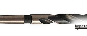
Rice. 2. Twist drill
The production of twist drills is carried out in specialized workshops or factories in large-scale or mass production. Therefore, despite the complex design, the cost of these drills is low.
The main structural elements and geometric parameters of twist drills are shown in Fig. 2. On the conical cutting part with an angle of 2φ at the apex there are two main cutting edges - the lines of intersection of the helical front and rear surfaces. The shape of the back surfaces is determined by the sharpening method. As a result of the intersection of two rear surfaces, a transverse cutting edge is formed, inclined to the main cutting edge at an angle ψ. This edge is located on the core of the drill with a nominal diameter d = (0.15. 0.25)d, where d is the diameter of the drill. Two auxiliary cutting edges lie at the intersection of the front surfaces and the cylindrical calibrating bands that guide the drill in the hole and form the calibrating part of the drill. The angle of inclination of the auxiliary edges to the drill axis ω determines mainly the value of the rake angles γ on the main cutting edges, which, as will be shown below, are variable in magnitude at different points of these edges.
To reduce the friction of the calibrating tapes on the walls of the hole, their width, depending on the diameter of the drill, is taken ƒ = (0.32. 0.45) d 0.5, and the height Δ = 0.1. 0.3 mm. To avoid pinching the drill in the hole, its diameter is reduced towards the shank - a reverse taper of 0.03. 0.12 mm per 100 mm length of the working part. In order to increase its strength and rigidity, the core of the drill is provided with a straight taper, i.e. the increase in its diameter towards the shank is equal to 1.4. 1.7 mm per 100 mm length.
The cutting and calibrating parts of the drill make up its working part, along the length of which drills are divided into short, medium and long series. Standard twist drills are made with a diameter of 0.1. 80 mm with tolerances according to A8. A9. The working part of the grinder is followed by a neck, which is used to mark the drill: diameter, material of the cutting part, and the manufacturer’s trademark.
Shanks are of two types: conical (Morse type) with a claw at the end for drills d = 6.80 mm and cylindrical for drills d = = 0.1. 20 mm. For drills d > 8 mm, the shanks are made of structural steel 45 or 40X, welded to the working part. To increase the friction force at the point of fastening the drill in the chuck and the possibility of straightening the drills along the length, the shanks are not thermally treated. The drill legs are hardened for hardening, as they are used to knock drills out of the machine spindle hole or from the adapter sleeve.
Geometric parameters of twist drills
. Twist drills have a complex geometry of the cutting part, which is explained by the presence of a large number of edges and complex front and rear surfaces. The geometric parameters of the twist drill are discussed below.
The vertex angle is 2φ, which plays the role of the main angle in the plan. For standard drills, 2φ = 116. 120°. In this case, the main cutting edges are strictly straight and coincide with the ruled generatrix of the helical front surface. When sharpening drills, the sharpening angle (2φzat ≠ 2φ) can be changed in the range from 70° to 135°. In this case, the cutting edges become curved, the ratio of the width and thickness of the cut chips and the size of the rake angles on the main cutting edges change. Accordingly, the degree of deformation of the cut allowance, the cutting forces and temperature, and the conditions for chip removal change.
Based on production experience, the optimal value of the angle 2φ is recommended to be taken depending on the material being processed, for example, when processing structural steels 2φ = 116.120°, corrosion-resistant and high-strength steels 2φ = 125.150°, cast iron, bronze 2φ = 90.100 °, high-hardness cast iron 2φ = 120.125°, non-ferrous metals (aluminum alloys, brass, copper) 2φ = 125.140°.
The clearance angle α on the main cutting edges is created by sharpening the drill feathers along the flank surfaces, which can be shaped as part of a flat, conical or helical surface.
Parts and elements of a twist drill.
Fig.21. Parts and elements of a twist drill.
1 - working part; 2 - cutting part; 3 - guide part; 4 - neck;
5 - shank; 6 - foot
The cutting part is the part of the drill sharpened to a cone. The working part is the part of the drill equipped with two spiral grooves. The guide is the part of the drill that guides the drill during the cutting process. The shank is the part of the drill that serves to secure the drill.
Fig.22. Main elements of the working part of the drill
1 - front surface; 2 - rear surface; 3 - cutting edge;
4 — ribbon; 5 - transverse edge
The rake surface is the helical surface of the groove along which the chips flow. Rear surface - the surface facing the cutting surface. Cutting edge - the line formed by the intersection of the front and rear surfaces; The drill has two cutting edges. Ribbon - a narrow strip on the cylindrical surface of the drill, located along the helical groove; Provides direction to the drill when cutting. Cross edge is the line formed by the intersection of both back surfaces.
Geometry of a twist drill.
The geometric parameters of the twist drill are shown in Fig. 23.
Fig.23. Geometry of a twist drill.
The angle 2φ (twice the entering angle) between the cutting edges varies widely depending on the material being processed. The inclination angle of the helical groove ω determines the rake angle and ranges from 100 to 45° depending on the material being processed.
Angle ψ - the angle of inclination of the transverse cutting edge is measured between the projections of the transverse and main cutting edges onto a plane perpendicular to the axis of the drill.
To determine the geometric parameters of the cutting edges, they are considered
1) in plane NN, perpendicular to the cutting edge;
2) in the OO plane, parallel to the drill axis. The front angle γ is considered in the NN plane.
The inclination angle of the helical groove ω and the clearance angle α are considered in
Cutting elements when drilling.
Classification of drills [edit | edit code ]
According to the design of the working part
there are:
- Spiral (screw)
drills are the most common drills, with a drill diameter from 0.1 to 80 mm and a working part length of up to 275 mm, widely used for drilling various materials.
- Zhirov’s designs
- on the cutting part there are three cones with angles at the apex: 2φ=116...118°; 2φ=70°; 2φ ' =55°. This increases the length of the cutting edge and improves heat dissipation conditions. A groove 0.15D wide and deep is cut into the jumper. The jumper is sharpened at an angle of 25° to the axis of the drill in a section of 1/3 of the length of the cutting edge. As a result, a positive angle γ≈5° is formed.
- Flat
(
feather
; jargon:
perki
) - used when drilling holes of large diameters and depths. The cutting part has the form of a plate (blade), which is mounted in a holder or boring bar or is integral with the shank. - Forstner drills
are an improved version of a feather drill, with additional cutters. - For deep drilling (L≥5D)
- elongated screw drills with two screw channels for internal coolant supply. Screw channels pass through the body of the drill or through tubes soldered into grooves milled into the back of the drill. - The designs of Yudovin and Masarnovsky
are distinguished by a large angle of inclination and the shape of the helical groove (ω=50...65°). There is no need to frequently remove the drill from the hole to remove chips, thereby increasing productivity. - Single-sided cutting
- used to make precise holes due to the presence of a guide (support) surface (the cutting edges are located on one side of the drill axis). - Cannon blades
are a rod whose front end is cut in half and forms a channel for removing chips. To guide the drill, a hole must first be drilled to a depth of 0.5...0.8D. - Gun
- used for drilling deep holes. They are made from a tube, which, when crimped, produces a straight groove for removing chips with an angle of 110...120° and a cavity for supplying coolant. - Hollow
(also annular, core) - drills that turn only a narrow annular part of the material into chips. - Centering
- used for drilling center holes in parts. - Stepped
- for drilling holes of different diameters in sheet materials with one drill. - with cylindrical shank (GOST 10902-77, DIN 338)
- with tapered shank (GOST 10903-77 (Morse taper), DIN 345)
- with three-, four- and hexagonal shank
- SDS, SDS+, etc.
By manufacturing method
there are:
- Solid
- spiral drills made of high-speed steel grades R9, R18, R9K15, R6M5, R6M5K5, or carbide. - Welded
- twist drills with a diameter of more than 20 mm are often made welded (the tail part is made of carbon and the working part is made of high-speed steel). - Equipped with carbide inserts
- available with straight, oblique and helical grooves (including ω=60° for deep drilling). - With replaceable carbide inserts
- also called cased (the mandrel to which the inserts are attached is called the body). Mainly used for drilling holes of 12 mm or more. - With replaceable carbide heads
- an alternative to case drills.
Read also: How to distinguish metric threads from inch threads
By purpose [edit | edit code ]
According to the shape of the holes being machined
there are:
According to the processed material
there are:
- Universal
- For processing metals and alloys
- For processing concrete, brick, stone
- it has a carbide tip designed for drilling hard materials (brick, concrete) with rotary impact drilling. Drills designed for a conventional drill have a cylindrical shank. The drill shank for rotary hammers has different configurations: cylindrical shank, SDS-plus, SDS-top, SDS-max, etc. - For processing glass, ceramics
- For wood processing
Geometry and elements of cylindrical metal drills
Cylindrical metal drill: main types and scope of application. Design features and main elements of twist drills: working part, shank, neck. Shank types: cylindrical and conical. Applicable GOSTs.
The metal cylindrical drill is the most well-known tool for making holes. The history of devices dates back to 1867, when the American Morse company presented the first tool at the World Trade Exhibition. To this day, the design of cylindrical drills has remained virtually unchanged - the main changes relate to the structural materials used.
In this article we will look at a variety of screw-type drilling devices that are used to make through and blind holes in metal products.
Elements and geometry of a twist drill
Processing of workpieces on drilling machines is carried out with drills, countersinks, reamers, taps and combined tools.
Drills according to their design are divided into spiral, centering and special. The most widely used are twist drills (Fig. 22.12), consisting of working part b, neck 2, shank 4 and leg 3. “The purpose of the shank is to secure the drill in the spindle. The foot serves to knock the drill out of the spindle and protect the shank from nicks. The working part consists of 1 cutting and 5 guide parts. To avoid pinching the drill, a reverse cone is made on it towards the shank. On the cutting part there are two main cutting edges 11 (formed by the intersection of the front 10 and rear 7 surfaces and performing the main cutting work), a transverse cutting edge 12 (jumper) and two auxiliary cutting edges 9. On the cylindrical part of the drill along the helical groove there are two narrow ribbons 8, ensuring the direction of the drill when cutting.
The geometric parameters of the drill determine its operating conditions. The front angle y is measured in the main cutting plane
| 1 2 3 Fig. 22.12. Parts, elements and angles of a twist drill |
II—II, perpendicular to the main cutting edge. The clearance angle a is measured in the I-I plane parallel to the drill axis. The front and rear corners at different points of the main cutting edge are different. At the outer surface of the drill, angle y is the largest, and angle a is the smallest.
The angle at the tip of the drill 2F is measured between the main cutting edges. Its value depends on the material being processed and varies within 70...150°.
The inclination angle of the transverse cutting edge y is measured between the projections of the main and transverse cutting edges onto a plane perpendicular to the axis of the drill. For standard drills it ranges from 50...55°.
The inclination angle of the helical groove c is measured along the outer diameter. As the angle increases, the rake angle y increases, which facilitates the cutting process and chip release. The angle ω is 8...30°.
Holes with a diameter of up to 80 mm are processed by drilling, and holes with a diameter of up to 30 mm are drilled, and larger ones are drilled out. Drilling is used as a preliminary treatment in the production of precise holes.
Countersinks (Fig. 22.13, a-c) process holes in cast or stamped workpieces, as well as pre-drilled holes. Unlike drills, countersinks have three or four main cutting edges and no cross edge. Cutting part 1 performs the main cutting work. The calibrating part 5 serves to guide the countersink in the hole and provides the necessary accuracy and surface roughness (the rest of the symbols are the same as for the drill).
| a 1 2 z b |
| Rice. 22.13.Tools for processing holes on drilling machines: a-c—countersinks; g-f—scans; f— tap |
According to the type of holes being machined, countersinks are divided into cylindrical (Fig. 22.13, a), conical (Fig. 22.13, b) and end (Fig. 22.13, c). Countersinks are either solid with a conical shank (Fig. 22.13, b) or mounted (Fig. 22.13, c). Holes with a diameter of 20...40 mm are processed with countersinks, and holes over 30 mm with mounted countersinks.
The final processing of the hole is carried out using reamers. Based on the shape of the hole being processed, cylindrical (Fig. 22.13, d) and conical (Fig. 22.13, e) reamers are distinguished. The reamers have 6...12 main cutting edges located on the cutting part 7 with a guide cone. The calibrating part 8 directs the reamer in the hole and ensures the necessary accuracy and surface roughness.
According to the mounting design, reamers are divided into tail (Fig. 22.13, d, e) and mounted (Fig. 22.13, f).
Taps are used for cutting internal threads. The tap is a screw with cut straight or helical grooves that form cutting edges (Fig. 22.13, g). The tap consists of 9 cutting and 10 calibrating parts. The thread profile of the tap must match the profile of the thread being cut.
Characteristics and purpose of cylindrical drills
Cylindrical drills are also known by other names: they are also called twist or screw.
Modern products differ in the following parameters:
- Material used. Professional tools are made of high-speed steel. The most popular variety among domestic producers is the P6M5 variety. It is valued for its good strength and wear resistance: drills made from this material hold an edge well and do not lose performance even when exposed to high temperatures.
- Method for obtaining a profile. To improve the accuracy of the tool, the grinding method is used. In addition, this approach allows you to extend the service life of the device.
- Availability of additional sharpening. The drill tip is subjected to additional processing. The method is used in the production of professional series products to increase alignment and reduce load during operation.
- Maximum hole diameter. In the largest specimens this figure can reach 80 mm.
The production of cylindrical drills for metal is carried out under mass production conditions. Finished products are subject to increased requirements, which are regulated by various interstate standards. Despite this, the cost of metal drills is low.
The geometry of twist drills has remained virtually unchanged since the first copies were released. It is thanks to the well-thought-out design of the working part that the device has become widespread.
- Screw channels provide good drainage of drilling by-products.
- The sharp angle between the tangent and cutting edges makes the work easier.
- A cylindrical metal drill is a reusable tool: it can withstand a large number of sharpenings, which are done manually or using machines.
- There are special ribbons on the outer surface of the calibrating part: they provide a stable direction of movement in the hole.
Elements of a twist drill [edit | edit code ]
A twist drill is a cylindrical rod, the working part of which is equipped with two (less often four) helical spiral grooves designed to remove chips and form cutting elements - ribbons.
- Working part
- The cutting part
has two main cutting edges formed by the intersection of the front helical surfaces of the grooves along which chips flow with the rear surfaces, as well as a transverse cutting edge (jumper) formed by the intersection of the rear surfaces. - The guide part
has two auxiliary cutting edges formed by the intersection of the front surfaces with the surface
of the strip
(a narrow strip on the cylindrical surface of the drill, located along the helical groove and ensuring the direction of the drill during cutting, as well as reducing friction of the side surface against the walls of the hole).
- for securing the drill to a machine or hand tool.
for transmitting torque to the drill or
a foot
for knocking the drill out of the conical socket.
, which ensures the exit of the wheel when grinding the working part of the drill.
Drill angles [ edit | edit code ]
- Point angle 2φ
is the angle between the main cutting edges of the drill. As 2φ decreases, the length of the cutting edge of the drill increases, which leads to improved heat dissipation conditions and, thus, increased durability of the drill. But with a small 2φ, the strength of the drill decreases, so its value depends on the material being processed. For soft metals 2φ=80…90°. For steels and cast irons 2φ=116…118°. For very hard metals 2φ=130…140°. - The angle of inclination of the helical groove ω
is the angle between the axis of the drill and the tangent to the helical line of the ribbon. The greater the inclination of the grooves, the better the removal of chips, but the less rigidity of the drill and the strength of the cutting edges, since the volume of the groove increases along the length of the working part of the drill. The value of the inclination angle depends on the material being processed and the diameter of the drill (the smaller the diameter, the smaller ω). - The rake angle γ
is determined in a plane perpendicular to the cutting edge, and its value changes. It has the greatest value at the outer surface of the drill, the smallest at the transverse edge. - The clearance angle α
is determined in a plane parallel to the drill axis. Its values, like the front angle, change. Only it has the greatest value at the transverse edge, and the smallest at the outer surface of the drill. - The inclination angle of the transverse edge ψ
is located between the projections of the main and transverse cutting edges onto a plane perpendicular to the drill axis. For standard drills ψ=50…55°.
Variable values of the angles γ and α create unequal cutting conditions at different points of the cutting edge.
Drill angles during cutting [edit | edit code ]
The angles of the drill during the cutting process differ from the angles in the static state, just like those of the cutters. The cutting plane in kinematics turns out to be rotated relative to the cutting plane in statics by an angle μ, and the actual angles during the cutting process will be as follows:
Design Features
- Working part. Consists of two spiral (screw) channels. Their intersection forms the cutting part. The channels provide the supply of coolant to the drilling zone and are responsible for removing chips during the work process.
- Shank. This part is fixed in the chuck of the working equipment. There are two types of shanks: conical (Morse type) with a claw at the end and cylindrical.
The shank is not subjected to heat treatment. This is necessary to increase the friction force in the chuck and the possibility of straightening to length. For tools with a working part diameter over 8 mm, the main shank material is structural steel type 40X. This element is a separate unit, which is subsequently welded to the working part of the product. In this case, the drill legs are hardened to increase strength, since they are used to knock the tool out of the spindle or adapter sleeve.
- Neck. Here you can find the tool marking: working diameter, type of material, as well as information about the manufacturer.
Twist drills
Twist drills are the most common. This drill (Fig. 309) consists of a working part, including a cutting part, a neck, a conical one ( Fig. 309, a
) or a cylindrical (
Fig. 309, b
) shank for fastening the drill in the spindle of the machine, a foot that serves as a stop for knocking the drill out of the spindle socket.
The cutting part ( Fig. 309, c
) consists of two teeth formed by two grooves for removing chips; core - the middle part of the drill connecting both teeth; two front surfaces along which chips run and which absorb the cutting force; two ribbons - narrow strips along the outer diameter of the drill, serving to guide and center it in the hole; two main cutting blades formed by the intersection of the front and rear surfaces and performing the main cutting work; a transverse blade or bridge formed by the intersection of both rear surfaces.
Rice. 309.
Elements, geometric parameters and sharpening of twist drills: 1 and 10 - ribbon blades; 2 and 6 — ribbons; 3 - two cutting blades; 4 and 8 — backs at the teeth; 5 - grooves; 7 - transverse blade; 9 - front surface.
A twist drill contains five blades: two main, two auxiliary (along the ribbons) and a transverse one, which does not cut, but crushes and squeezes out the metal. The cross blade of the drill has its main defect. The geometric parameters of the drill are considered on its cutting part.
The rear angle α is considered in the plane AA, parallel to the axis of the drill (Fig. 309, d), for the current point x (see section AA); it changes from αmin at the peripheral point of the drill to αmax, at the drill bridge.
The rake angle γ is taken in the plane BB, perpendicular to the cutting blade of the drill ( Fig. 309, d
), for the current point x; this angle changes from γmin at the drill bridge to γmax at the peripheral point of the drill. The angle at the tip of the drill 2φ is between the main cutting blades: 2φ = 116 ÷ 118° when processing steel, cast iron, hard bronze; 2φ = 140° when processing aluminum and light alloys; 2φ = 80 ÷ 90° when processing ebonite, celluloid, marble.
The angle of inclination of the transverse blade ψ is 55º.
Drill sharpening . By sharpening the drill (Fig. 309, d) the following angle values are given: αmin ≈ 7º, αmax ≈ 26º, γmin ≈ 3º, γmax ≈ 30º.
The criterion for correct sharpening is compliance with the angles 2φ, ψ and αmin.
In addition, it is necessary that the axis of the drill passes through the middle of the jumper and divides the apex angle of 2φ into two equal parts and that the main cutting blades are equal. To avoid pinching the drill on the drill, give a reverse cone towards the shank by an amount of approximately 0.05 mm per 100 mm length.
In Fig. 309, d
single sharpening of the drill is given;
in Fig.
309, e - double sharpening of the drill;
in Fig.
309, g - single sharpening with sharpening of the transverse blade;
in Fig.
309, h - single sharpening of the drill with sharpening of the ribbons. Double sharpening of the drill increases the durability of the drills, sharpening the jumper and ribbons facilitates the drilling process, reduces friction, and reduces the amount of feed force. With double sharpening there are angles 2φ and 2φ0; at 2φ = 116 - 118º, 2φ0 = 70 - 75°.
A bridgeless twist drill was proposed by the innovator V.I. Zhirov. Such drills are obtained from standard drills by using their special sharpening.
In the transverse blade ( Fig. 310, c
) drills cut a groove with a grinding wheel, which significantly reduces the feed force.
Rice. 310.
Bridgeless twist drill designed by V.I. Zhirov.
However, the best results (increased productivity and increased durability) are provided by a combined sharpening of the transverse drill blade ( Fig. 310, b
). Here, at a distance K equal to one third of the length of the cutting blade, the transverse blade is sharpened with an undercut of its core at an angle of 30°. The width of the cut groove a and the depth h are equal to 0.15 of the drill diameter.
It is necessary to ensure that sharpening is done efficiently. It is especially recommended to take drills with a double cone ( Fig. 310, a
).