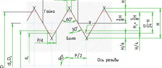
CNC machines often perform thread cutting with a tool with replaceable inserts. The inserts can be designed for cutting different types of connections (for example, inch, metric and others). The ratio parameters have a direct relationship with the size of the thread being cut.
The total cutting depth is divided into several passes. This increases the reliability of the workflow. These measures ensure that the upper part of the threaded plate is resistant to overload. To perform profile threading, most often, a turner performs 6 passes on the machine.
Specifics of thread formation
Turning technology:
- An effective way to obtain threads.
- Suitable for forming screw connections of any profile.
- A simple processing technique that has been thoroughly studied.
- High surface quality after the event.
- Cutting on CNC machines occurs using standard cycles.
- The task can be completed in a deep hole if vibration-preventing mandrels are integrated into the workflow.
engineer will help - Thread cutting on a CNC machine
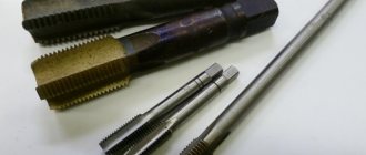
The most common tools for producing internal threads on CNC machines are taps and cutters. The difficulty of producing threads using a milling cutter is associated with the complexity of programming the interpolating movement, so the simpler the CNC system, the more often taps are used.
When milling, the thread profile is formed by moving a special cutter along a helical line. The feed in this case must coincide with the pitch of the tap.
Technology for producing threads by milling
Drill a hole
The thread cutter is lowered into the hole to the desired thread depth and cuts in a 90° arc to the depth. When cutting in, the cutter rises by ¼ of the thread pitch (section 1-2).
The axis of the cutter M makes a revolution at diameter m (section 2-3), while the cutter simultaneously rises by thread pitch P and exits the profile along an arc of 90° (section 3-4).
If the depth of the thread in the previously obtained hole is greater than the length of the cutting part of the cutter, then the processing in section 2-3 is repeated several times.
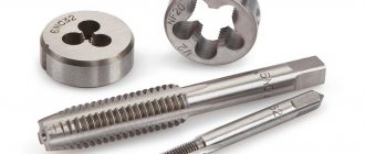
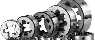
There are several types of thread cutters used for cutting threads on CNC machines.
carbide cutters thread cutters with replaceable inserts combined thread cutters are cutters that allow you to first drill a hole for a thread and then mill the thread
Therefore, there are 2 main technologies for producing threads using cutters
Making threads with one tool
Making threads with multiple cutting tools
Straight flute taps
The straight flute tap is the most widely used type of tap. This tap is used for materials that produce short chips, such as steel or cast iron.
Checkered tooth taps
Using a tap with a staggered tooth reduces friction and resistance to the cutting process, which is very important when processing difficult-to-cut materials (aluminum and bronze). The staggered arrangement of the teeth on the tap facilitates coolant access to the cutting zone.
Spiral point taps
A spiral point tap has straight, shallow chip flutes. The spiral point is designed to push the chips forward. Relatively shallow chip flutes guarantee maximum torsional strength of the tap. They also facilitate the supply of coolant to the cutting zone. This type of tap is recommended for machining through holes.
Taps with flutes on the fence part only
The cutting part of this tap has a similar spiral point designed to push chips forward. This tap has an extremely rigid design. Recommended for machining holes up to 1.5 x 0 in depth.
Spiral tooth taps
Spiral tooth taps are primarily designed for cutting threads in blind holes. The spiral flute pushes chips back, which prevents chips from packing at the bottom of the hole or in the flutes. Therefore, the spiral groove of the tap reduces the risk of breakage or damage to the tap.
Chipless taps (rollers)
Chipless taps differ from conventional taps in that they form a thread profile due to plastic deformation, and not due to chip removal. Recommended for materials with high ductility. Such materials have a tensile strength of no more than 1200 N/mmg, and a relative elongation of at least 10%.
Chipless taps can be used under normal conditions, but they show best results when machining vertical blind holes. Also available with internal coolant supply.
Thread milling cutters have a huge advantage when machining blind holes. The tap always needs clearance between the bottom of the hole and the end of the tap due to the taper taper. Therefore, the tap does not cut a thread in a blind hole. Using a cutter will solve this problem, since the distance from the end of the cutter to the first cutting threaded edge is very small. Another big advantage of thread cutters is the ability to change thread parameters, which is not possible when using a tap. This feature significantly reduces threading costs.
Remember that the feed is equal to the spindle revolutions multiplied by the thread pitch when working with a tap. The thread can be cut off when the spindle stops before reversing - the Z axis has already stopped, but the spindle, due to inertia, still makes some part of the revolution.
When cutting a thread with a tap in steel, the tap breaks off, but the D16T is softer and therefore licks off the thread. Therefore, to cut threads on a CNC machine, you need to use a special chuck - a floating chuck, or it is also called a compensating chuck.
This cartridge has a spring-loaded part with a collet, which can move relative to the stationary one by several millimeters along the axis of the cartridge in both directions.
Here are general instructions for cutting threads with taps
The outcome of any thread cutting operation depends on a number of factors, each of which ultimately affects the quality of the finished part.
1. Select the correct tap design for the material being processed and the hole type.
2. Make sure that the part is securely fastened - movements during processing can lead to breakage of the tap or poor thread quality.
3. Select the correct drill size from the corresponding tables. The diameter of the required drill is also indicated on the pages of the catalog with taps. Remember that rolling taps require drills of other diameters. Always check the work hardening of the material being processed.
4. Select the correct cutting speed as shown in the cutting tap catalogue.
5. Use coolant appropriate for the operation being performed.
6. When cutting threads on CNC machines, check the feed value specified in the program. When using a tapping chuck, the feed per revolution should be 95 to 97% of the pitch to self-tighten the tap.
Thread milling technology:
- Milling is carried out in stationary parts that do not rotate during processing.
- Wide possibilities in the field of machining parts with long overhangs or thin walls are opened up due to the rather low cutting force.
- A screw connection can be created flush against a shoulder or the bottom of a hole and requires a groove to guide the tool out.
Thread milling of parts with large dimensions, which makes it impossible to install them on turning equipment. Milling allows you to form a profile in one pass thanks to the movement of the tool along helical interpolation.
Thread milling.
General information. Thread milling is used in the production of large parts, large-diameter threads, large pitches, multi-start and long threads, threads crossed with keyways or flats, as well as threads on thin-walled parts. In mass production, thread milling produces conventional cylindrical or conical threads of 2-3 accuracy classes.
There are two methods of milling threads: disk (single-thread) and comb (multi-thread) thread milling cutters (Fig. 1 and 2.).
Fig.1. Milling external threads with a disk cutter.
Fig. 2. Milling cylindrical threads with a comb cutter: a-external right-hand thread; b-internal right-hand thread.
The axes of the workpiece and the disk cutter, intersecting at the angle of the thread, can lie in parallel or intersecting planes (Fig. 3.). The axes of the workpiece being milled and the comb cutter lie in the same plane, being parallel or intersecting (Fig. 2 and 4).
Fig.3. Disc cutter location diagram: a-with an axis parallel in the horizontal plane to the axis of the thread being cut; b-with an axis inclined in a horizontal plane.
Fig.4. Milling of conical threads with a comb cutter: a-conical; b-cylindrical.
Milling of external threads is carried out using the rounding or enveloping method.
Thread milling is also done with solid or prefabricated milling cutters - heads equipped with carbide. The last milling method is called vortex milling.
The diagram of vortex milling of external threads using the wrapping method is shown in Fig. 5.a. and by the bending method - in Fig. 5.b.
Fig.5. High-speed milling of: a-external threads using the wrapping method; b-external thread by bending method; in-female thread.
Milling of internal threads using this method is carried out using a single-cut head (Fig. 5.c.) or a multi-tooth cutter.
External thread milling can be done with a specially profiled end mill with cutters reinforced with carbide (Fig. 6.). To mill short threads, the axis of the cutter can be perpendicular to the axis of the workpiece being cut.
Fig.6. Milling external threads with an end mill.
Multi-start threads are milled with both disc and comb cutters. In the first case, the entries are milled sequentially by division, and in the second - continuously. In both cases, the feed per revolution of the workpiece is equal to the stroke (step Χ number of starts) of the thread. The length of the comb cutter must be greater than the length of the milled thread by an amount that is a multiple of the pitch (stroke) of the thread.
Thread milling with comb cutters is carried out on simple or planetary machines.
Simple thread milling machines are used for milling external or internal threads on rotating workpieces, while planetary type machines are used for large or bulky workpieces that are difficult to rotate.
Similar articles:
- To obtain the largest possible number of teeth and the best geometry, disc cutters are manufactured with sharply sharpened teeth. Disc cutters with variably cut (beveled) teeth are widely used for thread milling. Such cutters create favorable cutting conditions due to...
">Disk thread cutters
News archive:
- There are two types of heads - non-rotating and rotating. Non-rotating heads with tangential combs are not widespread in our industry. Rotating heads are used mainly on bolt cutting machines; they are used for cutting cylindrical and conical threads of the 2nd precision class...
">Screw-tapping heads with tangential combs
- There are three types of combs: with a straight, with a convex or concave occipital surface (Fig. 1.). The first two types of combs are obtained by milling or grinding threads with a straight feed or with a circular feed - in a special drum. In combs with a concave occipital surface of the thread...
">Prismatic dies for screw cutting heads
- There are two types of heads - non-rotating and rotating. Due to their small dimensions, the first type of heads is used on single-spindle machines. In terms of the number of permissible regrindings, prismatic combs are inferior to disk combs and therefore are less economical. Non-rotating heads type DS with...
">Screw-tapping heads with prismatic combs
- According to GOST, there are three types of screw-cutting (screw-cutting) heads: non-rotating, designed for use on turret and lathes (Fig. 1.); rotating, designed to work on bolt cutters, drilling machines and multi-spindle automatic lathes (Fig. 2.); special - d...
">Screw-tapping heads with disc combs
- Types of heads. Threading heads are used for cutting external and internal threads on drilling, aggregate, turret, bolt cutting machines and automatic machines. The combs are mounted in the body of the threading head, which at the end of the working cycle disengage with the workpiece being cut. IN…
">Cutting external and internal threads using threading heads
Next page >>
Daoist Yoga
Thread cutting cycle. Code G84.
This cycle provides a sequence of actions to ensure thread cutting. The current feedrate (F) and spindle speed (S) are used. The spindle is accelerated at a certain speed and fed along the Z axis. At the base of the hole, the spindle and Z-axis slow down for a coordinated stop. The direction is then reversed and the reverse process of the programmed increase in speed and feed begins.
In BNC, the G84 code is used for normal and left-hand threads. The spindle rotation commands are clockwise (M3) or counterclockwise (M4).
In ISNC, the G84 code only provides normal thread formation. Starting the spindle counterclockwise (M4) causes the spindle to return to the beginning of the cycle to ensure that the operation is completed.
The formula for calculating the feed rate for a thread cutting cycle is:
| Feed in mm or inches per minute | = | Spindle revolutions per minute |
| Number of turns per mm or per inch |
Important:
-When M3/M4 commands are detected in the program and the current tool in the spindle is determined in the tool settings, the system scans 10 blocks ahead to detect other threading cycles, G01/G02/G03 codes and non-threading canned cycles. If at least one machining move (G01, G02, G03) or any other canned cycle is found in this range, the spindle is turned on as usual. If a G84 code is found and all M3/M4 moves are rapid moves, then rapid moves will be executed in the spindle disable step
-The spindle rotates clockwise towards the base of the hole. At the base of the hole, the spindle completely changes direction of rotation and the tap (tool) exits, which means the end of the operation at a constant feed.
For ISNC, command (M29) initiates a rigid threading cycle instead of normal threading. Rigid tapping is disabled with G00, G01, G02, G03, or G80. The feed rate for the rigid tapping cycle can be adjusted.
Command format for thread cutting cycle:
G84 X ___, Y ___, Z ____, R ____, P ___, F ____, [K ___, or L]
Note : P is used for threading cycle only in ISNC standard. P determines the rotation delay period at the base of the hole and after exiting the hole. Q is an additional passage depth used only in the ISNC standard. If Q is equal to 0.0, then no pass processing occurs. Q is used with code G74 with M29 for rigid threading only.
Example: The diagram below illustrates the tool movement for a cycle (G84):
— Part - detail
-Z (Start, Bottom) – point (starting, base of the hole)
— At point Z Bottom, the spindle rotation stops with its time delay and the spindle reverses.
Figure 3-51. Movement of the tool through the thread cutting cycle. Code G84.
Boring. Code G85.
The boring cycle provides the sequence of tool entry and exit required for boring operations.
Movements under code G 85:
-The spindle must already be enabled by code M3.
-The tool is positioned above the hole location.
-According to the G85 code cycle, the spindle is fed along the Z axis to the base.
-Return to original Z state.
Note: It is possible to use G85 code to move the tool along the XY plane.
G85 command format: G85 X ___, Y ___, Z ___, R ___, F ___,
Example: The diagram below illustrates the tool movement through a G85 cycle:
— Part - detail
-Z (Start, Bottom) – point (starting, base of the hole)
Figure 3-52 Movement of the tool along the boring cycle. Code G85.