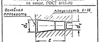
HOLES FOR TAPERED PIPE THREAD
DIAMETERS
GOST 21350-75
STATE COMMITTEE OF STANDARDS OF THE COUNCIL OF MINISTERS OF THE USSR
Moscow
DEVELOPED, INTRODUCED AND PREPARED FOR APPROVAL by the All-Union Scientific Research Institute for Normalization in Mechanical Engineering (VNIINMASH)
And about. Director Gerasimov N.N.
Topic leader and performer Zaroslova M.P.
APPROVED AND ENTERED INTO EFFECT by Resolution of the State Committee of Standards of the Council of Ministers of the USSR dated December 12, 1975 No. 3877
STATE STANDARD OF THE USSR UNION
| HOLES FOR TAPERED PIPE THREAD Diameters Holes for threading pipe taper screw thread. Diameters | GOST 21350-75 Instead of MN 5389-64 |
By Decree of the State Committee of Standards of the Council of Ministers of the USSR dated December 12, 1975 No. 3877, the validity period was established
from 01.01.77
1. This standard establishes the diameters of holes for cutting conical pipe threads in accordance with GOST 6211-69 in steel products in accordance with GOST 380-71, GOST 4543-71, GOST 1050-74, GOST 5058-75 and GOST 5632-72 (except for alloys on nickel base) and copper according to GOST 859-66.
2. The diameters of the holes with reaming to a cone and their maximum deviations must correspond to those indicated in the drawing. 1 and in table. 1.
Table 1
Dimensions in mm
| Number of threads per 1² | Step P | Hole diameter | Drilling depth l | d c | d o | Nom. | Prev. off | Nom. | Prev. off | 0,907 | 8,10 | 0,20 | 8,57 | 0,10 | 1,337 | 10,80 | 0,24 | 11,45 | 14,30 | 14,95 | 1,814 | 17,90 | 18,63 | 23,35 | 0,28 | 24,12 | 2,309 | 29,35 | 30,29 | 1 1/4 | 37,80 | 0,34 | 38,95 | 1 1/2 | 43,70 | 44,85 | 55,25 | 0,40 | 56,66 | |||||||||
Note. For threads with nominal size above 2 ² nominal hole diameters d
o and their maximum deviations must be equal to those established by GOST 6211-69 for the internal diameter of the thread.
3. The diameters of the holes without turning to a cone and their maximum deviations must correspond to those indicated in the drawing. 2 and in table. 2.
4. It is allowed to use holes of other diameters obtained on the basis of experimental data for cutting conical pipe threads.
5. The diameters of drills for holes for tapping are indicated in the recommended one.
table 2
Dimensions in mm
| Nominal thread size in inches | Number of threads per 1² | Step P | Hole diameter d c | Drilling depth l | Nom. | Prev. off | 1 / 8 | 0,907 | 8,25 | 0,20 | 1 / 4 | 1,337 | 11,05 | 0,24 | 3 / 8 | 14,50 | 1 / 2 | 1,814 | 18,10 | 0,28 | 3 / 4 | 23,60 | 2,309 | 29,65 | 1 1 / 4 | 38,30 | 0,34 | 1 1 /2 | 44,20 | 56,00 | 0,40 | Diameters of drills for holes for cutting conical pipe threads Dimensions in mm Nominal thread size in inches | Number of threads per 1² | Step P | Drill diameter for hole | with cone deployment | without cone deployment | 1 / 8 | 0,907 | 1 / 4 | 1,337 | 10,8 | 11,1 | 3 / 8 | 14,25 | 14,5 | 1 / 2 | 1,814 | 3 / 4 | 23,25 | 2,309 | 1 1 / 4 | 38,25 | 1 1 /2 | 56,00 | ||||||||
Making internal threads is usually not difficult. But there are some features of using the tool and selecting holes for cutting metric threads.
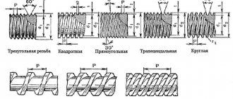
Types of thread
They differ in their main characteristics:
- diameter calculation system (inch, metric, others);
- number of passes (two-, three- or single-pass);
- profile shape (rectangular, trapezoidal, triangular, round);
- direction of rotation of the screw (left or right);
- placement on the part (internal or external);
- shape of the part (cone or cylinder);
- purpose (running, fastening and sealing or fastening).
According to the listed characteristics, the following types are distinguished:
- cylindrical (MJ);
- metric and conical (M, MK);
- pipe (G, R);
- Edison round (E);
- trapezoidal (Tr);
- round for plumbing fasteners (Kp);
- persistent (S, S45);
- inch, including cylindrical and conical (BSW, UTS, NPT);
- oil range.
Tools for internal threading
To make internal cutting, you need a tap - a screw-shaped tool with sharp grooves. The rod can be shaped like a cone or a cylinder. The grooves run lengthwise and break the thread into sections called combs. It is the edges of the combs that are the working surfaces.
To ensure a clean groove, the metal is removed gradually, in layers. This requires one very long tool or set.
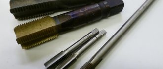
Single taps are also found on sale; they are often used to correct broken threads. To cut a new one, buy a kit. Therefore, taps are usually sold in pairs: for roughing and for finishing work. The first one cuts a shallow groove, the second one cleans and deepens it. There are also three-pass tools. Thin taps, up to 3 millimeters, are sold in twos, wider ones - in threes. Three-pass taps are inserted into the gates. The design of the knobs is different, but their size must match the size of the cutter.
The tools in the set are distinguished by the marks marked on the tail end. If you look closely, you will notice differences in shape:
- the first tap has heavily cut tooth tips, the outer diameter is slightly smaller than the other tools in the set;
- second tap with shorter fence segment, longer ridges. Its diameter is slightly larger than that of the first;
- the third tap has full ridges of teeth, and its diameter should match the dimensions of the future thread.
Taps are divided into pipe taps (marked “G”) for cutting threads inside the pipe, and metric taps, which are more common.
The quality directly depends on the properties of the tap: it must be made of good metal and sharp. To extend the life of the tool and improve the quality of the thread, lubricant is used. Usually, to acquire a stable cutting skill, you need to make 3 - 5 attempts.
Cutting process
Before you start cutting, you should use drills to make a hole in the workpiece. The diameter of the drill hole must match the internal thread size. When the size of the hole made with drills is chosen incorrectly, the tool can break or the grooves will turn out to be of poor quality.
During cutting, part of the metal does not fall out with chips, but is pressed along the working surfaces of the tap, forming a groove profile on the workpiece. Taking this feature into account, the size of the drill used to make the hole for the thread is selected slightly smaller than the nominal diameter of the future thread.
For example, when cutting M5 (groove diameter is 5 mm), you should choose a drill for a 4.2 mm hole. To cut M4, the diameter of the drill must be 3.3 millimeters, and before working with an M6 tap, a hole is first made with a 5 mm drill. This indicator is calculated taking into account the thread pitch. The pitch can be calculated mathematically, but in practice they resort to correspondence tables, where for an M5 tap the pitch is 0.8, for M4 this figure is 0.7, for M6 - 1. We subtract the pitch index from the diameter and get the required diameter of the drill. When working with brittle metals, such as cast iron, the drill diameter should be reduced by 0.1 mm compared to the size recommended in the table.
The formula for calculating the hole diameter when working with three-pass taps:
Up=Dm * 0.8
;
here: Dm is the diameter of the tap.
| Type | Diameter | Step |
| M1 | 0,75 | 0,25 |
| M1,2 | 0,95 | 0,25 |
| 1,4 | 1,1 | 0,3 |
| 1,7 | 1,3 | 0,36 |
| 2,6 | 1,6 | 0,4 |
| 2,8 | 1,9 | 0,4 |
| M3 | 2,1 | 0,46 |
| M3 | 2,5 | 0,5 |
| M4 | 3,3 | 0,7 |
| M5 | 4,1 | 0,8 |
| M6 | 4,9 | 1 |
| M8 | 6,7 | 1,25 |
| M10 | 8,4 | 1,5 |
Table 1. Correspondence between thread diameters and preparation hole
Before starting work, the tap is inserted into a square shank - a knob. The collars can be regular or ratchet. The carving is done carefully, the first pass is made with a No. 1 tap to the end. Particular attention must be paid to the direction of movement: only clockwise, and some effort must be applied. It is done like this: 1/2 turns along the stroke alternate with 1/4 turns against the screw stroke to destroy the chips.
| Thread in inches | External D, mm | Diameter, mm | Pitch, mm |
| 1\8″ | 2,095 | 0,74 | 1,058 |
| 1\4″ | 6,35 | 4,72 | 1,27 |
| 3\16″ | 4,762 | 3,47 | 1,058 |
| 5\16″ | 7,938 | 6,13 | 1,411 |
| 7\16″ | 11,112 | 8,79 | 1,814 |
| 3\8″ | 9,525 | 7,49 | 1,588 |
Table 2. Hole diameters for inch threads
A couple drops of lubricant will make working on blind threaded holes much easier. Although machine oil is sometimes used as a lubricant, drying oil is optimal for working with steel. With aluminum alloys, it is preferable to use kerosene, alcohol or turpentine. Technical oil can also be used, but with less effect.
Types
Characteristics
Everyone knows what a thread looks like - it is a sequence of helical grooves that have a constant pitch and cross-section. It can be applied to a cylindrical or conical surface.
As for pipes, cutting can be used in products for a wide variety of purposes to ensure dismountable installation of the pipeline. Most often it is found in domestic water supply and heating systems.
Types of diameters
Its main characteristics are the following indicators:
- Location;
- Unit of measurement of dimensions;
- Direction;
- Profile of thread-forming surface;
- Number of visits.
It should be noted that threaded pipe connections are a fairly separate group of standards, which are regulated by GOST 6357-81.
Schematic designation of pipe threads in the drawing
Inch
Inch threads are used on metal pipes, as well as metal and plastic collapsible pipe fittings. According to GOST, its main characteristics are pitch and diameter.
Moreover, this parameter can be understood as:
- The outer diameter is the distance between the upper opposite points located at the tops of the ridges.
- Internal - the distance between the lower opposite points located on the depressions of the grooves.
The difference in these parameters determines the profile height.
Cylindrical inch cutting
The pitch, as you might guess, is the distance between adjacent turns. This parameter is always the same throughout the entire threaded section. All dimensions in this case are indicated in inches.
The table below shows the pipe thread dimensions in mm:
| Diameter in inches | Outer diameter of pipe thread in millimeters | Step |
| 2 | 59,616 | 2,309 |
| 1 3/4 | 53,748 | |
| 1 1/2 | 47,805 | |
| 1 3/8 | 44,325 | |
| 1 1/4 | 41,912 | |
| 1 1/8 | 37,898 | |
| 1 | 33,250 |
In everyday life, pipes with the following types of cutting are most often used:
- With a pitch of 14 threads per inch: 3/4″ diameter;
- 1/2″.
11 threads per inch:
- diameter 1 1 – 4;
- 1″;
- 2″;
- 1 1/2″.
In the photo - an adapter from metric to inch cutting
Metric
The main characteristics of metric cutting are the same as those of inch cutting - diameter and distance between turns. But, in this case, what is the difference between metric thread and pipe thread?
In fact, there are very few differences, the main ones being the following:
- Ridge profile shape. The inch profile has a sharper profile.
- Metric dimensions are indicated in millimeters. True, for convenience, you can convert the pipe thread to mm.
- The pitch in the inch version is calculated not in mm, but in threads - the number of grooves that fit on an inch measuring segment. For example, in standard water pipes there are two “pitch” options: 11 threads (2.31 mm);
- for 14 threads – (1.8 mm).
Otherwise, pipe and metric threads are no different.
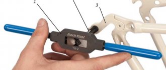
Thread gauge
Homemade tap for aluminum alloys
To create internal threads in brass or light alloy parts, you can use homemade tools and drills from a regular set. Calibrated steel wire will do. Using a die, an external thread is cut on it, after which the workpiece is hardened. After hardening, it is necessary to release the part to the color of ripe straw. The cutting edges are sharpened using a whetstone or sharpener, after first clamping the part into a collet chuck.
Video on how internal threads are cut:
To cut an internal thread on a part, you must first drill a hole. Its size is not equal to the thread diameter, but should be slightly smaller. You can find the diameter of the drill for the thread in a special table, but to do this you also need to know the type of thread.
Main settings
- diameter (D);
- pitch (P) - the distance from one turn to another.
They are determined by GOST 1973257-73. A large step is considered normal, but it corresponds to several smaller ones. A small pitch is used when applying to thin-walled products (pipes with a thin wall). They also make a small turn if the applied thread is a way to adjust any parameters. Also, a small step between turns is made to increase the tightness of the connection and to overcome the phenomenon of self-unscrewing of the part. In other cases, a standard (large) step is cut.
There are many types of threads, since each has its own formation characteristics; the diameter of the hole for the thread is different in each case. All of them are prescribed in GOST standards, but most often they use triangular metric and conical metric threads. We will talk about them further.
We usually see triangular threads on bolts and other similar fasteners, conical threads on most plumbing products that require a detachable connection.
Adaptations
To apply carvings with your own hands, use small devices:
All these devices are made of alloys characterized by increased strength and abrasion resistance. Grooves and grooves are applied to their surfaces, with the help of which their mirror image is obtained on the workpiece.
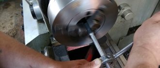
Any tap or die is marked - they have an inscription indicating the type of thread that this device cuts - diameter and pitch. They are inserted into holders - collars and die holders - and secured there with screws. Having clamped the thread cutting device in the holder, it is put on/inserted into the place where you want to make a detachable connection. By turning the device, turns are formed. How correctly the device is positioned at the beginning of work determines whether the turns will “lay down” evenly. Therefore, make the first revolutions, trying to keep the structure level, avoiding shifts and distortions. After a few turns, the process will become easier.
You can cut small or medium diameter threads by hand. Complex types (two- and three-way) or working with large diameters by hand are impossible - too much effort is required. For these purposes, special mechanized equipment is used - lathes with taps and dies attached to them.
How to cut correctly
Threads can be applied to almost any metals and their alloys - steel, copper, aluminum, cast iron, bronze, brass, etc. It is not recommended to do it on hot iron - it is too hard, it will crumble during operation and it will not be possible to achieve high-quality turns, which means the connection will be unreliable.
Tool for the job
Preparation
You need to work on clean metal - remove rust, sand and other contaminants. Then the place where the thread will be applied must be lubricated (except for cast iron and bronze - they must be worked “dry”). There is a special emulsion for lubrication, but if it is not there, you can use soaked soap. You can also use other lubricants:
You can often hear advice to use machine or mineral oil or even lard when cutting threads. They work well, but experts say that it is better not to do this - the chips will stick to the viscous substance, which will lead to rapid wear of the tap or die.
Slicing process
When cutting external threads, the die is placed strictly perpendicular to the surface of the pipe or rod. During operation, it should not wiggle, otherwise the turns will turn out uneven and the connection will be ugly and unreliable. The first turns are especially important. How they “lay down” determines whether the connection will then be skewed.
By applying the internal thread, the part is fixed motionless. If it is a small piece, you can clamp it in a vice. If the plate is large, ensure its immobility using available methods, for example, by fixing it with bars. M
The tap is inserted into the hole so that its axis is parallel to the axis of the hole. With little effort, little by little, they begin to twist in the given direction. As soon as you feel that the resistance has increased, unscrew the tap back and clear it of chips. After cleaning, the process continues.
Photo cutting process
When cutting a thread in a blind hole, its depth should be slightly greater than required - this excess should include the tip of the tap. If this is structurally impossible, the tip of the tap is cut off. At the same time, it is not suitable for further use, but there is no other way out.
In order for the turns to be of high quality, two taps or dies are used - rough and finishing. The first pass is done as a rough pass, the second as a finishing pass. There are also combined devices for applying threads. They allow you to do everything in one pass.
Another practical tip: to prevent chips from getting into the working area, when cutting, make one full turn clockwise, then half a turn counterclockwise. After this, return the tool to the place where you stopped and make one revolution again. Continue this way until the required length.
Water pipe diameter tables
One of the most important characteristics of a steel pipe is its diameter (D). Based on this parameter, all required calculations are made when designing an object. How to choose the diameter so as not to make a mistake?
The diameters of metal pipes are standardized and must correspond to the values of GOST 10704–91.
Conventionally, they are divided into several subgroups:
- Large – 508 mm and above,
- Medium – from 114 to 530 mm,
- Small – less than 114 mm.
Classification
When it is necessary to carry out plumbing, ordinary pipes are installed that can withstand a small load. In a private house, it is better to use welded metal water pipes. The cost of such products is somewhat lower than similar seamless ones. The technical characteristics and properties of such a product fully meet all the requirements for laying water pipes.
Main dimensions
Depending on this characteristic and its numerical value, the required diameter of the metal pipe is determined. All basic values are regulated by GOST and relevant technical conditions. These include:
- Internal D.
- External D. Considered the main dimensional characteristic in accordance with GOST.
- Conditional D. The minimum value of the internal diameter is taken as a basis.
- Wall thickness.
- Nominal D.
Metal products and their outer diameters
All types of metal pipes are manufactured at the factory, based on their outer diameter “Dн”. Standard diameters are shown in the table below.
In industry and construction, they mainly use products whose diameters are in the range of 426–1420 mm. Intermediate standard sizes of water pipes are taken from the table.
Small D metal products are mainly used for laying water pipes in residential buildings.
Medium D metal pipelines are used for laying city water supply. Such water pipes are used by industrial systems involved in the extraction of crude oil.
Large sizes of steel pipelines have found application in the creation and laying of main oil pipelines. They are also used in the gas industry. Through such pipelines gas is supplied to every corner of the planet.
Inner diameter
This metal pipe size (Din) can have different values. Moreover, the value of external D always remains unchanged. To standardize the diameter of water supply pipes, designers use a special value called “nominal diameter”. This diameter has its own designation Dу.
In fact, the nominal diameter is the minimum value of the internal diameter of a given product, rounded to the nearest whole number. Rounding is always performed towards the maximum value only. The value of conditional D is regulated by GOST 355–52.
To calculate internal D, a special formula is used:
Din = Dn – 2S.
The internal diameters of steel products range from 6 to 200 millimeters. All intermediate values are shown in the corresponding table.
The diameter of metal pipes is also measured in inches, which is 25.4 millimeters. The table below shows the product diameters in both inches and millimeters.
Plastic
Nowadays, their plastic counterparts have become an alternative to metal pipes. Moreover, their sizes vary widely. The material for such a product is:
Tables for selecting the diameter of a drill for threading
When making an internal thread, a hole is pre-drilled for it. It is not equal to the diameter of the thread, since when cutting, part of the material is not removed in the form of chips, but is squeezed out, increasing the size of the protrusions. Therefore, before application, it is necessary to select the diameter of the drill bit for the thread. This can be done using tables. They are available for every type of thread, but here are the most popular ones - metric, inch, pipe.
| Metric thread | Inch thread | Pipe thread | |||||
| Thread diameter, inches | Thread pitch, mm | Drill diameter, mm | Thread diameter, inches | Thread pitch, mm | Drill diameter, mm | Thread diameter, inches | Threaded hole diameter, mm |
| M1 | 0.25 | 0,75 | 3/16 | 1.058 | 3.6 | 1/8 | 8,8 |
| M1.4 | 0,3 | 1,1 | 1/4 | 1.270 | 5.0 | 1/4 | 11,7 |
| M1.7 | 0,35 | 1,3 | 5/16 | 1.411 | 6.4 | 3/8 | 15,2 |
| M2 | 0,4 | 1,6 | 3/8 | 1.588 | 7.8 | 1/2 | 18,6 |
| M2.6 | 0,4 | 2,2 | 7/16 | 1.814 | 9.2 | 3/4 | 24,3 |
| M3 | 0,5 | 2,5 | 1/2 | 2,117 | 10,4 | 1 | 30,5 |
| M3.5 | 0,6 | 2,8 | 9/16 | 2,117 | 11,8 | — | — |
| M4 | 0,7 | 3,3 | 5/8 | 2,309 | 13,3 | 11/4 | 39,2 |
| M5 | 0,8 | 4,2 | 3/4 | 2,540 | 16,3 | 13/8 | 41,6 |
| M6 | 1,0 | 5,0 | 7/8 | 2,822 | 19,1 | 11/2 | 45,1 |
| M8 | 1,25 | 6,75 | 1 | 3,175 | 21,3 | — | — |
| M10 | 1,5 | 8,5 | 11/8 | 3,629 | 24,6 | — | — |
| M12 | 1,75 | 10,25 | 11/4 | 3,629 | 27,6 | — | — |
| M14 | 2,0 | 11,5 | 13/8 | 4,233 | 30,1 | — | — |
| M16 | 2,0 | 13,5 | — | — | — | — | — |
| M18 | 2,5 | 15,25 | 11/2 | 4,33 | 33,2 | — | — |
| M20 | 2,5 | 17,25 | 15/8 | 6,080 | 35,2 | — | — |
| M22 | 2,6 | 19 | 13/4 | 5,080 | 34,0 | — | — |
| M24 | 3,0 | 20,5 | 17/8 | 5,644 | 41,1 | — | — |
Once again, please note that the diameter of the drill bit for the thread is given for large (standard thread).
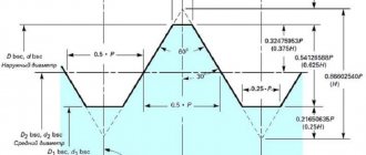
Pipe thread profile
GOST 6357-81 regulates the main parameters of the profile. The required dimensions in millimeters are given in the table.
Table 1
| Step | Height of the original triangle | Number of steps per length 2.54 cm | Profile height (working), *10-1 | Radius of curvature of the root and top of the thread, *10-1 |
| 0,907 | 0,871165 | 28 | 5,80777 | 1,24557 |
| 1,337 | 1,284176 | 19 | 8,56117 | 1,83609 |
| 1,814 | 1,742331 | 14 | 11,61553 | 2,49115 |
| 2,309 | 2,217774 | 11 | 14,78515 | 3,17093 |
The pitch value of a cylindrical pipe thread (GOST 6357) is determined from the ratio of 25.4 mm/number of steps. The result is rounded to thousandths and taken as the initial one for calculating the main profile parameters.
Note! It is allowed to make the tops of external and internal threads with a flat cut, if the possibility of connection with a conical external thread according to document 6211 is excluded.
Pitch is one of the defining parameters of pipe threads
The main dimensions in millimeters, which are determined by GOST for pipe threads, are presented in Table 2. Symbols accordingly: a – 1/16, c – 1/4, e – 1/2, f – 3/4, g – 5/8 , h – 7/8, j – 1 1/4, d – 3/8, k – 1 1/8, m – 1 3/8, n – 1 3/4, l – 1 1/2, o – 2 1/2, q – 2 3/4, r – 3 1/4, s – 3 1/2, p – 2 1/4, t – 3 3/4, u – 4 1/2, v – 5 ½, b – 1/8.
Table of rod diameters for external threads
When working with external threads, the situation is very similar - part of the metal is extruded rather than cut off. Therefore, the diameter of the rod or pipe on which the thread is applied should be slightly smaller. How accurate - see the table below.
| Thread diameter, mm | 5,0 | 6 | 8 | 10 | 12 | 16 | 20 | 24 |
| Rod diameter, mm | 4,92 | 5,92 | 7,9 | 9,9 | 11,88 | 15,88 | 19,86 | 23,86 |
Despite the fact that cutting internal threads is not a complex technological operation, there are some features of preparation for this procedure. Thus, it is necessary to accurately determine the dimensions of the preparation hole for threading, and also select the right tool, for which special tables of drill diameters for threads are used. For each type of thread, it is necessary to use the appropriate tool and calculate the diameter of the preparation hole.
Table
The following is a table of threads containing information about the main parameters of pipes. We recommend that you refer to this table when, for example, renovating a bathroom:
| Thread, inches | Dimensions, mm | Number of threads | ||||||
| diameter | thread pitch | profile height | radius | per inch | by 127 mm | |||
| outer | interior | average | ||||||
| 1/8 | 9,729 | 8,567 | 9,148 | 0,907 | 0,581 | 0,125 | 28 | 140 |
| 1/4 | 13,158 | 11,446 | 12,302 | 1,337 | 0,856 | 0,184 | 19 | 95 |
| 3/8 | 16,663 | 14,951 | 15,807 | 1,337 | 0,856 | 0,184 | 19 | 95 |
| 1/2 | 20,956 | 18,632 | 19,794 | 1,814 | 1,162 | 0,249 | 14 | 70 |
| 5/8 | 22,912 | 20,588 | 21,750 | 1,814 | 1,162 | 0,249 | 14 | 70 |
| 3/4 | 26,442 | 24,119 | 25,281 | 1,814 | 1,162 | 0,249 | 14 | 70 |
| 7/8 | 30,202 | 27,878 | 29,040 | 1,814 | 1,162 | 0,249 | 14 | 70 |
| 1 | 33,250 | 30,293 | 31,771 | 2,309 | 1,479 | 0,317 | 11 | 55 |
| 1 1/8 | 37,898 | 34,941 | 36,420 | 2,309 | 1,479 | 0,317 | 11 | 55 |
| 1 1/4 | 41,912 | 38,954 | 40,433 | 2,309 | 1,479 | 0,317 | 11 | 55 |
| 1 3/8 | 44,325 | 41,367 | 42,846 | 2,309 | 1,479 | 0,317 | 11 | 55 |
| 1 1/2 | 47,805 | 44,817 | 46,326 | 2,309 | 1,479 | 0,317 | 11 | 55 |
| 1 3/4 | 53,748 | 50,791 | 52,270 | 2,309 | 1,479 | 0,317 | 11 | 55 |
| 2 | 59,616 | 56,659 | 58,137 | 2,309 | 1,479 | 0,317 | 11 | 55 |
| 2 1/4 | 65,712 | 62,755 | 64,234 | 2,309 | 1,479 | 0,317 | 11 | 55 |
| 2 1/2 | 75,187 | 72,230 | 73,708 | 2,309 | 1,479 | 0,317 | 11 | 55 |
| 2 3/4 | 81,537 | 78,580 | 80,058 | 2,309 | 1,479 | 0,317 | 11 | 55 |
| 3 | 87,887 | 84,930 | 86,409 | 2,309 | 1,479 | 0,317 | 11 | 55 |
| 3 1/4 | 93,984 | 91,026 | 92,505 | 2,309 | 1,479 | 0,317 | 11 | 55 |
| 3 1/2 | 100,334 | 97,376 | 98,855 | 2,309 | 1,479 | 0,317 | 11 | 55 |
| 3 3/4 | 106,684 | 103,727 | 105,205 | 2,309 | 1,479 | 0,317 | 11 | 55 |
| 4 | 113,034 | 110,077 | 111,556 | 2,309 | 1,479 | 0,317 | 11 | 55 |
| 4 1/2 | 125,735 | 122,777 | 124,256 | 2,309 | 1,479 | 0,317 | 11 | 55 |
| 5 | 138,435 | 135,478 | 136,957 | 2,309 | 1,479 | 0,317 | 11 | 55 |
| 5 1/2 | 151,136 | 148,178 | 149,657 | 2,309 | 1,479 | 0,317 | 11 | 55 |
| 6 | 163,836 | 160,879 | 162,357 | 2,309 | 1,479 | 0,317 | 11 | 55 |
Thus, we considered only the main types that are most often found in everyday life. For more accurate information, there are regulatory documents, GOSTs, which contain detailed information about the types and characteristics.
As a rule, it is very difficult to visually distinguish their type. For this purpose, there are thread tables in which, having measured the main parameters in advance, you can determine its type.
Types and parameters of thread
The parameters by which threads are divided into different types are:
- units of diameter (metric, inch, etc.);
- number of thread starts (one-, two- or three-thread);
- the shape in which the profile elements are made (triangular, rectangular, round, trapezoidal);
- direction of rise of turns (right or left);
- location on the product (external or internal);
- surface shape (cylindrical or conical);
- purpose (fastening, fastening and sealing, chassis).
Depending on the above parameters, the following types of thread are distinguished:
- cylindrical, which is designated by the letters MJ;
- metric and conical, designated M and MK respectively;
- pipe, designated by the letters G and R;
- with a round profile, named after Edison and marked with the letter E;
- trapezoidal, designated Tr;
- round, used for installation of sanitary fittings, – Kr;
- thrust and thrust reinforced, marked as S and S45, respectively;
- inch thread, which can also be cylindrical and conical - BSW, UTS, NPT;
- used to connect pipes installed in oil wells.
Characteristics of inch thread
The regulatory document that describes inch cylindrical pipe threads - GOST 6357-81 - insists that the main characteristics of such a thread are its diameter and its pitch. Moreover, the thread diameter is understood as either the distance between the opposite upper points lying on the tops of the threaded ridges (outer diameter), or the distance between the opposite lower points lying on the depressions of the threaded groove (inner diameter). The difference between these diameters determines the height of the thread profile.
The next characteristic, the pipe thread pitch, is determined as the distance between two adjacent valleys or two adjacent crests. Moreover, the pitch of the thread is always the same, no matter how you measure it. After all, the distance between the turns must be stable. Otherwise, we will not be able to select a pair (nut or bolt) for the threaded connection.
Application of the tap
Before you start threading, you need to determine the diameter of the preparation hole and drill it. To facilitate this task, a corresponding GOST was developed, which contains tables that allow you to accurately determine the diameter of the threaded hole. This information makes it easy to select the drill size.
To cut metric threads on the inner walls of a hole made with a drill, a tap is used - a screw-shaped tool with cutting grooves, made in the form of a rod, which can have a cylindrical or conical shape. On its side surface there are special grooves located along its axis and dividing the working part into separate segments, which are called combs. The sharp edges of the combs are precisely the working surfaces of the tap.
In order for the turns of the internal thread to be clean and neat, and for its geometric parameters to correspond to the required values, it must be cut gradually, by gradually removing thin layers of metal from the surface being treated. That is why for this purpose they use either taps, the working part of which is divided along the length into sections with different geometric parameters, or sets of such tools. Single taps, the working part of which has the same geometric parameters along its entire length, are needed in cases where it is necessary to restore the parameters of an existing thread.
The minimum set with which you can sufficiently perform machining of threaded holes is a set consisting of two taps - rough and finishing. The first one cuts a thin layer of metal from the walls of the hole for cutting metric threads and forms a shallow groove on them, the second one not only deepens the formed groove, but also cleans it.
Combination two-pass taps or sets consisting of two tools are used for tapping small diameter holes (up to 3 mm). To machine holes for larger metric threads, you must use a combination three-pass tool or a set of three taps.
To manipulate the tap, a special device is used - a wrench. The main parameter of such devices, which can have different designs, is the size of the mounting hole, which must exactly match the size of the tool shank.
When using a set of three taps that differ both in their design and geometric parameters, the sequence of their use must be strictly observed. They can be distinguished from each other both by special marks applied to the shanks and by design features.
- The tap, with which the hole for cutting metric threads is processed first, has the smallest diameter among all the tools in the set and cutting teeth, the upper part of which is heavily cut off.
- The second tap has a shorter fence and longer combs. Its working diameter is intermediate between the diameters of the other tools in the set.
- The third tap, with which the hole for cutting metric threads is processed last, is characterized by full ridges of cutting teeth and a diameter that must exactly match the size of the thread being formed.
Taps are used primarily for cutting metric threads. Much less often than metric ones, taps designed for processing the internal walls of pipes are used. In accordance with their purpose, they are called pipe, and they can be distinguished by the letter G present in their markings.
Pipe thread - types, sizes, GOSTs
One of the ways to connect pipes is a thread - a spiral with a constant pitch.
Pipe threads differ in the following parameters:
- Diameter measuring system: metric and inch thread
- Thread direction: right, left
- Thread location: external, internal
- Number of passes: single-pass, multi-pass
- Purpose: fastening, fastening and sealing, running, special, etc.
The main characteristics of pipe threads are:
- External diameter
- Inner diameter
- Pitch - the distance between adjacent turns
- Stroke is the distance that the fastener moves in the longitudinal direction in one full revolution. With single-pass knurling, the stroke is equal to the step, with multi-pass knurling - the step multiplied by the number of passes.
Metric thread
Metric thread is characterized by measuring the main parameters in millimeters; according to GOST, it corresponds to the marking “M”. Widely used in diameters from 1 to 600 mm and pitches of 0.25 to 6 mm. The metric thread profile is an equilateral triangle with an apex angle of 60° and a theoretical height of H-0.866025404. The main dimensions of metric threads are currently determined according to the current GOST 24705-2004, adopted by the Interstate Council for Standardization, Metrology and Certification, as well as national standardization bodies of the Russian Federation, Azerbaijan, Armenia, Belarus, Georgia, Kazakhstan, Kyrgyzstan, Moldova, Tajikistan, Turkmenistan, Uzbekistan, Ukraine.
Inch thread
With inch threads, all parameters are expressed in inches, according to GOST it is designated “Tr”. Inch threads are based on the British standard Whitworth (BSW), patented by the English engineer Whitworth back in 1841, and correspond to the BSPT (British standard pipe thread) standard. One inch is equal to 2.54 cm, and the graphic symbol for an inch is a double stroke to the right and above the number (1″ = 1 inch). With inch pipe threads, the size refers to the inner diameter of the pipe, not the outer diameter. There are four pitch options: 28, 19, 14 and 11 threads per inch. Inch profiles are distinguished by sharper crests and valleys with angles of 55° and a theoretical height of H = 0.960491, while the tops of the teeth are rounded. It is impossible to combine metric and inch threads in one connection; a special adapter is required for this. The size of the pipe inch thread is determined according to the current GOST 6357-81 “Basic standards of interchangeability”.
Pipe Thread Size Chart
| Designation | Diameter in inches | External diameter in mm | Inner diameter in mm | Thread diameter in mm | Steps per inch |
| G 1/8″ | 1/8 | 9,73 | 8,85 | 8,80 | 28 |
| G 1/4″ | 1/4 | 13,16 | 11,89 | 11,80 | 19 |
| G 3/8″ | 16,66 | 15,39 | 15,25 | 19 | |
| G 1/2″ | 1/2 | 20,95 | 19,17 | 19,00 | 14 |
| G 5/8″ | 5/8 | 22,91 | 21,13 | 21,00 | 14 |
| G 3/4″ | 3/4 | 26,44 | 24,66 | 24,50 | 14 |
| G 7/8″ | 7/8 | 30,20 | 28,42 | 28,25 | 14 |
| G 1″ | 1 | 33,25 | 30,93 | 30,75 | 11 |
| G 1 1/8″ | 1 1/8 | 37,90 | 35,58 | 35,30 | 11 |
| G 1 1/4″ | 1 1/4 | 41,91 | 35,59 | 39,25 | 11 |
| G 1 3/8″ | 1 3/8 | 44,32 | 42,00 | 41,70 | 11 |
| G 1 1/2″ | 1 1/2 | 47,80 | 45,48 | 45,25 | 11 |
| G 2″ | 2 | 59,61 | 57,29 | 57,00 | 11 |
| G 2 1/4″ | 2 1/4 | 65,71 | 63,39 | 63,10 | 11 |
| G 2 1/2″ | 2 1/2 | 75,18 | 72,86 | 72,60 | 11 |
| G 2 3/4″ | 2 3/4 | 81,53 | 79,21 | 78,90 | 11 |
| G 3″ | 3 | 87,88 | 85,56 | 85,30 | 11 |
| G 3 1/4″ | 3 1/4 | 93,98 | 91,66 | 91,50 | 11 |
| G 3 1/2″ | 3 1/2 | 100,33 | 98,01 | 97,70 | 11 |
| G 3 3/4″ | 3 3/4 | 106,68 | 104,3 | 104,00 | 11 |
| G 4″ | 4 | 113,03 | 110,71 | 110,40 | 11 |
Conventional inch thread
In the USA and Canada, the so-called inch thread, or UTS (Unified Thread Standard), is common. It is characterized by an apex angle of 60° and a theoretical profile height of H=0.866025P. Depending on the step, UTS, in turn, is divided into the following standards: • UNC (Unified Coarse); • UNF (Unified Fine); • UNEF (Unified Extra Fine); • 8UN; • UNS (Unified Special).
Edison profile (round thread)
To connect pipes, a round thread, or the so-called Edison profile, is sometimes used. The profile of this type of pipe thread is characterized by alternating convex and concave arcs with the same radius. The round thread type is used in connections that are subject to frequent loosening and screwing, as it provides high wear resistance.
Straight thread
Straight pipe threads are used to connect pipes, pipeline fittings and fittings with a diameter of 1/16 to 6 inches with a thread count of 28 to 11 per inch. The regulatory document for cylindrical pipe threads is GOST 6367-81, according to which the symbols for marking cylindrical pipe threads must include the letter G, the designation of the thread size and the accuracy class of the average diameter. For left-hand threads, the symbol LH is adopted. A threaded connection is designated by a fraction, the numerator of which indicates the accuracy class of the internal thread, and the denominator - the external thread. Internal cylindrical pipe threads in accordance with GOST 6357-81 are compatible with external conical threads in accordance with GOST 6211-81. Complies with BSPP standard.
Tapered thread (BSPT - trapezoidal)
Tapered pipe threads are used to ensure tightness and locking without the use of a key, therefore, with this type of connection of parts, the necessary effect is achieved by deforming the thread.
Today, the most common standard of foreign technology is metric - marked ISO. Other standards are also quite widespread in the world, which is due to historical differences in the systems of measures in different countries. Additionally, whether an inch or metric thread is used depends on the application. Thus, in residential construction, as a rule, pipes are used that meet international standards for cylindrical inch threads of ¼, ½ and 1 inch. Metric threads are used in industry. Tapered pipe threads are characterized by exceptional reliability of pipe connections, therefore they are used in pipelines operating under high pressure: in gas and oil production, on drilling rigs. The American standard for inch pipe thread UNC 1/4 (1/4″x1.25 mm) is accepted throughout the world for use in mounting photographic and video equipment.
Pipe thread sizes
- Pipe thread sizes are determined using a special table after measuring the main parameters:
- pitch (P) - the distance between the same side sides of the profile, measured in fractions of a meter, in fractions of an inch or the number of threads per inch (the denominator of a simple fraction, where the numerator is an inch, expressed as a natural number)
- outer diameter (D, d) – the diameter of the cylinder described around the tops of the external (d) or the bottoms of the internal thread (D).
- average diameter (D2, d2) – the diameter of the cylinder, the generatrix of which intersects the thread profile in such a way that its segments formed at the intersection with the groove are equal to half the nominal thread pitch.
- internal diameter (D1, d1) - the diameter of the cylinder inscribed in the recesses of the external (d1) or the top of the internal thread (D1)
- stroke (Ph) – the magnitude of the relative movement of the initial midpoint along the helical line of the thread at an angle of 360°.
How to cut threads - thread-cutting equipment and tools
The choice of thread-cutting equipment depends on the type and scale of production, material and size of pipes, requirements for thread accuracy and other factors.
Threads can be obtained by rolling or cutting.
Rolling threads are produced using special thread-cutting rollers. To do this, the workpiece is placed between rollers with the required thread contour and thread turns are rolled on automatic and semi-automatic thread rolling machines, and sometimes on lathes and turret machines. Due to the smooth distribution of stress waves between turns due to metal deformation, such threads are distinguished by high mechanical characteristics and high performance. However, the accuracy of the rollers used must be at a very high level, and the manufacturing material must have improved mechanical properties - most often high-alloy stamped steel is used.
Cut threads are easier to manufacture, but in terms of mechanical properties and endurance limit they are inferior to rolled threads. This is due to the presence of sharper profile edges and a higher stress factor.
According to the method of thread cutting, it is divided into manual and using a special machine.
When manually cutting, special devices are used: a tap (for internal pipe threads) and dies (for external pipe threads), or a special thread-cutting hand tool - a die, which carries out cutting using movable adjustable comb cutters. Manual cutting is recommended for pipe diameters up to 1 inch, since larger diameters require significantly more physical effort.
For large loads and volumes of work, today there is a huge selection of reliable threading tools: from portable electric threading tools to special machines that can cope with cutting threads of any type on pipes of various diameters from any materials.
Our company ITC (ITC) offers a wide range of Ridgid and Rex thread-cutting tools. We are the official dealers of these brands in Russia, so we can offer not only the best prices, but also warranty and post-warranty service.
The range of presented threading tools can be viewed in our catalog: Catalog >>> Threading tools >>> Threading machines Threading heads Manual and electric clamps Combs and rollers
Are you unsure about choosing the right tapping tool? Don't know how to choose the right slicing equipment? Contact our managers for professional advice! Call +7 495 232-90-35, write an email or leave a request on the website.
Request a call