How to properly charge lithium batteries
There are several charging schemes for lithium batteries. Two-stage charging developed by SONY is most often used. Devices using pulse charging and step-by-step charging, as for acid batteries, are not used.
Charging any type of lithium ion or lithium polymer battery requires strict adherence to voltage. One cell of a charged lithium battery should have no more than 4.2 V. The nominal voltage for them is considered to be 3.7 V.
Can lithium batteries be charged quickly, but not fully? Yes. They can always be recharged. Operating the battery at 40-80% capacity extends the battery's shelf life.
Two-stage lithium battery charging circuit
The principle of the CC/CV circuit is constant charging current/constant voltage. How to charge a lithium battery using this scheme?
The diagram before stage 1 of charging shows the pre-stage for restoring a deeply dead lithium battery, with a voltage at the terminals of at least 2.0 V. The first stage should restore 70-80% of the capacity. The charging current is selected at 0.2-0.5 C. You can quickly charge with a current of 0.5-1.0 C. (C is the capacity of lithium batteries, digital value). What should the charging voltage be at the first stage? Stable, 5 V. When the voltage at the battery terminals is 4.2, this is a signal to move to the second stage.
Now the charger maintains a stable voltage at the terminals, and the charging current decreases as the capacity rises. When its value decreases to 0.05-0.01 C, charging will end and the device will turn off, preventing recharging. The total capacity recovery time for a lithium battery does not exceed 3 hours.
If the lithium-ion battery is discharged below 3.0V, a “jump” will be required. This consists of charging with a low current until there is 3.1 V at the terminals. Then the usual circuit is used.
How to control charging parameters
Since lithium batteries operate in a narrow range of voltage changes at the terminals, they cannot be recharged above 4.2 V and discharged below 3 V. The charge controller is installed in the charger. But each battery or battery has its own breakers, PCB board or PCM protection modules. The batteries are equipped with protection against one or another factor. If the parameter is violated, it must turn off the jar and break the circuit.
A controller is a device that must implement control functions - switch CC/CV modes, control the amount of energy in the banks, turn off charging. At the same time, the assembly works and heats up.
Homemade charging circuits used for lithium batteries
- LM317 – circuit of a simple charger with a charge indicator. It is not powered from the USB port.
- MAX1555, MAX1551 - specially for Li batteries, installed in the power adapter from the phone to USB. There is a pre-charge function.
- The LP2951 stabilizer limits the current and generates a stable voltage of 4.08-4.26V.
- MCP73831 is one of the simplest circuits, suitable for charging ionic and polymer devices.
If the battery consists of several cells, they are not always discharged evenly. When charging, a balancer is needed to distribute the charge and ensure uniform charging of all the cells in the battery. The balancer can be separate or built into the battery connection circuit. The battery protection device is called BMS. Knowing how to charge devices and understanding the circuits, you can assemble a protective device circuit for a lithium battery with your own hands.
Charging station repair
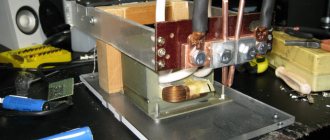
They fix simple problems with their own hands. An example of repair is shown on the 12V DA-10/12ER station for lithium-ion batteries with a voltage of 12 V, current 1.8 A. The device consists of a step-down transformer, a four-diode bridge, smoothing out the ripple of the capacitor. LEDs indicate power connection, start and end of charging.
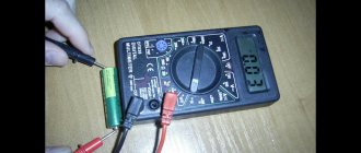
If the power indicator does not light up, check the primary winding of the transformer. To do this, measure the resistance with a tester by touching the probes of the plug with the probes. If there is a break, open the case. The mains fuse may have blown and needs to be replaced.
Some charger models have a thermal fuse. It is located on top of the primary winding of the transformer under insulation, breaks the circuit at a temperature of +120...+130°C. Restoration is impossible; they proceed in a different way: they connect the ends of the windings by soldering. After this operation, the transformer is not protected from short circuits, so it is better to install a mains fuse.
When the primary winding is intact, the secondary and diodes ring. One end of the semiconductors is unsoldered, an ohmmeter is connected, changing the position of the probes. A working diode shows an open circuit with one connection, and a short circuit with the other. A burnt-out primary winding cannot be repaired - the transformer is replaced.
We advise you to study Hidden Wiring Finder
If faulty diodes are found, install new ones. At the same time, the capacitor is also changed: if the electrolyte dries out in it, the diodes overload and burn out.
The board is examined under a magnifying glass. Eliminate detected cracks and broken contacts. If all the measures taken do not help, contact the workshop.
Features of lithium batteries
Li-ion batteries are very unpretentious to use. If handled with care, they will last about 3-4 years. However, it is worth focusing on the fact that even if batteries are not used, they slowly die. Therefore, stocking up on batteries for the device for future use is not entirely reasonable. 2 years is the normal time from the date of production. If more has passed, then these may be already failed batteries.
Interesting. The most common 18650 can size has an average capacity of 3500 mAh. The normal price for such a battery is 3-4 dollars. Therefore, manufacturers who promise a 10,000 mAh Power bank for $3 are, to put it mildly, deceiving. It would be good if there was at least 3000 mAh.
DIY charger for lithium 18650 batteries
Batteries play an important role in any mechanism that does not operate from the mains. Rechargeable batteries are quite expensive due to the fact that you need to purchase a charger along with them. Batteries use different combinations of conductor materials and electrolytes - lead-acid, nickel-cadmium (NiCd), nickel-metal hydride (NiMH), lithium-ion (Li-ion), lithium-ion polymer (Li-Po).
I use lithium-ion batteries in my projects, so I decided to make my own charger for 18650 lithium batteries rather than buy an expensive one, so let's get started.
Lithium batteries
Next, I bought 10 lithium batteries and assembled 2 batteries from them in parallel, and then connected the 5 resulting blocks in series. The batteries were connected to each other by soldering using pre-tinned copper plates. For soldering you need one basic rule - do not overheat the battery! Therefore, you need to solder with a powerful soldering iron and as quickly as possible in 1-2 seconds. If it doesn’t work right away, it’s better to wait and not boil the battery.
The consequences of overheating can lead to fire and burns. Be careful!
Those who have spot welding will have no problems with the connection. As a result, a battery with a voltage of 21 V and a capacity of 5.2 Ah was assembled. The connection of the battery to the control board is shown in the figure.
Next, everything is packed into a case and tested under load.
I integrated an LM2596 module into the standard charger. The power supply should be a couple of volts higher than the voltage of the charged battery. I set the idle voltage to 21 V. Then I connected the battery and set the charging current to 0.8 A. Why is this? Because there was a 24 V power supply with a max. current 0.8 A. I did not purchase it specifically. Let it take longer to charge. This is not a production, but a home version of the tool.
During the charging process, a small minus was revealed. When the battery voltage reaches full charge, the charger must move from the CC phase to the CV phase. That is, first the battery is charged with a set current (0.8 A in my case), and when 21 V is reached, the voltage is maintained at this level, and the current gradually drops to 0.1 * Iset (in my case 0.08 A, set by the middle potentiometer ). This stops the charging process. On this module, this is indicated by the middle LED, but it only signals that the battery is ready for use, but in fact charging continues, which in principle is not critical. The battery will still not be recharged. The downside is that due to the fact that the control board has its own overcharge protection, it turns off the charger before reaching the CV phase.
To get around this, it was necessary to reduce the voltage of the charger module to approximately 20.7-20.8 V. The CV phase begins earlier, but in any case, the battery is charged more fully than without it at all. If you are not aware of this small drawback, then you will not notice the difference during operation.
How to make a charger for a lithium battery with your own hands
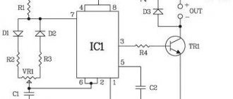
Let's look at one of the simplest charger circuits for lithium-ion batteries. A homemade charging circuit is implemented on a microcircuit that acts as a zener diode and charge controller, and a transistor. The base of the transistor is connected to the control electrode of the microcircuit. Lithium batteries do not like overvoltage, so the output voltage must be set to the recommended voltage of 4.2 V. This can be achieved by adjusting the microcircuit with resistances R3 R4, which have values of 3 kOhm and 2.2 kOhm, respectively. They are connected to the first leg of the microcircuit. The adjustment is set once, and the voltage remains constant.
To be able to adjust the output voltage in place of the resistor R, install a potentiometer. The adjustment must be made without a load, that is, without the battery itself. With its help, you can precisely adjust the output voltage to 4.2 V. Then, instead of the potentiometer, you can install a resistor of the obtained value.
Resistor R4 is used to turn on the base of the transistor. The nominal value of this resistance is 0.22 kOhm. As the battery charges, its voltage will increase. This will cause the control electrode on the transistor to increase the emitter-collector resistance. This, in turn, will reduce the current going to the battery.
You also need to adjust the charging current. To do this, use resistance R1. Without this resistor, the LED will not light up; it is responsible for indicating the charging process. Depending on the required current, a resistor with a nominal value of 3 to 8 ohms is selected.
How to charge a screwdriver battery without a charger
Power supply.
The design of an electric tool uses 3 types of power sources:
- Nickel-cadmium elements, characterized by their ability to withstand high loads and operate at negative air temperatures.
- Batteries are characterized by a pronounced memory effect and accelerated self-discharge. Before connecting the battery to the charging station, the battery must be completely discharged.
- A short-term connection of the battery bank to a non-original charging unit is allowed.
- Nickel-metal hydride cells have a reduced memory effect and increased capacity. It is not recommended to connect batteries to non-original chargers.
- Lithium-ion power supplies that do not allow deep discharge and overheating. For charging, special units with microprocessor control are used that monitor the state of the elements. It is prohibited to use charging units from car batteries or other power sources.
Before connecting the external unit, you need to find out the type, capacity and charging current of the power source. The information is indicated on the manufacturer's label located on the body of the battery can. If the sticker is lost, you will need to open the casing and find out the operating parameters from the markings on the elements.
When switching the external unit, it is important to take into account the voltage matching. For example, short-term switching of a 12 V unit to a 9 V battery is allowed, but the battery life is reduced.
Via USB
To replenish the capacity, it is possible to connect an external charging unit via a self-installed USB port. It is recommended to use adapters rated for a current of 5-7 A. It is not recommended to use computers or laptops to supply current, since the increased current in the circuit overheats the controller and disables the unit.
Algorithm for equipping a screwdriver battery with a USB connector:
- Remove the battery bank, and then separate the sections of the case (the elements are held on by screws and additional plastic clips).
- Cut a hole in the housing section to install a USB connector. The port installation location should not interfere with the placement of the power source in the tool handle or in a standard charging station. The channel configuration depends on the appearance of the prepared plug. The block is installed in the resulting socket and fixed using special hot-melt adhesive.
- Place a 10 A fuse in the circuit connecting the standard charging controller and the USB connector. Hot-melt adhesive is used to secure the protective element and electrical wiring. The cables are connected by soldering with lead-tin solder, the fixation points are protected with insulating materials.
- Connect the body sections using standard screws. If a permanent structure was cut, the joint line is covered with a strip of fabric or masking tape coated with liquid epoxy resin. After the material hardens, the surface is sanded and painted to match the color of the battery can body.
- Carry out test charging of the DC source. Since the voltage in the charging circuit is 5 V, replenishing the capacity takes up to 6-8 hours for batteries with a capacity of 1-2 Ah.
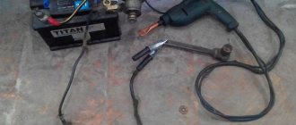
Using a car charger
Charger for car.
Using a charger designed to service a 12-volt vehicle battery may permanently damage the power source for the power tool.
Before connecting devices, it is necessary to bring the charging operating parameters to the necessary requirements.
If the equipment is equipped with stepless voltage and current regulators, then it is necessary to set parameters identical to the standard unit. To reduce the current load, a ballast resistor is used (for example, a car parking light lamp).
If information about the operating parameters of standard charging is unknown, then for a nickel-cadmium battery with a capacity of 1.3 A*h the charging current is set within 50-100% of the nominal capacity. The voltage is set to the minimum level. Then the polarity of the battery bank is determined (according to the factory markings), the location of the minus and plus is, if necessary, clarified with a test device.
The nickel-cadmium can is charged until the peak voltage is reached, which is not detected by the car unit. In domestic conditions, the moment of charging termination is determined by the temperature of the elements’ housing, which is no more than 40°C.
To take measurements, you need to drill through the plastic casing of the can and install a sensor inside (for example, from a household test device). Depending on the current parameters, charging lasts from 30 minutes to 2 hours; when the threshold temperature is reached, the external unit turns off.
Universal memory
Universal battery charging equipment supports stepwise or continuous adjustment of voltage and current in the output circuit. The unit is equipped with instruments and indicators that allow you to monitor the charging progress.
If the device design includes a battery type switch, then you must select the appropriate value. Universal charging equipment is recommended for servicing worn-out elements.
Using an external power source
The technique involves connecting the tool to a car battery or charging station using cables. The voltage of the external power source must match the parameters of the electric motor. When the tool is operating, the load on the motor changes, which leads to a change in the current in the circuit. The external power supply must ensure the operation of the engine and not overheat during long-term operation.
A fuse is provided in the power circuit; the rating depends on the motor power and operating voltage. For example, when installing a motor with a power of 200 W and a voltage in the power circuit of 18 V, you will need to install a fuse link with a rating of at least 200/18 = 11 A. Using a fuse with oversized parameters leads to overheating and destruction of the motor windings. When making connecting wiring, the current strength in the power circuit is taken into account.
The cables are equipped with a connection block made independently or removed from a standard faulty battery bank. The plug is secured with adhesive tape. It is not recommended to glue the block, as it will be difficult to separate the parts.
How to charge a battery, rules
Lithium-ion batteries are similar to people in that they do not behave the same and work best at temperatures that are neither too hot nor too cold.
These batteries perform better at high temperatures than at low temperatures because the heat reduces internal resistance and speeds up the chemical reaction inside the battery. A side effect of this process is that it puts a strain on the battery, which can lead to shortened life in hot conditions for extended periods.
On the other hand, low temperatures increase internal resistance, which increases the load on the battery and reduces its capacity. Batteries that provide 100% capacity at 27°C are typically reduced by 50% at -18°C and so on.
How to charge Li ion batteries correctly?
Do not discharge completely
Failure to follow these tips and instructions may damage the battery to the point that it becomes unusable. You may also endanger your safety and the safety of others if the battery is not used properly. When combined with a mismatched charger, overheating or overcharging may occur and there is a risk of fire.
Complete discharge is carried out no more than once every 3 months
How to properly charge lithium ion batteries?
Charging lithium ion batteries is very different from charging nickel-cadmium or nickel-metal hydride batteries.
The differences are that lithium-ion batteries have a higher voltage per cell. They also require much tighter voltage tolerances when detecting a full charge, and once fully charged they do not allow or require recharging
It is especially important to be able to accurately determine the state of full charge since lithium-ion batteries cannot be overcharged
Low charge storage
Most consumer-oriented lithium-ion batteries charge to 4.2V per cell, and this allows for a deviation of about ±50mV per cell. Charging beyond this stresses the cell and leads to oxidation, which reduces life and performance. This may also cause security problems.
Charge only with original charger
Charging lithium-ion batteries can be divided into two main stages:
- Constant current charging: In the first stage of charging a lithium-ion battery or cell, the charging current is controlled. Typically, this is between 0.5 and 1.0 C. (Note: For a 2000 mAh battery, the charging rate will be 2000 mA for the C charging rate). For LCO consumer cells and batteries, a charging rate of no more than 0.8 °C is recommended. At this point, the voltage across the lithium ion cell is increased for constant current charging. Charging time can be around an hour for this stage.
- Charge Saturation: After some time, the voltage peaks at 4.2V for the LCO cell. At this point, the cell or battery should enter the second stage of charging, known as saturation charge. A constant voltage of 4.2V is maintained and the current will drop continuously. The end of the charging cycle is reached when the current drops to approximately 10% of the rated current. Charging time can be around two hours for this stage depending on cell type and manufacturer, etc.
We advise you to study Impedance
Charge efficiency, that is, the amount of charge held by a battery or cell relative to the amount of charge entering the cell, is high. Charging efficiency is between 95 and 99%. This reflects relatively low levels of cell temperature rise.
Do not overheat the battery when charging
There are times when you cannot use the battery for an extended period of time. Here are tips for maintaining maximum battery capacity for long-term storage.
Converting a screwdriver battery to lithium cells
I’ll speak out, hehe, since there’s such a booze... This is my second Shurik, with a power of 18 V. I’m not a techie, I don’t have dachas, garages, businesses, hacks. It’s just that in life I don’t like to beg and borrow, including matches, salt, a cigarette, especially a mallet, a vice, a vise, a stapler, a mite, a hammer, a plane, a sherhebel, a hacksaw, a chisel, a glass cutter, a square, level, paint brushes, spatula, jigsaw, drill, angle grinder, wall cutter, of course, shura, etc., etc. I used separate hand and power tools once or twice, bought them for a specific job - for example, I made laminate slopes myself for the front door. In Shurik there are nickel-cadmium batteries, the third year is ending, I regularly pump them (discharge-charge-discharge-charge). Sometimes, to test the power, I screw a couple of 100 mm pieces into an oak block - with a creak, dry. There is plenty of power. Very satisfied. The new Shurik was involved in a major job four times - he remodeled the balcony (dismantled the plastic and covered it with clapboard), renovated the basement and under... I think the batteries will last another three or four years. I keep an eye on them, the main thing is that I know that I received them OBVIOUSLY new when I purchased them, or rather (the whole story), when they were handed to me by a sales representative of the factory. I am convinced that 50-70% of the problems of users of nickel-cadmium batteries are that they are being peddled with stale goods, ones that, in fact, should have been written off a year or two ago or discounted by 50-80%. Due to half-dead, or even dead, battery cans (one, for sure). They also sold me stale shurik, and once you determine the condition of the cans, no one will let you open the battery. It’s good that Shurik allowed us to finish the renovations in the kitchen, assemble new furniture, and even install slopes. And both batteries died immediately. I split open the leaking cans, two or three at a time. So what do you want me to do? The warranty year passed two weeks ago. Okay, I think I’ve redone everything that’s important, but in some small things I could use screwdrivers. A year later, there was still work for Shurik. I began to think about buying an electric Shurik... And suddenly anger flared up at the online seller of the dead Shurik (I couldn’t find any traces - did they change the location, the name?). I started looking for the manufacturer's address. And somehow I found it and wrote a complaint... In the spirit that your Shurik is excellent, no worse than Makit and Hilti, but you install some half-dead batteries... And the manufacturer, exactly in the year of my application, launched a new model of Shurik - the color became brighter, more beautiful , and everything became more elegant. Well, a representative of the plant comes to me and takes away my old Shurik and gives me a fresh one. The suitcase was changed to a suitcase. I don't need anything better. If the nickel-cadmium batteries become obsolete, I’ll insert lithium ones, either myself or through a workshop (I’m already old) and buy a new lithium charger. I'll give a shurik to my son-in-law. Let him join in... The new batteries are already three years old, and the powerful ones are like tigers. I take care of them. I’ll see how long normal batteries can survive under the worst semi-unemployment situation for them. Most Shurik consumers take them for some one-time and then periodic service. It's a terrible life for nickel-cadmium. They need complete discharge and full charging, at least 1-2 times a month. It is advisable to store in a dry and cool (cold) place. Shurik is separate from the battery.
Types of chargers
The popularity of a screwdriver is due to the fact that it simplifies the process of tightening or unscrewing various fasteners. Characterized by its mobility and small size, it is indispensable for assembling furniture structures, dismantling equipment, roofing and other construction work. The tool owes its mobility to the batteries included in its design.
The screwdriver battery is charged in two ways: with a built-in or external charger. The built-in charger allows you to charge the battery without removing it from the screwdriver. The capacity restoration circuit is located directly with the battery. While remote means their removal and installation in a separate device for charging. Chargers are distinguished according to the type of recoverable batteries. The batteries used are:
- nickel-cadmium (NiCd);
- nickel metal hydride (NiMH);
- lithium-ion (LiIon).
The final cost of a screwdriver depends not least on the type of batteries used and the capabilities of the charger. Chargers are available in 12 volts, 14.4 volts and 18 volts. In addition, memories are divided according to capabilities and may have:
- indication;
- fast charging;
- different type of protection.
The most used chargers use a slow charge due to low current. They do not contain an operation indication in their design and do not turn off automatically. This is more true for built-in capacity restoration devices. Chargers built on pulse circuits provide the possibility of accelerated charging. They automatically turn off when the required voltage is reached or in the event of an emergency.
Types of batteries used
Nickel-cadmium batteries do not experience problems when charging in accelerated mode.
Such batteries have a high load capacity, low price and can easily withstand work at sub-zero temperatures. Disadvantages include: memory effect, toxicity, high self-discharge rate. Therefore, before charging this type of battery, it must be completely discharged. The battery has a high self-discharge rate and will drain quickly even when not in use. Currently, they are practically not produced due to their toxicity. Of all types they have the smallest capacity. Nickel-metal hydride is superior to NiCd in all respects. They have a smaller self-discharge value and a less pronounced memory effect. With the same dimensions, they have a large capacity. They do not contain the toxic material cadmium. In the price category, this type occupies a middle position, so it is the most common type of capacitive elements in a screwdriver.
In addition, the main characteristic of rechargeable batteries is their capacity. The higher this indicator, the longer the screwdriver works. The unit of capacity is milliampere per hour (mAh). The battery design consists of connecting batteries in series and placing them in a common housing. For Li-Ion, the voltage on one element is 3.3 volts, for NiCd and NiMH - 1.2 volts.
Modification of the screwdriver charger
A screwdriver is an indispensable tool, but the discovered flaw makes you think about making some modifications and improving the circuit of its charger. After leaving the screwdriver to charge overnight, the author of this video, blogger AKA KASYAN, discovered the heating of the battery of unknown origin the next morning. Moreover, the heating was quite serious. This is not normal and will dramatically reduce battery life. In addition, it is dangerous from a fire safety point of view.
Having disassembled the charger, it became clear that inside there was a simple circuit consisting of a transformer and a rectifier. Things were even worse at the docking station. An indicator LED and a small circuit on one transistor, which is only responsible for triggering the indicator when the battery is inserted into the docking station. There are no charge control units or auto-shutdown, just a power supply that will charge indefinitely until the latter fails.
A search for information on the problem led to the conclusion that almost all budget screwdrivers have exactly the same charging system. And only expensive processor-controlled devices have smart charging and protection systems implemented both on the charger itself and in the battery. Agree, this is not normal. Perhaps, according to the author of the video, manufacturers specifically use such a system to ensure that batteries quickly fail. Market economy, conveyor belt of fools, marketing tactics and other clever and incomprehensible words.
Browse products for inventors. Link to the store.
Let's improve this device by adding a voltage stabilization system and charge current limitation. The battery is 18 volt, nickel-cadmium with a capacity of 1200 milliampere hours. The effective charge current for such a battery is no more than 120 milliamps. It will take a long time to charge, but it will be safe.
Let's first figure out what this modification will give us. Knowing the voltage of a charged battery, we will set exactly this voltage at the charger output. And when the battery is charged to the required level, the charging current will drop to 0. The process will stop, and current stabilization will allow the battery to be charged with a maximum current of no more than 120 milliamps, regardless of how discharged the latter is. In other words, we will automate the charging process and also add an indicator LED that will light up during the charging process and go off at the end of the process.
All the necessary radio components can be purchased cheaply in this Chinese store. Node diagram.
The design of such a unit is very simple and easy to implement. Costs only $1. Two lm317 microcircuits. The first is connected according to the current stabilizer circuit, the second stabilizes the output voltage.
So, we know that a current of about 120 milliamps will flow through the circuit. This is not a very large current, so there is no need to install a heat sink on the chip. This system works quite simply. During charging, a voltage drop is formed across resistor r1, which is enough for the LED to light up and as charging progresses, the current in the circuit will drop. After a certain amount of voltage drop across the transistor is insufficient, the LED will simply go out. Resistor r2 sets the maximum current. It is advisable to take it at 0.5 watt. Although it is possible at 0.25 watts. You can use this link to download a program for calculating the microcircuit.
This resistor has a resistance of about 10 ohms, which corresponds to a charging current of 120 milliamps. The second part is a threshold node. It stabilizes tension; the output voltage is set by selecting resistors r3, r4. For the most precise settings, the divider can be replaced with a 10 kilo-ohm multi-turn resistor. The voltage at the output of the unconverted charger was about 26 volts, despite the fact that the test was carried out at a 3-watt load. The battery, as mentioned above, is 18 volts. Inside are 15 1.2 volt nickel-cadmium cans. The voltage of a fully charged battery is approximately 20.5 volts. That is, at the output of our node we need to set the voltage within 21 volts.
Now let's check the assembled block. As you can see, even with a short-circuited output, the current will not exceed 130 milliamps. And this is regardless of the input voltage, that is, the current limitation works as it should. We mount the assembled board into the docking station. We will use the original docking station LED as an indicator of the end of the charge, and the board with the transistor is no longer needed. The output voltage is also within the specified limits. Now you can connect the battery. The LED lights up, charging has begun, we will wait for the process to complete. As a result, we can say with confidence that we have definitely improved this charger. The battery does not heat up, and most importantly, it can be charged as much as you like, since the device automatically turns off when the battery is fully charged.
In another article about transformer conversion.
Lithium battery connection diagram
Installing a lithium battery solves various problems. In cases where it is necessary to have a current load measured in tens of amperes, high-current elements are used. This applies to hand tools and traction batteries for transportation. Medium loads are carried by laptops, cameras, and flashlights.
Let's consider high-current batteries based on lithium-ion cells with a nominal voltage of 3.7 V. They can have different sizes and capacities, but the voltage will only be 3.7. Elements manufactured:
- a cathode made of aluminum foil coated with finely dispersed graphite;
- anode made of a copper substrate on which LiCoO2 is deposited:
- separator, cellular composition is impregnated with a non-aqueous solution of Li salt.
It is these components that are used in cylindrical cells; the battery is called lithium-ion. Most often, the power circuit for screwdrivers, laptops, flashlights, and binoculars are made using lithium batteries of the 18650 form factor. The element is 65 mm long and 18 mm in diameter. The operating voltage is 3.0-4.2 V. It is classified as high-current, that is, it can deliver a current of up to 10 C.
To power a tool of greater power, it is necessary to connect several cans in series, according to calculations. In this case, the capacity is measured by the weakest element.
To increase the capacity, you need to use a parallel connection. Banks connected by identical poles add up the capacity. If you need to increase the capacitance and voltage, use a combination. Connect groups of cans in parallel. Then each set is connected in series.
For screwdrivers with an operating voltage of 12, 14, 18 V, a series lithium battery circuit is used. Knowing that individual cells should not be recharged above 4.20 V and discharged below 2.5 V, it is necessary to ensure uniform voltage in all banks and protection from dangerous voltage for them. The battery can be assembled from protected batteries. Then they are marked “protected”. The case contains a board that turns off the element when critical parameters are reached.
The protected cylinder is 2 mm longer than the standard, unprotected one and is slightly thicker due to the additional wrapping. If unprotected lithium batteries are used, an MBS protection board is installed in the lithium battery charging circuit, designed for the maximum current load, the number of cells. Often a balancer is built in there too.
We advise you to study the Grounding Sign
Improvement of the charger for Li-ion batteries
The charger for lead-acid or nickel-cadmium batteries can be converted to lithium-ion batteries. They are charged with a voltage of 4.20 V with a deviation of no more than 0.05 V.
An inexpensive charger consists of a transformer, a diode bridge, a thyristor and a control circuit. From the entire circuit, a transformer with a diode bridge is left, the rest is soldered off. Add a 35 V capacitor with a capacity of 1000 µF. You can take more, but this increases the size. What remains is the rectifier, to which a charger should be added.
A simple method is implemented using the LM317 microcircuit, to which a current stabilization mode should be added. This is achieved by installing a resistor. Its denomination is calculated using the formula R=1.25/I. The number of amperes for Li-ion elements is from 0.2 to 1, one of the values is substituted into the formula.
Balancer circuits for lithium batteries
What is the balancing involved when assembling a battery in series? When the cans are connected with opposite poles, the voltage is summed up. The current flows the same. Due to various reasons, the capacity difference may be slightly different. But if you don’t put a barrier, the smallest jar will overflow, that is, overcharge. This is bad. During operation, current is drawn in equal amounts. A jar with a slightly lower capacity will be so discharged that it may fail while other elements of the assembly return energy to normal.
The balancer is a circuit that creates obstacles to the passage of current into a charged battery, directing it through additional resistances, resistors. The balancer includes a zener diode TL431A and a one-way forward conduction transistor BDI 40
Excellent balancers are included in the circuit of chargers for lithium batteries, which are widely used. Their markings are Turnigy Accucel-6 50W 6A and iMAX B6.
Here is a simple and understandable scheme for balancing lithium batteries, which you can do yourself.
How to charge a 12 volt lithium battery
Each lithium battery is a sealed product of a cylindrical, prismatic shape, for Li-pol in soft packaging. They all have a voltage of 3.6-4.2 V and different capacities, measured in mAh. If you assemble 3 banks in series, you will get a battery with a voltage at the terminals of 10.8 - 12.6 V. The capacity for sequential charging is measured by the weakest lithium battery in the bunch.
You need to know how to properly charge a 18650 or Pol lithium battery at 12 volts. To return the device to capacity, you must use a charger with a controller
It is important to have a PCM in the assembly for each bank, protection against under- and overcharging. Another scheme for unprotected lithium-ion batteries is the installation of a PCB - a control board, preferably with balancers, for uniform charging of the cans
On the charger, you need to set the voltage at which the battery operates, 12.6 V. The number of cans and the charging current are set on the dashboard, equal to 0.2-0.5 C.
How to charge, we suggest watching a video, a charging method for 2, 3 18650 lithium batteries connected in series. A budget charger is used.
Charging options for lithium-ion lithium polymer batteries:
- Charger purchased with the device.
- Use the USB connector from electronic equipment - a computer. Here you can get a current of 0.5 A, charging will take a long time.
- From the cigarette lighter by purchasing an adapter with a set of ports. Choose the one that matches the parameters of the 12 V battery.
- Universal “frog” charger with a dock for installing the gadget. How to charge? There is a charge indicator panel.
Experts advise using a standard charger to charge lithium batteries, others - only in force majeure circumstances. However, you need to know how to charge a lithium battery without a standard charger.
Add a link to a discussion of the article on the forum
RadioKot >Schemes >Power >Chargers >
| Article tags: | Add a tag |
"People's" charger for a screwdriver
Author: arhimed2007, Published 10/27/2015 Created using KotoEd.
Mrr-meow! Truly, laziness is a brake on progress... I’ve had a screwdriver lying around in my stash for several years now. Polish (according to the passport), brand “VERTO”, 12 V. I once exchanged it for one of the ancient mobile phones. NEW! PACKAGED!!! But, damn it, the battery... From a full charge, after a month of operation, it was no longer enough for a dozen screws. A little later, I smelled someone’s discarded filling from a BOSH battery and used it to repackage my battery. But... the same rake! New ones to buy were crushed by a toad. In general, I threw it far away.
So the Polish product lay around for several years. And recently they brought me another 14.4 V Shurik, MATRIX brand, for repair. One of the included batteries died, and most of the batteries were stupidly shorted. As a result, the charger made a noise and burned out so much that the case was deformed and the power supply turned sour. As always, thermal fuse. The second battery turned out to be quite alive.
Naturally, simply restoring the “original” charger is not an option if such defects are possible. At a minimum, overload protection is required. A serious charger with an analyzer was a waste, in addition, smart books said that the simplest design for NiCd is the “drip” charging mode - with a current of 0.1 C, where C is the numerical equivalent of the battery capacity in ampere-hours. In this case, there is no overcharging and the charging current at the end of the process simply compensates for the self-discharge, which is quite high in the cans from Uncle Liao. Thus, the charger simply must be a current stabilizer. It will not allow the power supply to burn if the story with a dead battery repeats itself.
“Native” chargers, as it turned out, do not shine not only in complexity, but also in quality of work. The current-setting resistor in them very often burns through to holes in the board, the current is set at random by Lazar, no protection, no stabilization! Therefore, it was decided to get rid of the original Chinese boards and install a more decent charger instead.
It was decided, as always, to sculpt this device from improvised means, namely old computer hardware. A powerful MOSFET from the motherboard was chosen as a regulating element. The typical current stabilizer circuit on a field-effect transistor was supplemented with an indication of power supply and charging process. This is what happened: The current stabilizer itself is made on elements VT2, VT3 and current-measuring resistor R5. Zener diode VD2 protects the MOSFET from excess drain-gate voltage. VT1 has an end-of-charge indicator that turns off the red LED HL2 when the voltage at the source of VT3 drops below the opening threshold minus the voltage drop across R4. And this, in turn, happens when the voltage on the battery increases above 15 V. The second LED lights up all the time, indicating the presence of power on the charger. Diode VD1 protects the battery from discharge through the circuit when the power supply is turned off. The most common MMBT3904 in computer junk (SOT-23 case marked 1Am, t04, p04 or several other options) were taken as VT1, VT2. VT3 - APM2025, although any n-MOSFET used in motherboard power regulators will do. Resistors of size 1206 were taken from old server boards, although smaller ones can be used. It's just easier to make a board for 1206. A capacitor of the same size was also blown out from there. The only output resistor is R5, which I set to 3W. Although, if desired, it can be sculpted from several 1210 hard drives connected in parallel, they will withstand such current.
The board, as always, was laid out in Sprint Layout 6 and made using the LUT method. The sides were aligned using pins through holes along the edges of the board. Transitions between layers are made by cutting leads, soldered on both sides. The red wire in the photo is an error that has already been corrected in the posted version of the board. The wiring was done exactly to the body. The power supply connector is pinned directly to the board. It was necessary to adjust this design to the guides in the body using a Dremel and a milling cutter, although it is also possible with a cutter, although not so carefully.
The charger started working immediately and with a bang, which indicates that there were no errors in the installation. I charged the working battery in about three hours, but the dead one did not cause serious overheating of the cells for 20 minutes, after which the battery was repacked.
The next number I decided to make a similar device for my 12V screwdriver. After all, the capacity of their batteries is the same, which means the charging current is the same. What if you get around to buying solid cans to repackage his batteries! Here is a version of his board:
As it turned out, repackaged Bosch cans are not charged so badly by this thing! The battery charge was enough for about an hour of continuous operation, which is very decent for such a cheap device. The entire manufacturing technology was the same as in the client’s screwdriver. I just installed a Soviet bidirectional zener diode - it should have been put somewhere a long time ago
The connector was inserted into the case using the same sawing with a Dremel, after which the board lay as if it were original.
As a result, we have a simple and free replacement for primitive chargers supplied with cheap screwdrivers, which allows you to use their batteries to the full available capacity. Of course, with the current achievements of microminiaturization, you can stuff the same case with a lot of additional bells and whistles - a timer, charge mode switch, sound alarm, etc. But all this already reduces the availability of the scheme for repetition by mechanic Uncle Vasya
Files:
Boards in Layout 6
All questions in the Forum.
| What do you think of this article? | Did this device work for you? | |
| 44 | 6 | 4 |
| 0 | 0 |
DIY Li-ion battery charge controller
The controller is an electronic board whose characteristics support the operating voltage and discharge current. That is, the controller voltage must correspond to the characteristics of the device. The current load is selected 2 times lower than the maximum. This means that for 18650 the current should be 12-15 A, for 26650 - 30-40 A.
The charge-discharge controller is understood as a protection circuit against too deep a discharge; it also prevents the cans from being overcharged above 4.2 V. But this is only protection. This controller is installed in the charger, designed for charging in 2 stages with subsequent disconnection of the battery. The charger is not a power supply. The purpose of this tool is to stabilize the current at the first stage of the process, while the output voltage depends on the load current.
The design includes resistors to regulate the output voltage, indicate the end of charging, and the threshold for limiting the output current. The LM2596 chip acts as a PWM controller, the LM358 comparator supports current parameters and controls the display. The 78L05 stabilizer powers the comparator and maintains the voltage.
In order to disconnect the battery exactly at the moment of full charge, it is necessary to modify the circuit. This modification will cause charging to be turned off when a full charge is reached.
The MBS protection board will turn off the battery when it reaches full charge. But it works with some delay. Therefore, the battery may receive a slight overcharge, shortening the service life of an expensive device.
Instructions for setting up the memory
- We connect to a power supply whose voltage is at least 1 V higher than the battery assembly can provide. For example, to assemble from 6xLi-Ion you need a power supply with an output of 26.2V. The output current of the power supply depends on the battery charging current.
- At XX we set the desired output voltage corresponding to the maximum battery voltage in a charged state. In my case - 25.2 V.
- We connect the battery to the charger, and place a current meter in the gap between them - set the required charge current. I set 1 A for a battery with a capacity of 2800 mAh.
- When the charging current decreases to 0.1 x Charge current, turn the middle multi-turn until the blue LED lights up - “charging is complete.”
Everything corresponds to the clumsy description)). Works great. I will use a converted screwdriver to charge. It reached Samara in 25 days. For those who cannot understand the operation of LEDs, I found an excellent description:
The top one lights up while the converter is capable of delivering the set current to the load (if used as a charger, this is an indicator of the CC phase; as soon as it goes out, the CV phase has started) the middle LED lights up until the current in the load drops to 0.1 of the set value, then goes off - the charge is complete.
The value 0.1 is set by default; if desired, it can be adjusted either higher (charge faster, capacity less) or lower (charging time increases, battery is charged more fully) with the middle potentiometer. But the charge continues even after it is turned off, this is only an indicator that the battery is in principle charged and ready for use. The lower LED is simply an indicator of the converter's operation.
charge - this indicator lights up while the current in the output circuit is above the set value. This value is set relative to the maximum current. When setting a large maximum current (units of amperes), it may not be possible to set the indication to a small current (units and tens of milliamps).