What is markup
The operation of applying the dimensions and shape of a product to workpieces is called marking. The purpose of the operation is to designate the places where the part should be processed and the boundaries of these actions: drilling points, bend lines, weld lines, markings, etc.
Marking is done with points, which are called cores, and lines, which are called risks.
Marks are scratched into the metal surface with a sharp tool or applied with a marker. Cores are filled with a special tool - a center punch.
According to the method of execution, there are such types of markup as:
- Manual. It is made by mechanics.
- Mechanized. Performed using mechanization and automation tools.
Based on the application surface, they are distinguished
- Superficial. It is applied to the surface of the workpiece in one plane and is not associated with the lines and marking points applied to other planes.
- Spatial. It is carried out in a unified three-dimensional coordinate system.
The choice between surface and is determined, first of all, by the complexity of the spatial configuration of the part.
homeMarking blank parts[ 1
]
Marking blank parts. Marking is the process of applying punching marks to the preparation surfaces of the workpiece, which determine the contours of the part or area to be processed. Marking is used primarily for single and small-scale production of parts.
Linear marking is used before cutting shaped steel, wire, pipes, etc.
Planar marking is used when processing sheet metal, transferring dimensions from a template to a workpiece or from one part to another. The marking of sheet metal structures is carried out using a sweep or geometric constructions. Marking of foundations is carried out using optical instruments, strings and plumb lines. For planar marking, conventional drawing techniques are used using a special marking tool.
Marking in place involves marking the centers of holes for bolts or studs through the holes of one part onto the surface of another. For example, through the supporting part of the body part, holes in the foundations are marked for self-anchoring bolts.
When marking spatially, not only individual surfaces of workpieces located in different planes are marked, but also the mutual connection of these surfaces is carried out among themselves.
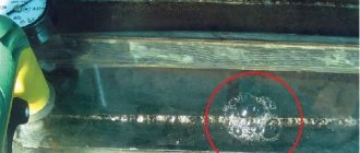
Before marking, carefully check the absence of cracks, cavities or other defects on the workpiece, as well as the possibility of manufacturing a part of the required size from the workpiece. Then the surfaces of the workpieces are cleaned, degreased and painted so that the marking marks are clearer (Table 1).
When marking spatially, the workpiece is placed on a cast iron marking plate. With the help of
1. Cleaning method and painting material depending on the surfaces of the parts to be marked
Details
Cleaning method
Painting material
CASTINGS AND FORGINGS
Processed small steel and cast iron
Processed large steel and cast iron, aluminum castings Non-ferrous metals, hot-rolled sheets and profiled steel products
Steel scrapers, hand wire brushes (small parts) or power brushes and rotary machines (large parts) Degreasing in 10% caustic soda solution Do not clean
Same
Chalk diluted in water to a milky state, drier (for quick drying), wood glue (50 g per 1 liter of water). Lump chalk
Copper sulfate solution (20-30 g of sulfate per 250 g of water) Nitro paint, nitro enamel
Do not paint
marking prisms, linings, wedge jacks, the part is aligned so that its base or main axis is parallel to the flat surface of the plate (marking).
The position of the workpiece is checked at several points, applying horizontal marks with a height gauge, the scriber of which is set to the required size. Vertical markings are made using bench squares (flat or with a wide base).
When applying straight marks, the ruler or square is pressed tightly against the workpiece with three fingers of the left hand so that there is no gap between them and the workpiece. Using a scriber like a pencil, without interrupting the movement, draw a line of the required length at a time. Curvilinear marks are applied using patterns and a marking compass. The lines along which the processing will be carried out are marked.
The distance between the cores can be 5-150 mm depending on the shape of the mark and the size of the part. On straight lines, cores are placed less frequently, but on curves and lo-
much more often. The point of the punch is set exactly on the mark with a slight inclination away from you. Before striking the striker, the center punch is placed in a vertical position. For punching, hammers weighing 100-150 g are used.
2. STRAIGHTENING, STRAIGHTENING AND BENDING
Straightening is a metalworking operation to eliminate defects in workpieces in the form of concavity, convexity, warping, curvature, etc. The essence of straightening is the compression of the convex layer of metal and the expansion of the concave layer. Straightening is carried out in a cold or heated state of the workpiece, depending on its size and material. Straightening can be done manually or by machine using special rollers or presses. A distinction is made between straightening blanks made of sheet metal, profile metal and pipes.
Manual straightening of sheet blanks is performed on a cast iron or steel plate using special hammers with a spherical striker; blanks made of thin sheets are adjusted with hammers with an inserted striker made of soft metal or with a wooden mallet.
Editing sheets is the most difficult. The sheet is laid on the slab, the places of the convexities are determined with a ruler, the boundaries of which are outlined with chalk. Striking patterns during editing are selected depending on the number of protuberances and their location. If there is one bulge in the middle of the sheet, blows are applied starting from the edge of the sheet towards the bulge, changing the force and location of the hammer blows. When editing a sheet with several convexities, blows begin to be applied from the gap between the convexities, gradually approaching the middle of the convexities.
To straighten the sheet, place it on the slab with the convex side up, supporting it with the left hand, and strike it with the right hand with a hammer. The blows should be frequent, but not strong.
Editing strips curved along an edge is carried out as follows: determine the curvature with a ruler or by eye, marking its boundaries with chalk. The wide surface of the strip is placed on the slab and blows are applied across the strip along the edge of the concave side. Stripe one way
Applying marks
The standard regulates the procedure for drawing marking lines:
- horizontal;
- vertical;
- inclined;
- curvilinear.
Applying curved elements after straight ones provides another opportunity to check their accuracy. The arcs must close the straight lines, the interface must be smooth.
Direct marks are carried out with a well-sharpened scriber, without tearing off, in one step. At the same time, the scriber is tilted away from the ruler or square so as not to introduce distortions.
Parallel lines are drawn using a square and moving it along the reference ruler to the required distance.
If the workpiece already has holes, then a special tool, a center finder, is used to attach marking lines to them.
In order to mark inclined lines, use a marking protractor with a hinged ruler fixed at its zero point.
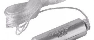
For particularly precise markings in plumbing, calipers are used. They allow you to measure distances and scratch marks with an accuracy of hundredths of a millimeter.
In order to more accurately carry out the risk, cores are placed at its beginning and end. This allows you to visually control the position of the ruler while drawing.
On long risks, auxiliary cores are also placed every 5-15 cm.
Circle lines are marked at four points - the ends of perpendicular diameters.
If already treated surfaces are marked, then punching is used only at the beginning and end of the marks.
After finishing, the marks are extended to the side surfaces and the cores are placed on them.
Marking techniques
The following techniques are used in plumbing:
- According to the template. Used in case of small-scale production. The template is made from rolled metal, the entire batch is marked (or even processed) through once marked slots and holes in this sheet. For parts with complex shapes, several templates can be made for different planes.
- Following the example. The dimensions are transferred from the part - the sample. It is used in the manufacture of a new part to replace a broken one.
- Local. Used in the production of complex multi-component products and structures. Blanks are placed on a plane or in space in the order in which they enter the final product and are marked together.
- Pencil (or marker). Used for workpieces made of aluminum alloys so that the scriber does not destroy the passivated protective layer.
- Accurate. It is done using the same methods, but measurements and special precision are used.
The selection of techniques is carried out in accordance with design and technological instructions.
First of all, when marking, defects that were made at previous stages of production emerge. Products from procurement sites or workshops, as well as materials purchased from other enterprises, reveal:
- violation of dimensions
- shape distortion
- warping.
Such castings or rentals are not subject to further marking operations, but are returned to the department or organization that caused the defect to correct it.
At the marking stage itself, defects can be caused by the following factors:
- Inaccurate drawing. The mechanic, without hesitation, displays incorrect dimensions on the part, and during further processing, defective products come out.
- Inaccuracy or malfunction of instruments. All marking tools are subject to mandatory periodic verification by the metrological service of the enterprise or an authorized metrological center.
- Incorrect use of tools or marking accessories. There are known cases when instead of calibrated measuring pads, ordinary pads were used to set the level. In this case, erroneous application of angles and slopes is also possible.
- Inaccurate placement of the workpiece on the marking table or plaza. They lead to distortions when setting aside dimensions, violation of parallelism and coaxiality.
- Wrong choice of reference planes. It is also possible that some of the dimensions were applied from the base planes, and some from the rough surfaces of the workpiece.
Separately among the reasons for defects are the marker's errors. These include:
- Incorrectly read drawing. It is possible to apply a radius instead of a diameter and vice versa, inaccurate application of the centers of holes relative to the center marks, etc. If any difficulties arise, the mechanic must seek clarification from the foreman or foreman.
- Carelessness and inattention when punching and drawing lines.
The human factor, unfortunately, is the most common cause of marking defects.
Negligence can be committed by both the mechanic himself and his supervisors, who did not check the tool on time or issued inappropriate marking devices.
Typically, marking operations are entrusted to the most experienced and responsible workers, counting on the fact that they will not mechanically transfer dimensions from the drawing to the workpiece, but will treat the matter thoughtfully and promptly notice and eliminate the reasons for possible defects on their own or by contacting their managers.
In order to increase labor productivity, innovative mechanics use improved marking techniques and special devices.
Template marking
It is usually used in the manufacture of large batches of parts of the same shape and size, but sometimes even small batches of complex products are marked using this method.
Figure 3.3.4.1 Marking using a template (B. S. Pokrovsky V. A. Skakun “Plumbing” Moscow 2003)
Templates are made from thick sheet material. 0.5...1 mm, and for parts of complex shapes or with holes - 3...5 mm thick. When marking, the template is placed on a painted workpiece (part) and drawn with a scriber along the contour of the template, after which the score is marked. Using templates, it is convenient to mark holes for drilling, since this eliminates the need for geometric constructions - dividing segments and circles into parts, etc. .
The holes are marked according to the template using a scriber or center punch.
Sometimes the template serves as a guide, according to which the part is processed without marking. To do this, it is placed on the workpiece, then holes are drilled and the side surfaces are processed.
The feasibility of using a template is that marking work, which takes a lot of time, is performed only once when making the template. All subsequent marking operations represent only copying of the template outline.
Marking templates can also be used to control the part after processing.
Marking according to the sample
differs in that it does not require the manufacture of a template. This method is widely used during repair work, when dimensions are taken directly from a failed part and transferred to the material being marked. This takes wear and tear into account.
Marking in place
More often used when assembling large parts. One part is marked on the other in the position in which they should be connected.
Marking with a pencil
It is produced on a line on blanks made of aluminum and duralumin. It is not allowed to mark the latter using a scriber, since when marks are applied, the protective layer is destroyed and conditions are created for the appearance of corrosion.
Accurate markings
performed according to the same rules as usual, but more precise measuring and marking tools are used. The surfaces of the marked workpieces are thoroughly cleaned and covered with a thin layer of copper sulfate solution. It is not recommended to use chalk for painting, as it wears off quickly, sticks to your hands and contaminates the instrument.
When applying marks, they use a gauge with an accuracy of 0.05 mm, and the installation and alignment of the workpieces is carried out using an indicator. More accurate installation can be done by using plane-parallel length measures (tiles) and securing them in special holders. The marks are made shallow, and punching is done with a sharpened center punch with three legs located at an angle of 90° to each other.
The markings must exactly correspond to the dimensions indicated on the drawing; Marking marks must be clearly visible, not erased during processing of the workpiece, not deteriorate the appearance and not reduce the quality of the part, i.e. the depth of the marks and core recesses must meet the technical requirements.
Marking is the operation of applying marking lines to the workpiece being processed, defining the contours of the future part or place to be processed. The accuracy achieved with conventional marking methods is approximately 0.5 mm.
Planar
marking, usually performed on the surface of flat parts, on strip and sheet material, consists of applying contour parallel and perpendicular lines (scores), circles, arcs, angles, axial lines, various geometric shapes according to given dimensions or contours of various holes according to templates to the workpiece .
Spatial
marking is most common in mechanical engineering; and in its techniques it differs from the planar one.
Devices for planar marking
To carry out markings, marking plates, pads, rotating devices, jacks, etc. are used.
The parts to be marked are installed on the marking plate and all fixtures and tools are placed. The marking plate is cast from fine-grained gray cast iron.
The size of the slab is chosen so that its width and length are 500 mm greater than the corresponding dimensions of the workpiece to be marked. The surface of the stove must always be dry and clean. After work, the slab is swept with a brush, thoroughly wiped with a rag, greased with oil to protect against corrosion and covered with a wooden shield.
Tools for planar marking
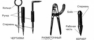
Scribler, caliper, center punch, ruler, square, hammer, etc.
Scribblers are used to draw lines (scores) on the surface to be marked using a ruler, square or template. Scribblers are made from tool steel U10 or U12, sharpened to a cone at an angle of 15-20 0.
Kerner -
a metalworking tool used for making indentations (cores) on pre-marked lines.
Cores are made from tool carbon or alloy steel U7A, U8A, 7HF or 8HF, at an angle of 50-60 degrees.
Compasses
used for marking circles and arcs, dividing segments and circles, as well as for geometric constructions. Compasses are also used to transfer dimensions from measuring rulers to a part.
Reismus is the main tool for spatial marking and is used for drawing parallel, vertical and horizontal lines, as well as for checking the installation of parts on the slab.
Preparing for marking.
Before marking, you must do the following:
Clean the workpiece from dust, dirt, scale, traces of corrosion with a steel brush, etc.;
Carefully inspect the workpiece;
If shells, bubbles, cracks, etc. are detected, measure them accurately and, drawing up a marking plan, take measures to remove these defects during further processing (if possible);
All dimensions of the workpiece must be carefully calculated so that after processing there are no defects left on the surface;
Study the drawing of the part to be marked, find out its features and purpose;
Specify dimensions;
Determine the base surfaces of the workpiece from which dimensions should be taken during the marking process;
When planar marking, the bases can be the processed edges of the workpiece or the center lines, which are applied first;
It is also convenient to take tides, bosses, and plates as bases.
Applying marking marks.
Marking marks are applied in the following sequence: first, horizontal ones are made, then vertical ones, after that - inclined ones, and lastly - circles, arcs and roundings.
Direct marks are applied with a scriber, which should be tilted in the direction of its movement and away from the ruler. The scriber is constantly pressed against the ruler, which should fit tightly to the part. Risks are carried out only once. If the mark is applied poorly, paint over it, let the dye dry, and apply the mark again. Angles and slopes are marked using protractors, calipers, and inclinometers.
Marking marking lines.
A core is a depression (hole) formed by the action of the tip of a center punch when it is struck with a hammer. The centers of the punches must be located exactly on the marking lines.
Marking hammers.
For marking work, use hammer No. 1 (weighing 200 g).
Marking methods.
Template marking is usually used in the production of large batches of parts of the same shape and size, but sometimes even small batches of complex products are marked using this method.
Marking with a pencil
It is produced on a line on blanks made of aluminum and duralumin. It is not allowed to mark the latter using a scriber, since when marks are applied, the protective layer is destroyed and traces of corrosion appear.
Defects:
Inconsistency between the dimensions of the marked workpiece and the drawing data due to the inattention of the marker or the inaccuracy of the marking tool;
Inaccuracy of setting the gauge to the required size; the reason for this is the inattention or inexperience of the marker, the dirty surface of the slab or workpiece;
Careless installation of the workpiece on the slab as a result of slab alignment.
Safety.
Observe the following occupational safety rules:
Installing workpieces (parts) on the stove and removing them from the stove must be done only with gloves;
Workpieces (parts) and fixtures should be securely installed closer to the middle;
Before installing workpieces (parts), check the slab for stability;
Check the reliability of the hammer on the handle;
Remove dust and scale from the marking plate only with a brush, and from large plates - with a broom.
Marking
- the operation of applying marking lines (marks) to the workpiece being processed, which determine the contours of the future part or place to be processed. The marking accuracy can reach 0.05 mm. Before marking, it is necessary to study the drawing of the part to be marked, find out the features and dimensions of the part, and its purpose. The marking must meet the following basic requirements: exactly match the dimensions indicated on the drawing; Marking lines (marks) must be clearly visible and not erased during processing of the workpiece. To install the parts to be marked, marking plates, pads, jacks and rotating devices are used. For marking, scribers, punches, marking calipers and surface planers are used. Depending on the shape of the blanks and parts to be marked, planar or spatial (volumetric) markings are used.
Planar marking
performed on the surfaces of flat parts, as well as on strip and sheet materials. When marking, contour lines (marks) are applied to the workpiece according to specified dimensions or templates.
Spatial marking
most common in mechanical engineering and differs significantly from planar. The difficulty of spatial marking is that it is necessary not only to mark the surfaces of the part located in different planes and at different angles to each other, but also to link the markings of these surfaces with each other.
Base
- a base surface or baseline from which all dimensions are measured when marking. It is selected according to the following rules: if the workpiece has at least one machined surface, it is selected as the base; If there are no machined surfaces on the workpiece, the outer surface is taken as the base surface.
Preparing blanks for marking
begins with cleaning it with a brush from dirt, scale, and traces of corrosion. Then the workpiece is cleaned with sanding paper and degreased with white spirit. Before painting the surface to be marked, you must make sure that the part is free of holes, cracks, burrs and other defects. To paint the surfaces of the workpiece before marking, use the following compositions: chalk diluted in water; ordinary dry chalk. Dry chalk is used to rub the marked untreated surfaces of small non-critical workpieces, since this coloring is fragile; copper sulfate solution; alcohol varnish is used only for precise marking of the surfaces of small products. The choice of coloring composition for application to the base surface depends on the type of workpiece material and the method of its preparation: the untreated surfaces of workpieces made of ferrous and non-ferrous metals obtained by forging, stamping or rolling are painted with an aqueous solution of chalk; the treated surfaces of ferrous metal workpieces are painted with a solution of copper sulfate, which, when interacting with the workpiece material, forms a thin film of pure copper on its surface and ensures clear identification of marking marks; the treated surfaces of non-ferrous metal workpieces are painted with quick-drying varnishes.
Marking methods
Template marking is used in the production of large batches of parts of the same shape and size, and sometimes for marking small batches of complex workpieces. Marking according to a sample is used during repair work, when dimensions are taken directly from a failed part and transferred to the material being marked. This takes wear and tear into account. A sample differs from a template in that it has a one-time use. Marking in place is carried out when the parts are mating and one of them is connected to the other in a certain position. In this case, one of the parts serves as a template. Markings with a pencil are made using a ruler on blanks made of aluminum and duralumin. When marking workpieces made from these materials, scribers are not used, since when marks are applied, the protective layer is destroyed and conditions are created for corrosion. Defects in marking, i.e. Non-compliance of the dimensions of the marked workpiece with the data in the drawing occurs due to the inattention of the marker or the inaccuracy of the marking tool, or a dirty surface of the slab or workpiece.
Metal cutting.
Metal cutting
is an operation in which excess layers of metal are removed from the surface of the workpiece or the workpiece is cut into pieces. Chopping is carried out using cutting and impact tools. The cutting tools for chopping are a chisel, a crosspiece and a groover. Percussion tool - plumber's hammer. Purpose of cutting: - removing large irregularities from the workpiece, removing hard crust, scale; — cutting out keyways and lubrication grooves; — cutting edges of cracks in parts for welding; — cutting off the heads of rivets when removing them; - cutting holes in sheet material. — cutting of rod, strip or sheet material. The cutting can be fine or rough. In the first case, a layer of metal 0.5 mm thick is removed with a chisel in one pass, in the second - up to 2 mm. The processing accuracy achieved when cutting is 0.4 mm.
Editing and straightening.
Editing and straightening
— operations for straightening metal, blanks and parts with dents, waviness, curvature and other defects. Straightening can be done manually on a steel leveling plate or cast iron anvil and machine straightening on straightening rollers, presses and special devices. Manual straightening is used when processing small batches of parts. Enterprises use machine editing.
Flexible.
Bending
- an operation as a result of which the workpiece takes the required shape and dimensions due to stretching of the outer layers of metal and compression of the inner ones. Bending is performed manually using hammers with soft strikers on a bending plate or using special devices. Thin sheet metal is bent with mallets, wire products with a diameter of up to 3 mm are bent with pliers or round nose pliers. Only plastic material is subject to bending.
Cutting.
Cutting (cutting)
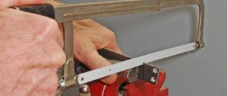
- dividing bar or sheet metal into parts using a hacksaw blade, scissors or other cutting tool. Cutting can be carried out with or without chip removal. When cutting metal with a hand saw, on hacksaw and cutting-off lathes, chips are removed. Cutting materials with manual lever and mechanical scissors, press shears, wire cutters and pipe cutters is carried out without removing chips.
Dimensional processing.
Metal filing.
Filing
- an operation to remove a layer of material from the surface of a workpiece using a cutting tool manually or on filing machines. The main working tools for filing are files, needle files and rasps. Using files, flat and curved surfaces, grooves, grooves, and holes of any shape are processed. The accuracy of filing processing is up to 0.05 mm.
Hole machining
When processing holes, three types of operations are used: drilling, countersinking, reaming and their varieties: drilling, countersinking, counterbore. Drilling
- an operation to form through and blind holes in a solid material. It is performed using a cutting tool - a drill, which makes rotational and translational movements relative to its axis. Purpose of drilling: - obtaining non-critical holes with a low degree of accuracy and roughness class of the machined surface (for example, for fastening bolts, rivets, studs, etc.); — obtaining holes for threading, reaming and countersinking.
Reaming
- increasing the size of a hole in a solid material produced by casting, forging or stamping. If high quality of the machined surface is required, then the hole after drilling is additionally countersinked and reamed.
Countersinking
- processing of cylindrical and conical pre-drilled holes in parts with a special cutting tool - a countersink. The purpose of countersinking is to increase the diameter, improve the quality of the machined surface, and increase accuracy (reducing taper, ovality). Countersinking can be the final machining operation of a hole or an intermediate operation before reaming the hole.
Countersinking
- this is the processing with a special tool - a countersink - of cylindrical or conical recesses and chamfers of drilled holes for the heads of bolts, screws and rivets. Countering is carried out using counterbores to clean the end surfaces. Counters are used to process bosses for washers, thrust rings, and nuts.
Deployment
- This is the finishing of holes, providing the greatest accuracy and surface cleanliness.
Reaming of holes is carried out with a special tool - reamers - on drilling and lathes or manually. Short way https://bibt.ru
Chapter XII
How can you accurately mark a part?
Answer:
Marking according to a template (B. S. Pokrovsky V. A. Skakun “Plumbing” Moscow 2003)
Templates are made from thick sheet material. 0.5...1 mm, and for parts of complex shapes or with holes - 3...5 mm thick. When marking, the template is placed on a painted workpiece (part) and drawn with a scriber along the contour of the template, after which the score is marked. Using templates, it is convenient to mark holes for drilling, since this eliminates the need for geometric constructions - dividing segments and circles into parts, etc. .
The holes are marked according to the template using a scriber or center punch.
Sometimes the template serves as a guide, according to which the part is processed without marking. To do this, it is placed on the workpiece, then holes are drilled and the side surfaces are processed.
The feasibility of using a template is that marking work, which takes a lot of time, is performed only once when making the template. All subsequent marking operations represent only copying of the template outline.
Marking templates can also be used to control the part after processing.
Marking according to a pattern is different in that it does not require making a template. This method is widely used during repair work, when dimensions are taken directly from a failed part and transferred to the material being marked. This takes wear and tear into account.
Marking in place is more often used when assembling large parts. One part is marked on the other in the position in which they should be connected.
Marking with a pencil is made using a ruler on blanks made of aluminum and duralumin. It is not allowed to mark the latter using a scriber, since when marks are applied, the protective layer is destroyed and conditions are created for the appearance of corrosion.
Precise marking is carried out according to the same rules as usual, but more precise measuring and marking tools are used. The surfaces of the marked workpieces are thoroughly cleaned and covered with a thin layer of copper sulfate solution. It is not recommended to use chalk for painting, as it wears off quickly, sticks to your hands and contaminates the instrument.
When applying marks, they use a gauge with an accuracy of 0.05 mm, and the installation and alignment of the workpieces is carried out using an indicator. More accurate installation can be done by using plane-parallel length measures (tiles) and securing them in special holders. The marks are made shallow, and punching is done with a sharpened center punch with three legs located at an angle of 90° to each other.
The markings must exactly correspond to the dimensions indicated on the drawing; Marking marks must be clearly visible, not erased during processing of the workpiece, not deteriorate the appearance and not reduce the quality of the part, i.e. the depth of the marks and core recesses must meet the technical requirements.
Explanation: