Information about the manufacturer of the semi-automatic cylindrical grinding machine 3M151
Manufacturer of semi-automatic cylindrical grinding machine 3M151 , 3M152, 3M162, 3M163 - Kharkov Machine Tool Plant named after. S.V. Kosiora is currently OJSC "Kharkov Machine Tool"
The plant was founded on January 29, 1936 and specializes in the production of universal and special cylindrical grinding machines
Machine tools produced by the Kharkov Machine Tool Plant
- 2B56
radial drilling machine Ø 50 - 3A151
cylindrical grinding machine with hydraulic plunge mechanism Ø 200 x 700 - 3A161
cylindrical grinding machine with hydraulic plunge mechanism Ø 280 x 1000 - 3A164
cylindrical grinding machine Ø 400 x 2000 - 3B151
cylindrical grinding machine Ø 200 x 700 - 3B161
cylindrical grinding machine Ø 280 x 1000 - 3M132v
cylindrical grinding machine Ø 280 x 1000 - 3M151
cylindrical grinding machine Ø 200 x 700 - 3M152
cylindrical grinding machine Ø 200 x 1000 - 3M162
cylindrical grinding machine Ø 280 x 1000 - 3M151F2
CNC cylindrical grinding machine Ø 200 x 700 - 3M193
heavy cylindrical grinding machine with increased precision Ø 560 x 2800 - 3M194
heavy cylindrical grinding machine with increased precision Ø 560 x 4000 - 3M196
heavy cylindrical grinding machine with increased precision Ø 800 x 4000 - 3M197
heavy cylindrical grinding machine with increased precision Ø 800 x 6000 - 3130
cylindrical grinding machine Ø 280 x 700 - 3132
cylindrical grinding machine Ø 280 x 1000 - 3151
cylindrical grinding machine Ø 150 x 750
3M151 universal semi-automatic cylindrical grinding machine. Purpose and scope
3M151 semi-automatic cylindrical grinder is designed for external grinding of cylindrical and conical surfaces of products in single, serial and large-scale production.
With the 3M151 you can perform:
- longitudinal and plunge grinding with manual control;
- longitudinal and plunge grinding in a semi-automatic cycle until it stops and with an active control device for the diametrical size of the product, adjusted to the required grinding diameter.
The change in transverse and longitudinal feeds, as well as the speed of rotation of products on the 3M151 is stepless. The presence of a rolling screw pair in the last link of the transverse feed mechanism in combination with rolling guides ensures micron feed of the grinding headstock. The semi-automatic machine is equipped with a mechanism for balancing the grinding wheel during operation. The roughness of the processed surfaces with the longitudinal grinding method is not lower than V 9, and with the plunge grinding method - V8.
Accuracy of the geometric shape of the processed surfaces: ovality - 0.0032 mm, conicality - 0.008 mm.
Reservoirs for hydraulic system oil and coolant of the 3M151 are located outside the frame.
The headstock spindle is stationary. The product is driven by a DC electric motor through V-belt transmissions, which makes it possible to continuously regulate the rotation of the product.
The spindle of the grinding head is mounted on two sliding bearings of a special design with forced flow lubrication. The grinding head housing is mounted on roller guides.
Diamond dressing of the grinding wheel is carried out using a dressing device mounted on the tailstock, or an automatic dressing device, available on special order for an additional fee.
Modifications of the 3M151 cylindrical grinding machine
Machines of models 3М151 , 3М152, 3М162, 3М163 and 3М164 are of high precision, and machines of models 3М151В, 3М1152В and 3М163В are of high precision.
The basic machines are models 3M151 and 3M162. Machines of models 3M151V, 3M152, 3M152V are modifications of model 3M151, machines of models 3M163, 3M163V, 3M164 are modifications of model 3M162. They differ from the basic models in the length of the installed product.
The machines can be used in small-scale, serial and large-scale production.
The semi-automatic machine model 3M151F2 is equipped with a wide-range active control measuring device, which automatically adjusts when switching from one grinding diameter to another. The measuring device monitors smooth grinding surfaces. Grinding of discontinuous surfaces is carried out using a sensor-converter, which controls the movement of the grinding head.
The semi-automatic machine provides dimensional accuracy according to the 6th quality, the height of micro-irregularities of cylindrical surfaces Ra = 0.32 microns, end surfaces Ra = 1.25 microns.
Methods and features of cylindrical grinding
External cylindrical grinding of workpieces such as bodies of rotation can be carried out using longitudinal working strokes, plunges and ledges.
Grinding with longitudinal working strokes (Fig. 41, a). The workpiece 2 to be ground, rotating on fixed centers, makes longitudinal movement along its axis with a feed Spr (mm/min). At the end of the double or each pass, the grinding wheel 1 is fed in the direction perpendicular to the axis of the workpiece 2, to the set grinding depth or transverse feed SP, equal to the grinding depth t. This method is advantageous for grinding workpieces with a long cylindrical surface. The grinding depth is chosen to be no more than 0.05 mm.
Deep-feed grinding (Fig. 41, b) as a type of grinding with longitudinal feed of a wheel is used when processing hard short workpieces with an allowance of up to 0.4 mm removed in one pass. The main cutting work is performed by the conical part of the circle, and its cylindrical part only cleans the surface of the workpiece. Thus, during creep feed grinding, rough grinding and finishing grinding are combined.
Sometimes grinding is used with two wheels installed side by side, and the wheel for rough grinding is chosen with a larger grain and greater hardness than the wheel for fine grinding. To make it easier to straighten the first circle, a spacer 5-6 mm thick is installed between the circles. When deep-feed grinding requires complete removal of the wheel from the workpiece being ground.
Plunge grinding (Fig. 41, c) is used for rough and fine grinding of cylindrical workpieces. Grinding is carried out with one wide circle, the height of which is 1 - 1.5 mm greater than the length of the surface being sanded. The workpiece has no longitudinal feed. The transverse feed of the circle to a given depth is carried out continuously or periodically. To obtain a surface with a smaller deviation in shape and roughness parameter, the circle is given additional axial oscillatory (oscillating) movement (up to 3 mm) to the left and right.
The advantages of processing the workpiece using this method over grinding with longitudinal passes are as follows: the wheel is fed continuously; you can grind shaped workpieces with a profiled grinding wheel; You can install two or three wheels on the spindle and grind several sections of the workpiece at the same time.
Disadvantages of the cutting method: due to high productivity, a large amount of heat is released; the wheel and workpiece heat up more than during conventional grinding, so grinding must be carried out with plenty of cooling; a faster distortion of the geometric shape of the circle occurs, and therefore more frequent editing is required.
Grinding with ledges (Fig. 41, d). This method combines longitudinal and plunge grinding. This method is used when grinding long workpieces. First, one section of the shaft is ground with a transverse feed of the wheel, then the section adjacent to it, etc. During grinding, the edges of the sections overlap each other by 5-10 mm, but the processed surface turns out to be stepped. Therefore, an incomplete allowance is removed at each section. The remaining layer, equal to 0.02-0.08 mm, is removed with two or three quick longitudinal passes.
Step workpieces begin to be ground from steps of larger diameter; with different lengths of steps, the height of the grinding wheel is chosen equal to the length of the smallest step and grinding is carried out with ledges.
Rough grinding to grinding intended to remove a defective layer of material from a workpiece after casting, forging, stamping, rolling and welding.
When finishing grinding, in contrast to rough grinding, the goal is to achieve the required shape and roughness parameters of the ground surface. Dividing grinding operations into rough and fine grinding makes it possible to increase the productivity of grinding machines and to use less precise equipment for rough grinding. If rough and finish grinding is carried out on precision machines, it is necessary to use reduced feed rates during rough grinding to maintain the accuracy of the grinding machine.
Center cylindrical grinding machines are divided into simple, universal and special.
On simple cylindrical grinding machines, it is possible to rotate the upper table at an angle a = 6°, which makes it possible to grind cones with a small apex angle.
On universal cylindrical grinding machines, in addition to rotating the upper table, it is possible to rotate both the workpiece being ground and the grinding wheel. This makes it possible to grind cones with a large apex angle and end surfaces on machines.
For the manufacture of parts with complex profiles, special semi-automatic and automatic machines . In mechanical engineering, various parts with complex profiles are used, for example, crankshafts and camshafts, multi-spline shafts, gears, ball and roller bearing rings, and shaped cutting tools.
Cylindrical grinding machines are characterized by the largest diameter and length of the workpiece being ground. For general-purpose machines, the largest diameter of the workpiece to be ground is 100–1600 mm, and the largest length is 150–12,500 mm. General purpose cylindrical grinding horizontal centering machines, including CNC machines, with rotary and non-rotary grinding and headstocks, are designed for longitudinal and plunge grinding.
Using a numerical control system - CNC
On the basis of the model under consideration, the creation of a 3m151F2 machine, which has software control, is being created. In this case, the headstock moves under the control of a given program. The presence of program control did not bring significant changes to the design. It consists of the following elements:
- front, rear, grinding headstock;
- a device that is associated with moving the table;
- straightening device;
- a device used to control structural elements during manual operation or when setting up a system.
The only difference is the presence of a device that is responsible for entering the program and adjusting it. The difference also lies in the type of transverse and longitudinal feed mechanisms.
Finally, let us remind you that 3m151 is rarely found on sale due to the emergence of modern versions. Old production technologies that were used to create equipment create low reliability. At the same time, the possibility of repairing the structure is great, but finding the necessary parts is very, very difficult.
If you find an error, please select a piece of text and press Ctrl+Enter.
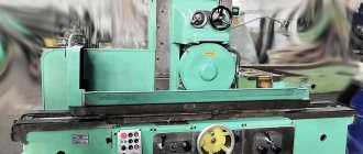
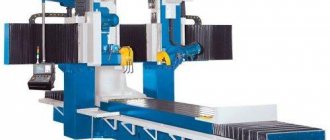
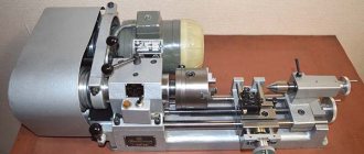
General view of the 3M151 cylindrical grinding machine
Photo of cylindrical grinding machine 3m151
Photo of cylindrical grinding machine 3m151
Photo of cylindrical grinding machine 3m151
Photo of cylindrical grinding machine 3m151
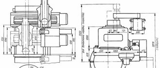
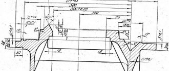
Landing and connecting bases for cylindrical grinding machine 3151
Work table of cylindrical grinding machine 3151
Mounting the grinding wheel of the cylindrical grinder 3151
End of grinding spindle of cylindrical grinding machine 3151
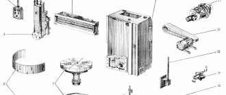
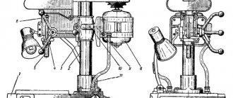
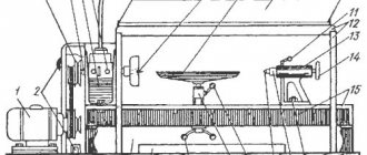
Location of components of the 3M151 grinding machine
Location of the main components of the grinding machine 3m151
List and designation of components of the 3M151 grinding machine
- Bed 3M151.100, 3M162.100
- Electrical equipment 3M151.950
- Table guard 3M151.910
- Headstock 3M151.600
- Steady rest 3M151.870
- Cooling unit 3M151.850
- Grinding head 3M151.200
- Cross feed mechanism 3M151.500
- Tailstock 3M151.700
- Oil line 3M151.800
- Hydraulic control 300
- Manual table movement mechanism 3M151.400
- Mechanism for quick approach of the grinding head 3M151.920
- Mechanism for balancing the grinding wheel SHU-297
Application of a numerical control system - CNC
On the basis of the model under consideration, a 3m151F2 machine is being created, which has software control. In this case, the headstock moves under the control of a given program. The presence of program control did not bring major changes to the design. It consists of the following elements:
- front, rear, grinding head;
- a device that is associated with moving the table;
- straightening device;
- a device that is used to control structural elements when working manually or when setting up a system.
Location of controls for the 3M151 grinding machine
Location of controls for grinding machine 3m151
Control panel for grinding machine 3m151
List of controls for the 3M151 grinding machine
- Input circuit breaker
- Handle for turning on the automatic feed of the grinding head
- Dial for setting allowance for finishing grinding
- Dial for setting the total amount of allowance for grinding
- Coolant release handle
- Lamp switch
- Hard stop activation handle
- Manual cross feed handwheel
- Cross feed dial clamp screw
- Rough feed speed control knob
- Finish feed speed control handle
- Remote Control
- Tailstock quill clamp handle
- Handle for manual retraction of the tailstock quill
- Tailstock quill tension adjustment handle
- Hydropanel
- Tailstock quill hydraulic release pedal
- Flywheel for manual table movement
- Upper table rotation screw
- Signal lamp "Network on"
- Signal lamp "Lack of lubrication" of the spindle bearings of the grinding headstock
- Signal light "Forced feed"
- Signal light "Rough feed"
- Signal light "Finish feed"
- Signal light "Nursing"
- Checking the serviceability of signal lamps
- Product speed indicator
- Grinding wheel drive motor load indicator
- Machine operation cycle switch (adjustment - semi-automatic)
- Switch to start and stop rotation of the product
- Grinding method switch (longitudinal, plunge grinding)
- Manual cross feed clutch switch (on/off)
- Grinding type switch (with active control device - all the way)
- Feed rate adjustment switch (feed off, boost feed, roughing feed, finishing feed, feed off)
- Periodic feed switch (feed every table move, left feed, right feed)
- Switch for the number of nursing strokes
- Product rotation speed regulator for rough grinding
- Regulator of product rotation speed during finishing grinding
- Starting the grinding wheel
- Starting rotation of the product
- Turning off product rotation
- Moving the grinding head forward
- Moving the grinding head back
- General stop
- Starting the hydraulic pump
- Push micron feed
- Regulator of the time relay for curing during plunge-cut grinding
- Table reverse lever
- Throttle for regulating the speed of hydraulic movement of the table during rough grinding
- Handle for quick approach (tilt the handle toward you), retract (tilt the handle away from you) of the grinding headstock, start moving the table from the hydraulic drive when grinding (towards you and to the right) and dressing the wheel (towards you and to the left), moving the table to the right (away from you and to the left) to the right) and to the left (away from you and to the left) with the grinding head retracted
- Throttle for regulating the speed of hydraulic movement of the table during finishing grinding
- Throttle for regulating the speed of hydraulic movement of the table when straightening
- Table reverse delay control throttle on the left
- Table reverse delay control throttle on the right
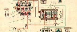
Kinematic diagram of the 3M151 cylindrical grinding machine
Kinematic diagram of the 3m151 cylindrical grinding machine
Through a series of kinematic chains (Fig. 6), the following movements are carried out in the machine:
- rotation of the spindle of the grinding head;
- product rotation;
- manual cross feed of the grinding head;
- automatic cross feed of the grinding head;
- manual table movement;
- automatic table movement;
- manual and hydraulic supply and removal of the tailstock quill.
The grinding wheel is driven by an asynchronous electric motor 17 of three-phase alternating current; transmission of rotation from the electric motor to the spindle of the grinding headstock is carried out by pulleys 18-19 through V-belts.
The product is driven by a thyristor-controlled DC electric motor, which ensures stepless control of the product’s speed over the entire operating range. The transmission of rotation from the electric motor 32 to the faceplate is carried out by V-belts through pulleys 29, 30, 31, 33. The belts are tensioned by turning the eccentric shaft 34 with a toothed rim through a worm 35 and a tension roller.
Manual movement of the table is carried out by rotation of the flywheel 42, which is transmitted through spur gears 38, 40, 41, 43 and clutch 37 to gear 27, coupled with rack 28, mounted on the lower table of the machine.
Two speeds of manual movement of the table are possible—3.1 and 20.4 mm per revolution of the flywheel.
To obtain greater speed, you should move the flywheel 42 in the axial direction away from you, thereby engaging the gears 43 and 41 (the position shown in the diagram) and rotate it; to obtain a lower speed, the flywheel must be moved towards itself, as a result of which gears 44 and 39 are brought into mesh.
In order to ensure operational safety, the manual movement mechanism of the table is interlocked with the hydraulic movement system of the table. When the latter is turned on, the clutch 37 is automatically released by the hydraulic plunger 36, as a result of which the rotation of the rack and pinion gear 27 is not transmitted to the flywheel for manual movement of the table.
The tailstock quill 10 with a gear rack cut into it can be brought to the product to secure it in the centers or retracted to unload the product from the machine with a handle connected to gear 14. The quill can also be removed hydraulically: when oil enters under pressure into the hydraulic cylinder 16, the piston -rack 15 starts to move and, turning gear 14, moves the quill away from the product, overcoming the force of spring 11. The force of pressing the quill to the product (it is carried out by spring 11) is adjusted by a screw pair 12-13.
Manual feed of the grinding headstock is carried out by a flywheel 9, the rotation of which is transmitted through a conical pair 6-7 and a worm pair 24-21 to the ball nut 21 of the feed screw 20.
The machine has automated plunge-cut and longitudinal grinding cycles. The mechanisms for periodic and plunge feeds, as well as for moving the grinding headstock, operate from a hydraulic drive, using a worm pair 2-8, a cylindrical pair 5-25, hydraulic motors 3 and 26 and electromagnetic couplings 1, 4. A description of the feed mechanism for the grinding headstock is given in the sections “Design and operation of the machine and its main parts. Cross feed mechanism" and "Hydraulic system".
The design and operation of the table hydraulic movement system is described in the “Hydraulic System” section.
Key Features
There are quite a few different designs of cylindrical grinding machines that allow processing of cylindrical and conical surfaces. The version with a 3M151 grinding head is used quite often; the passport indicates all the important technical characteristics, and the diagram also indicates important points about the location of structural elements.
Download the passport of the grinding machine 3M151
Cylindrical grinding machine model 3M151 is used for processing the outer cylindrical surface. Shaft-type products are often processed on the 3M151 machine. In this case, conical workpieces can also be processed while the grinding headstock is displaced. The machine passport contains information about how conical the surface can be. It is worth noting that the cylindrical grinding machine model 3M151 has increased accuracy. When using it, you can carry out the following types of work:
- The design scheme makes it possible to carry out longitudinal and transverse grinding using manual feed. the passport indicates the maximum longitudinal and transverse manual feed;
- model 3m151 can be used for plunge-cut and longitudinal grinding in a semi-automatic operating cycle;
- Some versions have a system for entering a workpiece processing program; the work is carried out automatically.
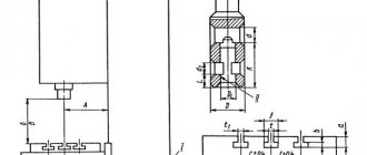
Design of the 3M151 cylindrical grinding machine
Machine bed and tables
A lower table 9 is installed on the longitudinal guides of the front part of the frame (Fig. 7), which carries an upper rotary table 8. When grinding cones, the upper table must be rotated to the required angle using a screw 4 relative to the spherical ball bearing 23 and secured with clamps 3 and 10 .
Clamp 3 is equipped with a scale for approximate table alignment and indicator device 2 for precise adjustment of the angle of rotation of the upper table.
Manual movement of the lower table along the frame guides is carried out by rotating the flywheel (Fig. 6) through a mechanism, the gear of which engages with rack 24 fixed to the lower table.
To move the table from the hydraulic drive, a cylinder 17 is provided, the shoes 15 of which on machines models 3M151, 3M151V, 3M152, 3M152V (see section B-B, model 3M151, Fig. 7) are fixed to the frame. The piston rods 14 of this cylinder are connected to the lower table (the right cylinder shoe and the piston rod are not shown in the figure). On machines models 3M162, 3M163, 3M163V and 3M164, the hydraulic cylinder 22 for moving the table is secured by shoes 21 on the lower table, and the hollow piston rods 20 are connected to the frame by brackets 18 (see section B-B, model 3M162). When the table moves hydraulically, oil enters the cylinder through the holes of these rods.
Stops 7 are fixed in the T-shaped groove of the lower table, the position of which determines the length of the table stroke when working with automatic reverse.
An indicator device 6 of a folding type is fixed on the front wall of the bed, which is affected by a stop 5, which, if necessary, is fixed in the T-shaped groove of the table, which allows you to count the fine longitudinal movements of the lower table when grinding the end surfaces of the product with the end of the wheel.
A backing plate 11 is mounted on the rear part of the frame, on the transverse guides of which a grinding headstock is installed with roller tires 12. A mechanism for quick supply of the grinding head is mounted in the backing plate.
Pedal 13 produces hydraulic retraction of the tailstock quill.
Grinding head
The design of the grinding head of machines models 3M151, 3M151V, 3M152, 3M152V is shown in Fig. 8, and the design of the grinding head of machines models 3M162, 3M163, 3M163V, 3M164 is shown in Fig. 9.
The spindle 7 of the grinding headstock is mounted in two hydrodynamic plain bearings. The bearing shells 9 have the shape of segments that cover the spindle journals, and with their spherical holes rest on the ball-head screws 8, which allows them to self-align along the spindle journals. The design of the liners ensures the formation of oil wedges between them and the spindle journals during operation, which increases the wear resistance of the spindle assembly of the grinding head and prevents excessive heating of the bearings.
Cross feed mechanism
The cross-feed mechanism mounted on the grinding headstock body (Fig. 10 and 11) allows the following movements:
- manual cross feed of the grinding head;
- fast installation movement of the grinding head;
- automatic continuous and periodic feeding of the grinding head;
- jog feed of the grinding headstock.
In addition, using this mechanism, the following is carried out:
- setting the amount of allowance for grinding;
- automatic switching from roughing to finishing feeding;
- manual compensation of grinding wheel wear.
Machine design
Bed and tables
The machine bed consists of two parts: front and rear. The table moves along the guides in the front part in the longitudinal direction.
The upper part of the table is rotatable, which makes it possible to grind conical-shaped parts. On the top of the table there are headstocks and tailstocks for placing the part to be sanded between them. The guides at the rear of the frame are used for transverse movement of the grinding headstock. To install the upper part of the table when grinding conical or cylindrical parts, there is a turning mechanism with a dial and pointer on the right side of the table (Fig. 163). Using the dial and pointer, approximately set the angle of rotation of the upper part of the table. To accurately set the table to the required angle, do the following: loosen the clamps, rotate the screw to move the upper part of the table, and then fix it in the desired position and grind the surface with a very small depth of cut. Having measured the dimensions of the grinded shaft at its ends, the angle of rotation of the upper part of the table is adjusted based on the measurement results if it turns out to be incorrect. After establishing the required angle of rotation of the table, the final fastening of the table clamps and grinding is carried out.
Hydraulic diagram of the 3M151 cylindrical grinding machine
Hydraulic diagram of cylindrical grinding machine 3m151
The hydraulic system of the machines (Fig. 23 and 24) performs the following functions:
- longitudinal movement of the table with automatic reverse at the end of the stroke;
- speed-regulated table movement with the grinding head retracted;
- quick approach and removal of the grinding head;
- installation run of the grinding head;
- retraction of the tailstock quill with the grinding head retracted;
- blocking the mechanism for manual movement of the table;
- continuous forced feed of the grinding headstock until the wheel touches the workpiece;
- roughing and finishing transverse feeds of the grinding headstock (continuous during plunge grinding and periodic during longitudinal grinding);
- push microfeed of the grinding headstock;
- automatic retraction of the grinding head after obtaining the specified size of the workpiece;
- sending commands to the electric counter of table moves during nursing;
- recharging the feed mechanism of the grinding headstock;
- blocking the table start during plunge-cut grinding;
- lubrication of spindle bearings of the grinding headstock;
- lubrication of table guides;
- lubrication of the cross feed mechanism screw support;
- lubrication of the worm pair of the cross feed mechanism.
The designations of the connection numbers on the hydraulic circuits of the machines correspond to the numbers stamped on the panels and intermediate brackets.
The main pumping unit of the machine's hydraulic system, the table guide lubrication pump, the grinding head spindle bearing lubrication pump and most of the control equipment are located in a complete hydraulic drive station located near the machine.
The table reverse hydraulic panel, control valve and throttles that regulate the speed of table movement are located in the window of the front wall of the frame. The throttles that regulate the speeds of roughing and finishing feeds of the grinding headstock are located on the cross feed mechanism.
The main pumping unit consists of a twin vane pump with a capacity of 12+18 l/min, installed on the tank cover of the complete hydraulic drive station.
A pump with a capacity of 18 l/min, together with a pump with a capacity of 12 l/min, serves to drive the table, and a pump with a capacity of 12 l/min serves to drive all other movements of the machines.
When the reverse movement of the table is turned on, the pump Q = 12 l/min is included in the power supply system of the table cylinder together with the pump Q = 18 l/min. If the hydraulic movement of the table is not used, then the pump Q = 18 l/min is unloaded to drain through the grooves of the spool 25.7 and then through the heat exchanger 4, where the oil is cooled.
Fine filtration of the oil coming from the pump Q = 12 l/min is carried out by fine filter 11(1), and coarse filtration of all oil by filter 6.
The pressure in the table drive system is adjusted by pressure spool 2, and the pressure in the drive system for feeding and moving the grinding headstock is adjusted by pressure spool 12; both of these pressures are controlled by pressure gauge 8(2), connected to the system through spool 7(2).
All other elements of the machine hydraulic system operate at a lower pressure than the grinding head feed drive system.
Pressure reduction is carried out by pressure reducing valve 9, and pressure control is carried out by pressure gauge 8(1), connected to the system through spool 7(1).
Check valves 5 and 10 protect the system from inertial discharge through the pumps when the hydraulic drive is turned off.
Technical characteristics of the 3M151 machine
| Parameter name | 3M151 | 3M152 | 3M162 | 3M163 |
| Main settings | ||||
| Accuracy class according to GOST 8-82 | P/W | P/W | P/W | P/W |
| Largest diameter of the workpiece, mm | 200 | 200 | 280 | 280 |
| Maximum length of the workpiece, mm | 700 | 1000 | 1000 | 1400 |
| Largest grinding diameter, mm | 200 | 200 | 280 | 280 |
| Smallest grinding diameter, mm | 10 | 10 | 10 | 10 |
| Maximum grinding length, mm | 700 | 1000 | 1000 | 1400 |
| Distance from the axis of the headstock spindle to the table mirror, mm | 125 | 125 | 160 | 160 |
| Maximum mass of the processed product, kg | 55 | 55 | 200 | 200 |
| Cone of the headstock spindle and tailstock quill according to GOST 2847-67 | Morse 4 | Morse 4 | Morse 5 | Morse 5 |
| End of the grinding spindle according to GOST 2323-67 (taper 1:5, nominal diameter), mm | 80 | 80 | 100 | 100 |
| Diameter of the front support journal of the grinding spindle, mm | 90 | 90 | 110 | 110 |
| Distance from the machine sole to the axis of the product, mm | 1060 | 1060 | 1040 | 1040 |
| Machine work table | ||||
| Maximum table movement length, mm | 705 | 995 | 980 | 1400 |
| Manual accelerated movement of the table per revolution of the flywheel, mm | 20,4 | 20,4 | 20,4 | 20,4 |
| Manual slow movement of the table per revolution of the flywheel, mm | 3,1 | 3,1 | 3,1 | 3,1 |
| Minimum table stroke from the hydraulic system, mm | 4,0 | 4,0 | 4,0 | 4,0 |
| Table movement speed from the hydraulic system, m/min | 0,05…5,0 | 0,05…5,0 | 0,05…5,0 | 0,05…5,0 |
| Maximum angle of rotation of the upper table clockwise, degrees | 3° | 3° | 3° | 3° |
| Maximum angle of rotation of the upper table counterclockwise, degrees | 10° | 8° | 8° | 7° |
| Upper table rotation scale division value, deg | 0°40′ | 0°40′ | 0°40′ | 0°40′ |
| Taper, mm/m | 10 | 10 | 10 | 10 |
| Grinding head | ||||
| Grinding wheel according to GOST 2424-67 | PP600 80x305 | PP600 80x305 | PP750 80x305 | PP750 80x305 |
| Maximum height of the installed circle, mm | 100 | 100 | 100 | 100 |
| Grinding head spindle rotation speed, rpm | 1590 | 1590 | 1260 | 1260 |
| Grinding wheel cutting speed, m/s | 50 | 50 | 50 | 50 |
| Maximum movement of the grinding head along the screw, mm | 185 | 185 | 290 | 290 |
| The size of the quick approach of the grinding head, mm | 50 | 50 | 50 | 50 |
| Time for rapid approach of the grinding head, s | 2,5 | 2,5 | 2,5 | 2,5 |
| Maximum periodic feed of the grinding head (stepless regulation), mm | 0,05 | 0,05 | 0,05 | 0,05 |
| Minimum periodic feed of the grinding head (stepless control), mm | 0,0025 | 0,0025 | 0,0025 | 0,0025 |
| The amount of movement of the grinding headstock during grinding, mm | 0,45 | 0,45 | 0,45 | 0,45 |
| Plunge feed speed limits, mm/min | 0,1…4,5 | 0,1…4,5 | 0,1…4,5 | 0,1…4,5 |
| Jog feed, mm | 0,001±0,0005 | 0,001±0,0005 | 0,001±0,0005 | 0,001±0,0005 |
| The amount of transverse movement of the grinding head per one revolution of the flywheel, mm | 0,5 | 0,5 | 0,5 | 0,5 |
| Headstock | ||||
| Product rotation speed (stepless regulation), rpm | 50…500 | 50…500 | 40…400 | 40…400 |
| Tailstock | ||||
| The amount of retraction of the tailstock quill by hand, mm | 35±2 | 35±2 | 35±2 | 35±2 |
| The amount of retraction of the tailstock quill from the hydraulic system, mm | 35±2 | 35±2 | 35±2 | 35±2 |
| Drive and electrical equipment of the machine | ||||
| Number of electric motors on the machine | 8 | 8 | 8 | 8 |
| Grinding head spindle electric motor, kW/rpm | 10/ 1500 | 10/ 1500 | 17/ 1500 | 17/ 1500 |
| Product drive electric motor, kW/rpm | 0,85/ 2200 | 0,85/ 2200 | 1,5/ 2200 | 1,5/ 2200 |
| Hydraulic pump electric motor, kW/rpm | 1,5/ 1000 | 1,5/ 1000 | 2,2/ 1000 | 2,2/ 1000 |
| Electric motor of the lubrication system pump, kW/rpm | 0,27/ 1500 | 0,27/ 1500 | 0,27/ 1500 | 0,27/ 1500 |
| Electric motor of the table guide lubrication system pump, kW/rpm | 0,08/ 1500 | 0,08/ 1500 | 0,08/ 1500 | 0,08/ 1500 |
| Cooling system pump electric motor, kW/rpm | 0,15/ 3000 | 0,15/ 3000 | 0,6/ 3000 | 0,6/ 3000 |
| Magnetic separator electric motor, kW/rpm | 0,12/ 1500 | 0,12/ 1500 | 0,12/ 1500 | 0,12/ 1500 |
| Hydraulic unit fan electric motor, kW/rpm | 0,12/ 3000 | 0,12/ 3000 | 0,12/ 3000 | 0,12/ 3000 |
| Electric motor of the filter-conveyor, kW/rpm | 0,08/ 1500 | 0,08/ 1500 | 0,08/ 1500 | 0,08/ 1500 |
| Overall dimensions and weight of the machine | ||||
| Overall dimensions of the machine (length x width x height), mm | 4605 2450 2170 | 4605 22970 2170 | 5130 2930 2070 | 5370 2930 2170 |
| Weight of the machine with electrical equipment and cooling, kg | 5600 | 6100 | 8100 | 9220 |
- Semi-automatic cylindrical grinders 3M151, 3M151V, 3M152, 3M152V, 3M162, 3M163, 3M163V, 3M164. Operating manual, 1976
- Loskutov V.V. Grinding machines machines, 1988. p. 45
- Alperovich T.A., Konstantinov K.N., Shapiro A.Ya. Design of grinding machines, 1989
- Alperovich T.A., Konstantinov K.N., Shapiro A.Ya. Setup and operation of grinding machines, 1989
- Dibner L.G., Tsofin E.E. Sharpening machines and semi-automatic machines, 1978
- Genis B.M., Doctor L.Sh., Tergan V.S. Grinding on cylindrical grinding machines, 1965
- Kashchuk V.A., Vereshchagin A.B. Grinder's Handbook, 1988
- Kulikov S.I. Honing, 1973
- Lisova A.I. Design, adjustment and operation of metal-cutting machines, 1971
- Loskutov V.V. Metal grinding, 1985
- Lurie G.B. Grinding machines and their adjustment, 1972
- Lurie G.B. Design of grinding machines, 1983
- Menitsky I.D. Universal sharpening machines, 1968
- Mutsyanko V.I. Bratchikov A.Ya. Centerless grinding, 1986
- Naerman M.S., Naerman Ya.M. Guide for training grinders. Textbook for vocational schools, 1989
- Naerman E.S. The Young Grinder's Handbook, 1991.
- Popov S.A. Grinding work, 1987
- Tergan V.S. Grinding on cylindrical grinding machines, 1972
- Shamov B.P. Types and designs of main components of grinding machines, 1965
Bibliography:
Related Links. Additional Information
- Classification and main characteristics of the grinding group
- Repair, restoration and modernization of grinding machines: the American approach
- Cylindrical grinding. Processing on cylindrical grinding machines. Grinding Methods
- Setting up a cylindrical grinding machine when installing parts in centers
- CNC grinding machines
- Marking of grinding wheels
- Testing and checking metal-cutting machines for accuracy
- Grinding machines. Market of grinding machines in Russia
- Manufacturers of sharpening and grinding machines in Russia
- Directory of grinding machines
Home About the company News Articles Price list Contacts Reference information Interesting video KPO woodworking machines Manufacturers
Technical properties
When considering the data in the passport, it is necessary to take into account that there are two or three main technical specificities that determine the possibility of using the equipment. These include:
- the largest criterion for the diameter of the installed product for processing.
- The distance between centers is indicated in the diagram and in the passport. this moment determines the length of the workpiece that can be used;
- the number of revolutions that the workpiece can perform in one minute;
- number of revolutions of the grinding wheel.
Technical properties 3M151
The above points must be taken into account when considering cylindrical grinding machines. The technical properties of the model under consideration include:
- accuracy class according to the necessary GOST standards - P;
- the largest criterion for the diameter of cylindrical products is 200 millimeters;
- the longest length of the installed product is 700 millimeters;
- the minimum grinding diameter is 10 millimeters;
- the height of the product above the table is 125 millimeters;
- the largest workpiece weight is 55 kilograms;
- the longest table movement distance is 705 millimeters;
- the maximum height of the installed circle is 100 millimeters;
- tailstock rotation speed is 1590 rpm.
Download the manual for the 3M151 grinding machine
In addition to this, it is necessary to take into account the dimensions and dimensions of the structure, as well as the heaviest weight. These indicators form the possibility of using the model in different life situations. The weight of the structure is 5,600 kilograms, which makes its positioning difficult. Only if there is a specialized base can the best conditions for the location and fastening of the structure be provided.
Download acceptance manual 3M151