Tool for sharpening cutters
- » rel=»nofollow»>
Details Updated: January 13, 2017 11:03 Author: Aleshkin
Homemade device for sharpening cutters and other cutting tools.
During the operation of our machines, the need for such a device arose.
You can sharpen a drill by hand, but what about cutters, where there are not two, but four, or more edges only at the bottom, and you need a less precise geometry, and the size is small.
So I decided to make such a device.
It's a simple back and forth feed mechanism, plus tilt and swivel.
It will be installed simply next to the sandpaper.
The materials available were aluminum, some steel, and sandpaper.
I will now show you how this was done in photographs.
Let's start with the device that must hold the cutter or drill, that is, the spindle, to install the tool.
To do this, I have such a part in it, Morse taper number two (KM2), this is what I need.
After all, my machines also have KM2 everywhere, and you can use their equipment, and mortises and drills with such a cone can be installed directly into the spindle.
I removed everything unnecessary from this mandrel.
The result is a small spindle that can rotate around its axis.
I'll do a little modification, drill a hole for a cleaning rod, which will secure the tool from suddenly falling out of the spindle.
Now the spindle will be able to accept any tool with KM2, both with a presser foot and with M10 threads, a drill or collet chuck, cutters with KM2 and all kinds of mandrels for disk cutters.
Now the housing for this spindle.
All that remains is to make a locking ring for the spindle and a handle.
Handle for rotation around the spindle axis.
This is what the first assembled part for my device looks like.
Fitting equipment, drill chuck.
Now you can work on the movement mechanism, it will be like a small cross table, similar to that of a milling machine only with rotation around its axis.
I am sawing a blank for the table.
Milling future movement axes.
Preparing a table for installing a spindle.
The workpiece is ready for dovetail milling.
I'm milling a dovetail.
I drill, cut the threads and add an axial movement nut.
I try on the guide for the table; the screw for it will be an ordinary pin.
The propeller supports are made from two small pieces of aluminum.
General view of the finished axle with fitting of the collet chuck.
The general appearance of the device is already emerging, but this is just a project.
I had some free time and I spent it in the workshop, working on the ears or hinges, for the tilt and the turntable with the axis.
So that the loops or ears were the same, I connected them immediately into one piece.
And then I drilled and bored holes for the axle.
I cut off a little excess aluminum and drilled it, then cut a thread for the hinge adjustment screws.
The second axis of movement in the trailer is no different from the first, only there is no feed screw and the table is slightly wider.
A turntable in the shape of an ordinary pancake.
This simple cylinder will serve as my tilt axis.
I tried everything on the table, all that remains is to drill and assemble this unit.
Drilled and assembled.
I assemble two axes into one whole device.
Again we drill and tap the threads for the screws.
I cut out a corner and put a pin on it to read the cutter strip when sharpening.
This is what the entire device looks like assembled.
Over the weekend at the dacha I couldn’t resist and carried out the first tests, tried to level and then sharpen the end of the cutter.
To do this, I secured my homemade device on the table with self-tapping screws, near the sandpaper.
Here is a video report on the experiment.
All that remains is to finalize the sharpening of the cutter strips and make a stop that limits the cutter from falling to the front, and finally, a table for this device.
For those who are interested in this topic, below is a link to the continuation.
How to properly sharpen a cutter for metal: several ways
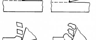
The main task is to process a curved surface of great length on both sides. In this case, the cutting tool is an abrasive substance. It should be directed directly along the edge (at the correct angle).
How to sharpen using a machine
Technologically, this process occurs in several stages:
- Securing the tool in the desired position in the moving part of the bed.
- Bringing the cutting element to the rotating abrasive wheel until uniform sparking appears.
- Trimming a metal layer up to 50 microns wide.
In this case, the following recommendations must be followed:
- Each tooth needs individual sharpening.
- The movement should occur from the beginning of the furrow to the outer edge.
- All cycles must be carried out in the same way to achieve complete uniformity in the cutting edge.
How to sharpen cutters using sharpening wheels
This is special equipment, the nozzle of which is made of an abrasive substance and is a closed belt:
The peculiarity of turning lies in the correct choice of material. What abrasives do they sell:
- White or classic electrocorundum. It is most often used for ordinary wood or metal cutters.
- Elbor – processes high-speed steel well.
- Silicon carbide or diamond (natural, synthetic) copes well with carbide products.
Recommendation: use cooling lubricants to reduce the thermal effect of friction force.
Using improvised means
To do this, you need a homemade device or a table for a hand router.
Algorithm of actions:
- Using a special liquid, it is necessary to clean the surface of the tool from carbon deposits. To do this, you need to place the cutter in a container and leave it there to soak for 3 minutes, then clean it with coarse bristles.
- Using a diamond stone, grind the edge at the front to ensure longitudinal movement.
- Wipe the finished equipment with a soft cloth to remove metal dust.
Machine for sharpening cutters for metal
Nikolay Chernak spoke about a homemade machine that he uses to sharpen end mills for metal. Acquisition history. One Sunday I stopped by a flea market and noticed that a man was selling an interesting machine. As soon as the buyer showed interest, a man immediately came up and said that he also wanted to buy a machine and had been bargaining since the morning. He needs this machine to make wobblers for fishing. He wants to make a copier out of it. Nikolay took this homemade machine for a while to review it.
Technical characteristics of the sharpening machine
When purchasing special equipment, you need to carefully consider the following indicators:
- Power supply from 220 V or 360 V.
- Consumption from 200 to 5000 W.
- The spindle rotates without load at speeds from 900 to 3000 per minute.
- Required accuracy class.
- Abrasive wheel feed speed.
- The drive mechanism can be manual or electric.
- What angle can be achieved.
- Are there containers for water or other coolant?
- Availability of a fan.
- The noise level that the machine creates.
- The quality of the protective casing, its strength.
- Floor or tabletop variety.
Machine Features
Let's look at the capabilities of this machine and what it is intended for. Has length adjustment according to the cutter. That is, you can clamp long cutters. There are many holes and a groove for setting the required length. Emphasis.
One part is missing parts. Judging by the fact that there is a thread cut here, there must be chucks for clamping other cutters. There are not enough collets. There are 16 holes on the outside of the cartridge. There should also be a pin here, insert it tightly and divide by a multiple. Movement by hand, a little tight. Judging by the collet, if you find other sizes, you can install a fairly thick cutter in diameter.
Sharpening machine for straightening circular saw blades: do it yourself
Home craftsmen know that there is no such thing as too many tools. You need everything - from a simple hammer to a lathe for metal or wood. If you don’t have enough money to buy the necessary equipment for your workshop, then the solution is to make what you need yourself from what you have at hand. For example, a machine for pennies for sharpening carbide-tipped disks for a circular saw, following the example of a portal user with the nickname evgenii957.
- How to make a machine for straightening circular saw blades.
- What materials and tools are needed for this?
Do-it-yourself machine for resharpening circular saw blades: without lathe and milling work
I need to sharpen a saw blade from a carbide-tipped circular saw. Difficulties - the teeth have different inclination angles and different sharpening angles for the tips. I decided to make a budget sharpening machine for regrinding discs. I looked at different designs on the Internet. There are homemade products made of metal or wood. It's not the same. Either the design is too complex, or constant dancing with a tambourine to set the required angle of inclination for sharpening the disc. I thought about it and made myself a universal sharpening machine. Moreover, without turning and milling work.
The user happily told how he assembled a machine for straightening discs from scrap parts. Tools you will need:
- electric drill;
- angle grinder;
- tap for cutting M4 threads;
- flat file;
- sandpaper.
The sharpening machine consists of a horizontal movable carriage on which a plate is mounted and a disk is attached, pressed by a wing nut. Saw blades have different tooth angles. Therefore, the plate can move along the radius to more accurately position the saw blade tooth in relation to the sharpening blade.
The carriage stands on a base (bed) in which slots are made.
Important . The table can be tilted left and right. To do this, the user made a metal part like a protractor.
Necessary parts for the manufacture of a sharpening machine for dressing circular saw blades
For the machine you needed:
- Grinding disc with a diameter of 100 mm and a thickness of 1 mm with a mounting hole with a diameter of 2 cm.
- 650 W electric motor.
This engine is already 40 years old. I used it then as a homemade “grinder”. The shaft was extended by welding a metal rod to it. A piece of a bicycle frame with a welded bearing housing is put on the shaft and a rubber handle from a motorcycle is put on. There was a handle at the back. So it came in handy for making a sharpening machine for resharpening circular saw blades.
On the topic of machines and devices for DIYers, we recommend:
The peculiarity of sharpening cutters is the relatively large length and curvilinearity of the cutting edges of their teeth. When sharpening, it is necessary to ensure that the surface of the wheel moves exactly along the edge. Particularly difficult in this regard is the sharpening of shaped cutters that have a backed corner. To maintain the shaped profile of the cutter and simplify sharpening, the backed teeth are sharpened only along the front surface (where the front and where the back surfaces are, see below). Sharpened teeth, having a straight or standardized curved shape, are sharpened along the back surface. Slotting and parting cutters are sharpened along the front and back surfaces of the teeth. Read about sharpening them in the article Sharpening circular saws.
Sharpening cutters
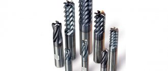
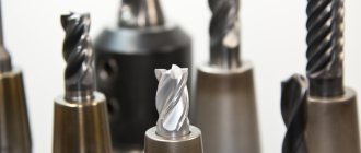
Domestic and foreign manufacturers produce hundreds of types and thousands of standard sizes of all kinds of cutters, which are classified according to technological characteristics and design features.
Milling cutters
The peculiarity of sharpening cutters is the relatively large length and curvilinearity of the cutting edges of their teeth. When sharpening, it is necessary to ensure that the surface of the wheel moves exactly along the edge. Particularly difficult in this regard is the sharpening of shaped cutters that have a backed corner. To maintain the shaped profile of the cutter and simplify sharpening, the backed teeth are sharpened only along the front surface (where the front and where the back surfaces are, see below). Sharpened teeth, having a straight or standardized curved shape, are sharpened along the back surface. Slotting and parting cutters are sharpened along the front and back surfaces of the teeth. Read about sharpening them in the article Sharpening circular saws.
Sharpening is carried out on specialized and universal machines for sharpening cutters, or less often manually.
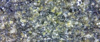
Milling cutter material
For the manufacture of cutters, various materials are used: carbon and alloy tool steels, high-speed tool steels, hard alloys, mineral ceramics, CBN, diamonds.
The types of tool steels used are U7A, U8A, U9A, KhG, KhV5, 9KhS, KhVG, etc.
High-speed tool steel used for the manufacture of cutters is divided into steel of normal productivity (R6M5, R9, R12, R18, etc.) and increased productivity. The last category includes steels alloyed with cobalt, vanadium, tungsten and molybdenum (R6M3, R18F2K5, R9F2K10, R9F2K5, etc.).
The hard alloys from which cutter teeth are made are produced in the form of plates of standard sizes and shapes, attached to the cutter body by high-temperature soldering (for example, PSr-40 silver solder) or using threaded connections (prefabricated cutters). They consist of tungsten, titanium and tantalum carbides bonded with cobalt. Cutters made from tungsten-cobalt alloys (VK2, VK3, VK6, VK6M, VK8, etc.) are used for processing cast iron, non-ferrous metals, and non-metallic materials. Titanium-tungsten-cobalt alloys (T5K10, T15K6, T14K8, T30K4, etc.) are less durable than alloys of the VK type, but they have higher wear resistance when processing parts made of various types of steel. Three-carbide alloys, consisting of tungsten, tantalum, titanium and cobalt carbides (TT7K12, etc.), are also mainly used for processing steels.
If a cutter has cutters made of soldered plates, this does not mean that they are made of hard alloy. They, for example, can be made of high-speed steel.
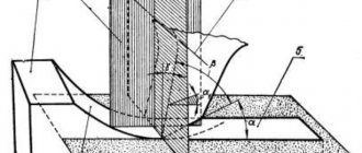
Cutter tooth geometry
Based on the design of the teeth, cutters with pointed (sharpened) and backed teeth are distinguished. For pointed teeth, the part of the rear surface with width f adjacent to the cutting edge is a plane. Pointed teeth are sharpened along the back surface. Although, if necessary, they can be sharpened along the front surface of the tooth.
Geometry of cutter teeth: a - sharpened tooth, b - backed tooth
The back surface of the backed teeth, which are equipped with shaped cutters, follows an Archimedean spiral. Since processing a shaped surface is very difficult technologically, sharpening of cutters with backed teeth is carried out along the front surface.
Regardless of how many teeth there are on the cutter, each of them can be considered as a separate cutter, characterized by standard parameters for any cutter - front (γ) and back (α) angles, the size of the ground area (f), the angle of inclination of the teeth (λ) .
Cutter tooth geometry
Site f
is a part of the back surface of the tooth that is subjected to grinding when sharpening along the back surface. The main wear of the teeth occurs along this surface; its size affects the magnitude of the friction force between the cutter and the workpiece, so it must be maintained within a certain range.
Main rake angle γ
— the angle between the tangent to the front surface and the axial plane. It is measured in a plane that passes through a given point perpendicular to the main cutting edge.
Main clearance angle α
- the angle between the tangent to the rear surface at the considered point of the main cutting edge and the tangent to the circle of rotation of this point. The function of angle α is to reduce friction between the cutter and the workpiece.
Auxiliary relief angle α1
characterizes the increased clearance between the treated surface and the body of the tooth. The need to sharpen cutters at an auxiliary angle arises with a certain amount of cutter wear and an increase in the area f. Its purpose is to reduce friction between the tooth and the material being processed. Not all cutters have this angle.
Depending on the shape and direction of the cutting edge, the teeth can be straight or helical. The inclination of the cutter teeth is characterized by the angle λ
between the deployed helical edge and the axis of the cutter.
The angle values depend on the type of cutter, the grade of alloy or steel from which it is made, and the type of material it is intended for processing.
When processing viscous materials, the main rake angle is selected within 10-20° or more. For carbide cutters for processing steels, it is close to zero or even negative. The clearance angle can also vary widely.
Sharpening end mills for wood
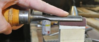
Shaped end mills can be sharpened without a special tool for sharpening cutters, along the front surface, with a thin diamond stone.
The block either lies on the edge of the table, or, if the cutter has a deep recess, it is secured as shown in the photo below. The cutter is driven along a fixed block. Sharpening end mills for wood
Sharpening end mills for wood
Before sharpening the cutter, the bearing is removed
Sharpening end mills for wood
During the sharpening process, the block is moistened with clean or soapy water. After sharpening, it is washed and dried.
As the front surface grinds down, the edge will become sharper and the diameter of the cutter will decrease slightly.
If the cutter has a guide bearing, it must first be removed (if possible) and only then sharpened. An attempt to save a minute will end in a ruined bearing and a damaged cutter. You also need to clean the cutter from any remaining wood resin using a solvent.
As when sharpening any other tool, you need to use bars of different grain sizes, depending on the thickness of the layer of material being removed and the required surface cleanliness. Before sharpening, you need to make sure that the block has the correct shape.
When sharpening each cutter, to maintain symmetry, you should try to make the same number of sharpening movements and with the same pressure.
If the material of the cutter cutters is soft enough, instead of a block, you can use abrasive paper glued to a flat surface (a hardwood strip or a strip of steel).
Wood end mills can also be sharpened on a grinding machine at low wheel speed using an appropriate abrasive wheel.
Sharpening wheels
Depending on the material from which the cutters are made, they can be sharpened with white or normal alumina wheels, CBN wheels, green silicon carbide wheels, or diamond wheels (PCD).
For example, electrocorundum wheels can provide high-quality sharpening of cutters for wood or metal made only from tool or high-speed steel of normal productivity, while CBN wheels can sharpen cutters made of high-speed steel with increased productivity, diamond wheels and wheels made of green silicon carbide - cutters made of hard alloys When using abrasive wheels (especially diamond ones), it is advisable to cool them with coolant.
One of the significant disadvantages of diamond is its relatively low temperature stability - at a temperature of about 900°C, diamond burns.
Heat resistance of various materials, °C
With increasing temperature, the microhardness of abrasive materials decreases. Increasing the temperature to 1000°C reduces the microhardness by almost 2-2.5 times compared to microhardness at room temperature. An increase in temperature to 1300°C causes a decrease in the hardness of abrasive materials by almost 4-6 times.
Using water for cooling can lead to rust on machine parts and components. To eliminate corrosion, soap and certain electrolytes (sodium carbonate, soda ash, trisodium phosphate, sodium nitrite, sodium silicate, etc.) are added to water, which form protective films. For normal grinding, soap and soda solutions are most often used, and for fine grinding, low-concentrated emulsions are used.
To increase the productivity of grinding with abrasive wheels and reduce specific wear, you should choose the largest grain size that provides the required class of surface cleanliness of the tool being sharpened.
To select the abrasive grain size, in accordance with the stage of sharpening, you can use the table in the article about sharpening stones.
The peripheral speed of the wheel when sharpening carbide teeth should be about 10-18 m/s. This means that when using a 125mm diameter wheel, the motor speed should be around 1500-2700 rpm. Sharpening of more brittle alloys is carried out at a lower speed from this range. When sharpening carbide tools, the use of harsh conditions leads to the formation of increased stresses and cracks, and sometimes to chipping of cutting edges, which increases wheel wear.
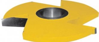
The shape of the circle for sharpening the back angle of teeth on a cylindrical surface is cup (ChTs or ChK) or disc-shaped (1T, 2T, 3T), the front angle is disc-shaped or flat.
Various shapes of grinding wheels
Mill sharpening machine
Taking into account the most difficult cases - spiral teeth, a machine for sharpening cutters must provide rotational and translational movement of the cutter being sharpened. The figure below shows a machine for sharpening end mills E-90 DAREX.
End mill sharpening machine
Orienting the cutter using a needle
The essence of sharpening an end mill is that when it moves longitudinally relative to the circle, it simultaneously rotates synchronized around its axis. Thanks to this, the sharpened edge is always in contact with the wheel at the same height (the same sharpening angle is ensured). Synchronization of translational and rotational movements is achieved using a copier needle resting on the cavity on the front surface of the tooth. By pressing the tooth to be sharpened against the needle and smoothly moving the cutter in the axial direction, the operator sharpens the tooth to its entire length in one movement.
Sharpening side teeth
. In a simplified form, sharpening screw teeth looks like this. The cutter is installed in the collet.
The tracer needle is set to a position where it is at its highest position and its tip touches the outside edge of the end mill flute.
Sharpening helical cutters
The cutter is installed in its original (extended) position, in which the needle is located near the shank, resting against the tooth groove.
The grinding wheel is moved using the side shift knob to a position where its outer edge coincides with the needle.
The engine is turned on, and the direct feed handle slowly moves the circle towards the cutter until sparking begins. After which, using the feed scale, the thickness of the metal being removed is set (usually 25-50 microns).
Sharpening helical cutters
Sharpening a tooth to its entire length is done by retracting the spindle with the cutter until the latter comes off the needle. In this case, you need to ensure that the cutter is constantly in contact with the needle. This ensures the rotation of the cutter necessary so that the edge being sharpened is in contact with the wheel at the same relative position.
Sharpening helical cutters
To ensure clean processing, the cutter pass is repeated one more time without changing the thickness of the metal being removed. This completes the processing of one tooth, and a similar operation is repeated for all other teeth. To ensure that all teeth are sharpened equally, you should not change the thickness of the metal being removed, which was initially set using the direct feed knob.
By changing the position of the needle so that its tip rests on different points on the tooth groove (on the edge or in the middle, for example), you can change the values of the angle α and α1.
Grinding of end teeth
. To sharpen the end teeth, the end mill must be set in a position in which the tooth being sharpened would be positioned strictly horizontally. The E-90 sharpening system is equipped with a graduated ring that allows you to easily and simply install the end teeth horizontally. If you are using a machine for sharpening cutters that is not equipped with a similar mechanism, you can set the horizontality of the teeth using a square.
Sharpening the end teeth of the cutter
Sharpening a tooth set horizontally is done by moving the edge of the sharpening wheel along the edge of the tooth. The sharpening angle is adjusted by moving the wheel vertically or by tilting the spindle with the cutter (if possible).
Sharpening the end teeth of the cutter
Grinding machine spindle tilt
Sharpening quality control
After sharpening, the cutter must be inspected.
The presence of chips, scratches, and cracks is checked visually with the naked eye or with a magnifying glass; with the help of instruments, the runout of teeth, angle values, and surface roughness are checked. The permissible deviations of the front and rear sharpening angles of all cutters are ±1°. Angles can be measured with a special 2URI inclinometer or a pendulum inclinometer.
Goniometer 2URI
For standard cutters, the radial runout of two adjacent (σcm) and two opposite (σpr) teeth, as well as the axial runout, is regulated. The permissible values of the radial and face runout of the cutter teeth are given in the table below (for cutters that do not have end teeth, the permissible runout of the supporting ends is indicated).
Acceptable values of cutter teeth runout
The quality of sharpening or finishing is checked by external inspection using a magnifying glass. The cutting edges of the cutters must be free of nicks and gouges.
If there are jagged marks on the surface of the tooth, the protrusions will chip away when the cutter is used, and it will become dull very quickly. You should strive to keep the surface of the tooth very smooth.
The presence of cracks on hard alloy plates is determined using a magnifying glass and wetting the plates with kerosene. In this case, if there are cracks, kerosene comes out.
Video:
When using the content of this site, you need to put active links to this site, visible to users and search robots.
Literature