Specifications
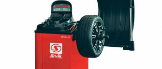
This laser engraver is equipped with a 1.8W 445nm laser module, of course, this is nothing compared to industrial laser cutters that use lasers over 50W. But this laser will be enough for us. It can cut paper and cardboard, and can engrave all kinds of wood or plywood products. I haven't tested other materials yet, but I'm sure it can engrave on many other surfaces. I’ll go ahead and say that it has a large working field measuring about 500x380 mm.
Who can make such a laser machine? Everyone, it doesn’t matter if you are an engineer, a lawyer, a teacher or a student like me! All you need is patience and a great desire to get a really high-quality machine.
It took me about three months to design and build this engraving machine, including about a month of waiting for parts. Of course, this kind of work can be done faster, but I am only 16 years old, so I could only work on weekends.
Tools you will need
For CNC milling you will need the following tools:
- Welding machine for the manufacture of metal housing. The advantage is automatic welding;
- It will be necessary to turn the studs, and perhaps some other turning work. Therefore, ideally, one would need to have access to a lathe to carry out component manufacturing work;
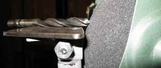
- Grinder or hacksaw for metal;
- Screwdriver;
- Hammer;
- Soldering iron;
- Scissors;
- Pliers and pliers;
- Insulating tape;
- Super glue;
- Fumlente and sealant;
- Keys for assembly.
Required materials for assembly
It's clear that you can't make a laser engraver without the right parts, so I've put together a specification sheet with almost everything you need to make one. Almost all parts are purchased from Aliexpress because it is cheap and there is free shipping on most items. Other parts such as machined rods and MDF sheets (can be made from plywood) were purchased from a local hardware store. The laser and laser driver were ordered from ebay. I tried to find the lowest prices for all parts (not including shipping).
It took a lot of time before I came up with this design. I made a few others first, but this one was truly the most beautiful of all the others. First of all, I drew all the details in a graphics editor and printed them in natural size. I assemble the entire engraver from MDF sheets 18 mm and 12 mm thick. We also chose this design because we could easily attach a Z axis and tool, turning our machine into a milling machine.
Of course, I could have made a different, simpler design... But no! I wanted something special!
Binding methods
The method of connecting the tool to the part and the machine is chosen depending on the type of processing and accuracy requirements. The principles for determining the coordinates of cutting edges are the same for all machines, but the corrector tables, commands and keyboards on the racks may differ. Therefore, we will focus only on tool movements and measurements.
Take the test
Tool binding on turning and milling machines, as well as other operations for debugging control programs, is performed in manual data input (MDI) mode. The installer must know exactly what code he is writing, since it is executed immediately after entering it.
Trimming
To determine the coordinate of the cutter along the Z axis, it is carefully adjusted to the workpiece and its end is processed. There is no need to remove a lot of material - just “whiten” the surface and align the current position of the tool with the machine zero. Before stopping the spindle, the cutter must be moved along the X axis without changing its Z position.
This method of binding to the CNC is not suitable if the end surface of the part must remain untouched.
OD turning and boring
To determine the coordinate along the X axis, the cutter is brought to the side surface of the part and machined with minimal material removal until a clean surface is obtained. It is necessary to process an area sufficient to measure the diameter. It is this size that needs to be entered into the table so that the system calculates and remembers the coordinate. In this case, the cutter is moved away from the part along the Z axis.
Determining the coordinates of a boring, threading, or any other cutter for internal machining is somewhat different. First you need to tie a drill and drill a hole in the workpiece, and then bore it. Please note that the soldering of the internal cutter “looks” in the opposite direction (i.e., it is located on the other side of the axis), so the diameter value must be entered into the tool table with a “minus” sign, otherwise the coordinate will be determined incorrectly.
The weak point of this method is the accuracy of the measuring instrument. A micrometer can be used to determine the outer diameter. Its error is 0.01 mm. To determine the diameters of the holes, it is better to use a bore gauge. It has the same measurement error. But if the bore gauge does not fit (the hole is too small), you will have to take a caliper. Even if it is an electronic instrument, it will be more difficult to achieve accuracy.
Running in with indicator
This method of tool alignment on a CNC turning and milling machine with a turret resembles the alignment of an electric motor. It is used when it is necessary to align the axis of rotation of the spindle with a drill or centering. To work, you will need a mechanical dial indicator and a tripod with a magnetic base. A calibrated cylindrical rod or the tool itself is installed in the chuck on the turret head if the smooth part of its shank protrudes from the clamping jaws.
A tripod with an indicator is attached to the spindle so that the measuring tip rests on the cylindrical surface of the shank. The spindle is turned by hand and the indicator readings are looked at. By moving the turret along X and Y, a position is achieved in which the arrow will remain motionless in any position of the spindle, and this is taken as zero.
Feeler gauges or gauge blocks
If the surface of the workpiece cannot be machined, measuring blocks or feeler gauges with known dimensions can be used to determine the Z and X coordinates. The cutter is brought to the part with a gap: so that the end measure does not pass through. At minimum feed, retract the cutter until it enters. The thickness of the tile must be added to the correctors.
Please note that when determining the coordinate of the cutter along the X axis, the thickness of the measuring tile is multiplied by two and added to the diameter.
Paper
This method is suitable when there are no high precision requirements for processing: cutting sheet materials, processing facades. Instead of a gauge block, paper is used, and the cutter is brought closer to the workpiece until the sheet is clamped between them.
Electronic sensors
Many machines are equipped with electronic tool setting sensors, also called tool setters. Working with them is convenient and fast; coordinates are determined automatically, which eliminates the possibility of error. The tool setter is called by a command from the rack. The tool is brought manually to a distance of about 3 mm from the sensor, after which a command is given to determine the coordinate. In automatic mode, the cutter touches the surface, and the machine system itself makes the calculation and makes a correction in the tool table.
There are also sensors and complete measuring systems that can be purchased separately. One of the most well-known manufacturers of such equipment is Renishaw. The company manufactures contact sensors for attaching tools, parts, and carrying out high-precision technical measurements.
Build process
After printing out the drawings, I had parts that needed to be put together. The first thing I did was install the electronics housing door on the left side and the hinge lock (the door installed without difficulty, so I did that first. To assemble the electronics housing, I used a lot of L-shaped iron brackets with holes for self-tapping screws If the body is planned to be made of plywood, then you must first drill holes in it for self-tapping screws.
Instructions for assembling a homemade CNC milling machine
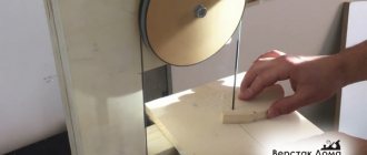
Below in the photo you can see a self-made CNC milling machine, which comes with detailed manufacturing and assembly instructions indicating the materials and components used, exact “patterns” of the machine parts and approximate costs. The only negative is the instructions are in English, but it is quite possible to understand the detailed drawings without knowing the language.
Download free instructions for making the machine: Homemade CNC milling machine
The CNC milling machine is assembled and ready to go. Below are some illustrations from the assembly instructions for this machine.
conclusions
This is, perhaps, all the information that he conveyed to us, but this is a pretty good instruction for those who have a dream of assembling with their own hands a good homemade laser machine for home and hobby purposes.
The assembly of the laser engraver itself is not particularly expensive, since the number of parts is minimal, and their cost is not particularly high. The most expensive parts are probably stepper motors, guides and, of course, parts of the laser head itself with a cooling system.
This particular machine deserves special attention, since not every laser engraver allows you to quickly install a milling machine on the 3rd axis and turn the machine into a full-fledged CNC milling machine.
In conclusion, I would like to say: if you really want to assemble a high-quality CNC machine with your own hands, which will serve faithfully for many years, you do not need to save on every detail and try to make the guides smoother than the factory ones or replace the ball screw with a stud and nut. Although such a machine will work, the quality of its work and the constant adjustment of mechanics and software will simply frustrate you, making you regret the time and money spent on it.
When is binding necessary?
On any CNC machine, tool binding is done before setting the part zero. Tool overhangs are determined in the following cases:
- If you have a multi-spindle machine or a turret, you need to make an assignment for each tool before starting machining. The machine system will remember all values.
- If you have a simple machine with one spindle, you need to tie it every time after changing a cutter or cutter.
- After sharpening the tool. To set a reduction in the length of the drill or a change in the size of the cutter tip, you can use wear correctors, which are available in most systems. However, if you are just starting to master the machine, it is better to determine the tool overhang every time after sharpening, so as not to make a mistake.
After replacing the carbide insert on the cutters, binding to the CNC of the machine is most often not required. It is enough to make a control measurement of the surface treated with it.
Connecting an inductive sensor to the controller
You have normally open sensors, so you need to connect the inductive sensor to different inputs on the board. Because there are few inputs on the board, so connect only basic ones to different pins. But remember that they will be the end ones along these axes (x+ y+ z+). Connect the limit switches along x—,z—,y— in series and connect to one pin.
On each inductive sensor, place a resistance of 1k-2.7k, between the black and blue wires. Connect the negative ends of the axes in series, as in the diagram below.
inductive sensor connection diagram
brown plus (+), blue GND, black signal
For example configuration option:
X Home 11, also known as x+ limit switch. black wire
Z Home 12, also known as the limit switch for z+. black wire
Y Home 13, also known as limit switch for y+. black wire
x—,z—,y— to pin 15, the connection of the three sensors is serial. As in the diagram above.
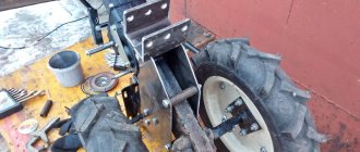
Stepper motors
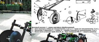
The design of any CNC-equipped milling machine necessarily contains stepper motors that ensure the movement of the tool in three planes: 3D. When designing a homemade machine for this purpose, you can use electric motors installed in a dot matrix printer. Most older models of dot matrix printing devices were equipped with electric motors with fairly high power. In addition to stepper motors, it is worth taking strong steel rods from an old printer, which can also be used in the design of your homemade machine.
Attaching the stepper motor to the upper carriage
To make your own CNC milling machine, you will need three stepper motors. Since there are only two of them in the dot matrix printer, it will be necessary to find and disassemble another old printing device.
It will be a big plus if the motors you find have five control wires: this will significantly increase the functionality of your future mini-machine. It is also important to find out the following parameters of the stepper motors you have found: how many degrees are rotated in one step, what is the supply voltage, as well as the value of the winding resistance.
To connect each stepper motor you will need a separate controller
The drive design of a homemade CNC milling machine is assembled from a nut and a stud, the dimensions of which should be pre-selected according to the drawing of your equipment. To fix the motor shaft and connect it to the stud, it is convenient to use a thick rubber winding from an electric cable. Parts of your CNC machine, such as clamps, can be made in the form of a nylon sleeve into which a screw is inserted. In order to make such simple structural elements, you will need a regular file and a drill.
Options for homemade guides
The guide mechanism for CNC is often based on the use of a chrome-plated metal pipe.
The guide mechanism can be made from a chrome-plated metal pipe
It has a low cost and is easy to process by changing its shape. In addition, there are a number of disadvantages:
- The protective top layer wears off very quickly, then the metal wears out faster.
- When the load on the pipe is high, it does not provide the necessary strength.
This solution is cheap for a specialist, but such a machine will only last for a few tens of hours. This is due to the disadvantages of galvanized or chrome-plated pipes, which themselves are made of soft metal, subject to rapid wear under load. A router used in conjunction with such guides will significantly reduce their service life.
In addition to these methods, milling cutters with low power should be used as moving parts of the device. They give the manufactured parts precise, thorough processing; they are most often used on woodworking machines. They have a low price and short production time.
Shaft and its types
It is worth giving a brief description of the other types.
- The spline shaft is characterized by the presence of a special track for the bushing balls. Characterized by greater rigidity and wear resistance, compared to a conventional shaft, it is suitable for mechanisms in which it is desirable to install guides at the ends. They are used extremely rarely in the design of machine tools due to their high cost.
- The shaft on a support in the form of cylindrical rails of a linear type does not allow sagging under load and its own weight. It is mounted on the frame, securely fixing it. Despite the disadvantages, expressed in the presence of large play in the bushings and their short service life, cylindrical rails have a large load capacity. Different from linear bearings, the carriage reacts differently to the degree of load. A small CNC machine that has a heavy spindle has the potential for reduced accuracy.
- The purpose of profile rail guides is greater accuracy. They are also attached to the frame. Thanks to special raceways, the loads on the carriage are distributed evenly over the surface, and the contact profile of the ball to the rail is an arc. Among the advantages are the presence of good load capacity and wear resistance, and backlash is minimized. The difficulties of producing such rails have a negative impact on pricing; they are expensive. This especially applies to guides supplied by well-known brands whose machines are numerically controlled.
- Roller rails have flat raceways, and in the support module, in place of the balls, rollers are installed that improve all the parameters of the guide. They are used in machines that mill ferrous metals, steel and stone.
- Dovetail is chosen for industrial metalworking equipment if increased fastening rigidity is required. In guides of this type, flat surfaces slide with a maximum contact area. They are made in the form of a monolith with a frame. Due to the complexity and labor-intensive manufacturing and repair process, these guides are therefore not accepted by the hobby machine tool industry.
CNC development
Each individual machine has control commands, they are written in the instructions. Using this set, you need to code the entire layout for the desired available options. These may include the following:
- Startup and shutdown.
- Selection of cutting tool.
- Moving a cutter along two or more planes.
- Determination of cutting mode and speed.
- Additional mechanisms, such as chip removal or lubricant supply.
The introduction of this program can be carried out in two ways:
- On a personal computer, using specialized software, encoding occurs automatically, then the ready-made set of commands in the code is transferred to the equipment using a recording device.
- On the machine itself there is a stand from the numerical control panel. There you can enter the necessary commands.
Factors to Consider
It should be remembered that the more complex the device, the more nuances of use. Important things to consider:
- How many tools can be used simultaneously - the number of tasks performed in parallel.
- What operating power is used.
- Feed speed. If you select a parameter higher than recommended, this can lead to overheating of the workpiece and cutting edge, leading to defects and deformations.
What types of guides are there?
Any machine is based on the precision of processing, which is provided by guide rods. You have to make working units with your own hands, but there are some that you can’t make yourself; only factory-made parts are suitable.
For example, it is unlikely that it will be possible to manufacture the working part of a milling machine, just like with a drilling or turning machine. Therefore, you have to use ready-made solutions - drills, drives, engravers or electric jigsaws. With guides, the situation is simpler, since their characteristics and appearance directly depend on the purpose of the unit.
Almost all of them, used in factory and home-made structures, are of only two types - sliding and rolling. According to the principle of bearings, their method of operation is clear - some are based on sliding, others use rolling bearings in their design.
For low-power equipment that does not require precision and performance, the sliding principle is used. Basically, such parts are used by desktop drilling and turning units, as well as woodworking units. There are also subspecies, but let’s look at those that are easiest to make with your own hands from what is on sale.
Principle of operation
Before you start assembling such a unit at home, it is important to understand how it works. There are three main conditions that allow a laser to work properly. If at least one of them is not met, a beam of the required intensity simply will not arise. These are the conditions:
- Power supply.
- Working environment.
- Optical resonator.
The energy source fills the working environment with photons of a certain charge.
These photons are taken from the active medium by particles that are similar to them. When moving in a liquid, photons begin to accelerate due to collisions with atoms of the working medium, this leads to an increase in the potential of the installation.
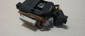
At the other end of the tube, frosted glass is installed, through which the photon beam exits. The beam is formed in such a way that all its photons meet at one small point, superimposing their energy on each other, as a result the processed material is burned.
Video: DIY CNC laser machine.
Connecting CNC limit switches
Well, I’ve come to the main thing that requires explanation. The left block is used for input signals. As you can see, the CNC limit switches and the base switches are connected to different terminals. But they all have a serial connection. A special feature is the parallel connection of the basic switches along the Y axis. On the Zhelezkin channel I posted a video Connecting CNC limit switches
Since I use two Nema 17 motors on the Y axis, synchronization may be disrupted. For this purpose I installed two CNC limit switches. One end on the left side. The second end is on the right side. When you press the Home button, the Y axis will only stop when both switches are open. If there is a synchronization violation, then the left and right ball screws will not immediately return the Y axis to its initial position. First one of the sides will approach, and then the other. So, until the lagging side reaches its position, there will be no pressure on the end one. And the movement will continue until the CNC limit switches are pressed. This eliminates synchronization problems.
The CNC limit switches are connected to pin P 13 of the board. Like the base ones, they are connected in series. But I also connected a button to pin P 13, which I called “rollback”. What is it for? Because when the machine is operating, it is possible to go beyond the boundaries of the working field. Since in such cases it will be impossible to bring the axis into the working position due to the pressed limit switch. Therefore, you will have to first release the end from pressing. This can be done in different ways. But all this takes a long time and is not very convenient. That's why I put this button.
Conclusion.
I connected the button in parallel with the end ones. When the axis goes beyond the limits, just press the button and, without releasing it, bring the axis into the working position. In other words, when pressed, the button bypasses the operation of the terminals. The rest, I think, requires no explanation. In the program settings, I configured the end and base in this way. When you press the accept base button, the end ones connected to P 11 work as base ones. But when executing the program, these same CNC limit switches will perform the function of emergency limit switches. You can read about setting up the program in my article, and also on Zhelezkin’s YouTube channel there is a video diagram of a CNC machine. And also a lot on CNC and other homemade products.
Reply to Evgeniy's comment.