Vector slipway
Having worked as a tinsmith for over 12 years, I can share my experience in the hard work called “body repair”. I have worked on various slipways, almost all existing types. I also made stocks of my own designs, which is what I do now, only at a higher level. And now I would like to bring to your attention a brief overview of straightening stands for body repair.
Modern body equipment manufacturers divide their products into several types.
- Rolling slipways.
- Platform slipways.
- Floor slips.
- Frame slipways.
Let's consider the advantages and disadvantages of all designs.
Almost everyone who has purchased straightening devices (aka rolling stocks) is very surprised when they start to pull. The thing is that the maximum load zone in such a structure is not attached to anything, while the twisting force of the hydraulics of 10 tons, just like on other structures, tends to turn the power device upward.
When purchasing and then installing a car on a rolling slipway, its flaw is not so noticeable, but as soon as you start applying pressure to the hydraulics, the tower rushes up! By the way, there will be no effort on the pump handle.
View from above. The presence of sliding hind legs has practically no effect on this position because the maximum load zone is located on a transverse spacer with clamps, which, with a little effort, easily rotates around its axis.
You can only work on these devices by creating additional support on the car body.
But in any case, do not count on being able to repair severe damage using such devices. Honest manufacturers speak about this directly (AUTOROBOT MICRO). And some Chinese products costing about 40 thousand are not functional at all.
The most popular type of slipway now, among owners of large and developing car services, is also burdened with disadvantages.
Installing\removing the machine:
- The platform tilts on one side and the machine is pulled onto it by a winch.
- The entire platform lowers and the car drives onto it by itself.
- Scissor lift platform
Each of the presented options assumes the serviceability of the suspension or existing installation rolling system . To repair a car in the second and third examples of a platform slipway, you will also need a working engine, a winch or a support team.
Power devices:
The key advantage of modern platforms is towers. They roll on rollers around the entire perimeter, are fixed anywhere by turning a lever or a pin, and have a constant 10-ton force at any height. It’s true that it’s not clear who needs such effort when fixing a roof.
Flaws:
- The dimensions of the platform slipway minimally require a room measuring 4x7 meters.
- There is no way to repair the suspension.
- There is no possibility to work under the machine.
- Platform height 500-800mm (For those who are just going to buy themselves a platform slipway: During repairs, you will have to stand cancerously and reach for the machine located at a distance of half a meter, and also periodically step to the height of the table. Enjoy your use.)
- The width of the working area on the platform itself is 300-500mm.
- The platform slipway is not used by any OD in Russia.
- The minimum price of a platform slipway is 300,000 rubles.
A very good option for those who have their own premises and a scissor lift that retracts into the floor. Excellent access to any point of the car, comfortable height. If there is no work - a flat area. The floor slipway, like the platform one, has several varieties. I'll give two examples.
- Filled floor structure (rails)
- Anchor floor structure
Installing\removing the machine:
Nothing complicated. The car drives onto the repair site and is lifted with a jack. The most convenient height when working on this type of slipway is from 600mm. In this position of the car, there is no need to go around the exhaust area in single file. Of course, lifting the car to such a height is problematic, but this design miscalculation is easily corrected by a scissor lift.
Power devices:
As a rule, they are tower type, equipped with wheels. The slipway tower moves on wheels and is disconnected in two or three places to change the thrust vector. The key difference between a floor-mounted tower and a platform one is the absence of rollers.
Flaws:
Rails.
- The dimensions of the floor slipway minimally require a room measuring 5x8 meters.
- Having your own premises.
- Construction works.
- Inconveniences when moving the tower.
- Inconveniences when installing the machine without a scissor lift.
Anchor.
- The dimensions of a floor slipway with anchor fastening require a minimum room size of 5x8 meters.
- When installing the slipway, without worrying too much, we drill 100 holes for the anchors.
- Lack of level ground, with the exception of complete dismantling of the slipway upon completion of repairs.
- Inconveniences when moving the tower.
- Inconveniences when installing the machine without a scissor lift.
First option.
The power device (S.U.) is attached to the frame at one point and operates using the strength of the frame in this place. The frame is 3.5-5m long, and S.U. 0.7-1.3m. It is not advisable to make it longer because... the twisting load increases. A long frame is needed in order to reduce the length of the S.U. and attach it to one point on the frame. This entails an increase in the thickness of the pipes from which the frame is made and, as a consequence, the mass of the slipway. However, this makes it possible to install the slipway on a lift. A classic example of this is the MARK 6 slipway from CAR-O-LINER. I worked on such a slipway for some time and I will say that the thing is quite convenient. Especially if there is a lift. During repairs, rearrange the three-joint S.U. rarely required on the frame.
If you have a lift, you can also do metalwork, reinforcement, and painting work. A frame slipway with a lift can be lowered into a pit on the floor and a flat platform is obtained. Today, stocks with a lift are produced and have a folded height of 100-120mm, i.e. Almost any car can pass over it, this seriously saves the time of installing and removing the car, and also allows you to use the slipway as a simple lift, with a lifting height of 800-1200mm. Several European, American and, of course, Chinese companies produce similar slipways - these models are the most convenient of all slipways today, and with a limited service area, this is generally a godsend. Having such a tool, you can do any work with the machine practically in one place:
- Suspension repair
- Change of oil
- Tire service
- Fittings
- Preparing for painting
Those who have worked in a body shop will understand what I'm talking about. How much more convenient it is to work if the machine can be lifted on a special lift. At modern stations, scissor lifts are required in painting shops.
The only thing holding back the mass use of these slipways is their price. Even weak Chinese products start at 250 thousand rubles, not to mention European CAR-O-LINER SPEED from 650 thousand rubles.
For more than a year I developed, made models, tested individual elements, selected components and finally gave birth to Vector NZ! A slipway belonging to the described type, but equipped with a scissor lift with a lifting height of 1 m. The NZ has a very strong frame. During testing I worked with 20 ton hydraulics. The lift lifted a long loaded Ford Transit (2.8 tons) see photo on
.
Second option.
The power device is attached to the frame at two points spaced apart from each other. With this scheme, the twisting load is distributed more rationally and the slipway can be made lighter. The frame of the slipway has a length of 1.5-2.5 m, S.U. also 2-2.5m. Since all the power elements of the car body are located at its edges, it is advisable to place the basic attachment points of the S.U. not in the center of the frame, but on the side. S.U. placed opposite the spar can develop more force.
On the Vector S , the frame and power device are made in the same way. But in addition to evenly distributing the load across the frame, S.U. retains the ability to be secured anywhere and at any angle. Also, on the basis of S, a whole family of slipways was created, distinguished by a long frame, S.U. (two and three hinged), clamps for flanging, etc.
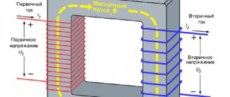
Now about power devices. First, a little theory.
Each car has a power frame that suffers during an accident and the straightening of which is the main task of body repair on the slipway. The closer the damage is to the safety capsule, the more difficult the repair will be and the greater the effort required on the slipway. Let's see how the loads will be distributed during a frontal impact and how different designs of slipways will perceive these loads.
When the spar is pulled forward, two main forces act on the frame and the power device (S.U.) attached to it. F1 – Tends to bend the frame backwards, and force F2 – will twist it upwards. And the greater the distance A, the greater F2.
Front view. If you pull the spar with the slope of the chain, then another force appears that tends to pull the arm to the side. In order to avoid this, the hand must be tilted to the side in advance. Or rearrange the s.u. entirely opposite the spar.
If we imagine that the vertical and horizontal parts of the system. form a plane, then the chain when stretched should be in this plane. If this does not happen, then under load a force appears that forces the arm to the side.
Tower.
They are used mainly on platform and floor stocks. The use of these devices on frame stocks is extremely rare. Tower s.u. distinguished by the largest mass . But the main difference is that despite the height and direction of the thrust vector, the force will be constant.
Lever.
The most common. They are used on almost all frame and rolling stocks, and are limited to floor ones. They are distinguished by their simplicity of design and low weight . The higher the chain is mounted on the lever, the less force it develops.
Vector.
The simplest in design, but at the same time, allowing not only to pull, but also to push, raise and lower body elements. True, they are the most difficult to use.
Almost all manufacturers of slipways produce clamps equipped with replaceable jaws with a special notch. Clamps vary in width from 80 to 250mm . Narrow clamps are not the best option if the repair takes longer. From hanging on the slipway for a long time, the machine can “rely” on narrow clamps ( the threshold is deformed ). There are no such problems with wide clamps. Some manufacturers, instead of jaws, use steel pins (cut dowels), which, by piercing the metal flanging, very securely fix the car, but after removal from the slipway, 48 holes . We treat one thing and cripple another. Whatever body clamps you use, with high pulling forces it is recommended to use a chain attached to the frame of the slipway and the power point of the body opposite the traction clamp. For example, when pulling the spar by the subframe bolt.
that no matter what kind of slipway you choose, remember one thing: THE STYLE IS A TOOL. How you use it depends not only on its successful operation, but also on your earnings (you can also hammer nails with a microscope). I wish you successful work and the right choice of equipment!
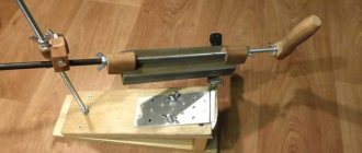
Mobile homemade slipway
This is the kind of slipway our forum member Evsey made.
The design of the lightweight and mobile Finnish slipway Autorobot micro A was taken as the basis.
The main materials used in the manufacture of steel were channel No. 10 and No. 12.
Below in the photo are the main components of the slipway.
- Swivel lock
Swivel lock
- Cross member
Cross member
- Cross member
Cross member
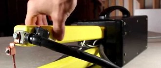
- Power tower
Power tower
View the embedded image gallery online at:
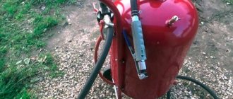
An important detail of the slipway is the sill grips, a kind of vise. For their manufacture, sheet steel 16 mm thick was used. The width of the sill grips is 150 mm, the tightening bolts are 12, and the bushings are 14 mm. The springs were used from the valves of the classic VAZ. The “jaws” of the grips are made of metal rasp.
To work with this slipway, hydraulics from the kit are used, designed for 10 tons. This is the chain clamp located on the draft tower (boom) of the slipway, and also how the sill grips work.
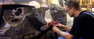
Slipway in operation:
- Slipway at work
Slipway at work
- Slipway at work
Slipway at work
- Slipway at work
Slipway at work
- Slipway at work
Slipway at work
View the embedded image gallery online at:
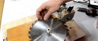
And here is the actual diagram with the dimensions of the slipway.
To simplify the work, special stands were welded with the car driving onto them from the front or back, and it became easier and also much faster to bring the slipway under the belly of the car.
- Bridges
Bridges
- Slipway at work
Slipway at work
- Slipway at work
Slipway at work
- Slipway at work
Slipway at work
View the embedded image gallery online at:
This design of the slipway has the ability to install a device to pull down. To do this, you need to modernize it a little by placing a sliding roller under the chain links.
Pros and cons of this do-it-yourself slipway design. It may be worth taking them into account if you repeat this or a similar design.
Cons and improvements:
- There are only two sill grips and no height adjustment.
- Lock for turning the boom horizontally: there was 5 mm iron, a minimum of 10-15 mm was needed.
- During operation, weak points began to emerge and were strengthened.
- The length of the telescopic boom is, in principle, excessive, so it can be made shorter.
- How to hook a car to the sills from below with these grips if they do not have flanges, for example, a BMW type car? To do this, you will need special adapters, which cost quite a bit of money (there are homemade options).
Pros:
The mobility of the slipway and the ability to turn it in different directions can be considered both a plus and a minus, but in a small garage there will be a problem with movements. On the other hand, not every car repair requires the use of a slipway, and in this case it can simply be rolled out of the garage. And for a small garage it will be more practical to make a stationary slipway (we’ll talk about it a little later).
General impressions of Evsey (the author of the project) from working with his slipway:
In general, it’s beautiful, the car stands dead on the slipway, the hydraulics pull extremely easily, as if you weren’t pulling iron, but cardboard or paper. Before this I used a regular winch, so I can compare and say that this is heaven and earth. Stapel has proven himself to be a real hard worker, his rating is 5 plus, he is very mobile and reliable.
You can read details and discussion of this design on our forum here.
As one of the options for a small homemade slipway for use in the garage, below is the video from Boris AvtoDok, where he talks in detail about his design.
In the second video, errors identified during work, how he corrected them and what modifications he made.