Almost every home craftsman can independently assemble such a useful device as a spotter. To solve this problem it is not at all necessary to have a serious understanding of electronics and to have the relevant experience. And the components that are necessary for the manufacture of such a device are not difficult to find: to do this, just dig around in your workshop, in the garage, look in the market or from friends.
Factory spotter. Our task is to make an inexpensive analogue with your own hands
Scheme for assembling a homemade spotter
If you are going to make a spotter with your own hands, you need to understand the circuit diagram of such a device.
The most important element of the spotter is the welding transformer (T2), voltage is supplied to its primary winding passing through a diode bridge. In the electrical circuit of the second diagonal of such a bridge there is a thyristor, which is controlled by the voltage coming from another transformer (T1), which has a low power.
Schematic diagram of a spotter
This scheme works according to the following principle: when the spotter is turned on, voltage is supplied to transformer T1. It is converted and supplied from its secondary winding to the diode bridge, then passes through the closed contacts of the “Impulse” switch to capacitor C1, which begins to charge. Since the thyristor is closed at this time, no electric current is supplied to the welding transformer.
To start this transformer and receive welding current on its secondary winding, it is necessary to change the position of the “Impulse” switch, which will disconnect capacitor C1 from charging and connect it to the thyristor control circuit. The current generated as a result of the discharge of the capacitor first passes through the resistance (R1), which is responsible for the operating modes of the device, and enters the control electrode of the thyristor, which leads to its opening.
After the thyristor opens, a short-term pulse is sent to the primary winding of the welding transformer, the characteristics of which (duration and current) depend on the parameters of capacitor C1 and resistance R1, as well as on their ratio. As a result, the secondary winding of the transformer will produce a powerful pulse current, the strength of which can be in the range of 300–500 A, the duration of such a pulse is 0.1 seconds.
This duration can be adjusted, for which variable resistance R1 is responsible. After capacitor C1 is completely discharged, the control thyristor will close and the electrical circuit of the device will return to its original state. In order for capacitor C1 to begin charging again, it is necessary to change the position of the “Impulse” switch.
Spotter control diagram (click to enlarge)
A homemade spotter is made with the following components at its disposal:
- a transformer that will create the welding current;
- a transformer that will provide power to all elements of the electrical circuit of the device;
- an assembly of diodes designed for a voltage of at least 12V;
- diode bridge (V5–V8);
- thyristor (PTL-50);
- a variable resistor with a nominal value of 100 ohms.
A ready-made transformer that provides the formation of welding current is quite difficult to find. It is much easier to assemble such a device with your own hands. The magnetic core, which is the basis of such a transformer, must have a working cross-section of at least 400 mm2, and its dimensions are calculated taking into account the placement of the windings.
Types of design of magnetic cores of transformers and their dimensions for calculating the cross-sectional area
The working cross-section of the magnetic core of the transformer that you are going to install on your spotter, as well as the dimensions of its windows, are selected independently. For an W-shaped core, the primary winding of the transformer, consisting of 200 turns, is made of wire with a cross-section of 2.5 mm2. The secondary winding has 7 turns, for which a wire with a cross-section of 50 mm2 or a bus of the appropriate cross-section with insulation is used.
To protect your spotter from sudden failure, and yourself from electrical injuries, the primary and secondary windings of the transformer must be insulated from each other. For this purpose, you can use cardboard, varnished cloth or several layers of paraffin-impregnated paper. The length of the outgoing ends of the secondary winding of the transformer must provide for the possibility of its connection to the output terminals, and the primary - for connection to the electrical circuit of the device. It is advisable to impregnate the transformer you have made with shellac.
Transformer with a ring core: primary - 255 turns of wire with a cross-section of 1.8 mm, secondary - 7 turns of copper bus 6.5x4 in three layers (75 mm2)
The electrical circuit of the spotter contains a supply transformer, the voltage on the secondary winding of which is 12 V. You can select any transformer that satisfies the above parameter. To control the presence of voltage on such a device, equip it with an additional winding.
If difficulties arise with the search for a TPL-50 type thyristor, then you can select any other that meets the following parameters: reverse voltage value - at least 220 V, forward pulse current - at least 50 A. To assemble the diode bridge with which the spotter is equipped, you can use any diodes that meet the following characteristics: reverse voltage - at least 220 V, forward current - at least 50 A.
To construct a spotter with your own hands, you will need to find a variable resistor with a nominal value of 100 ohms. Such a resistor can have any power dissipation. The capacitor that will accumulate the electrical discharge must be electrolytic, with a capacity of 1000 μF and a voltage of 25 V.
Spotter option with two transformers
Spot welding controller
Version 3.1
Version for XX currents not exceeding 2 A!! (version 3.2 is more reliable and works with currents xx from 0 to 20A, tested)
Version on (twisted) variable resistors - delay time, power, pulse time are adjusted. The button switches auto or manual mode.
Description files, etc. in the attachment.
Atmega 8 only in TQFP package..... it won’t work in the DIP since the dip does not have ADC6 and ADC7 inputs
SPOTTER 3.1.rar 272.1K 1899 downloads
Version 3.2
Improved version 3.1, Can measure pulse voltage, the circuit and wiring also provides for measuring pulse current but is not programmed yet. (you don’t have to make a voltage measurement circuit) Software setting of autostart. Attached is a photo of the finished controller. The video shows how the controller works and how to set up autostart. The meter on the Attini 85 mk can be replaced with Attini 25, 45.
SPOTTER_3.2.rar 602.07K 2840 downloads
Version 2.5
For version 2.5.1 —- On the display — Q=…. – power (cut-off angle is adjustable…. 10 – 100%) t1=…. – delay time (adjustable from 0 to 5 sec in steps of 0.1 sec) t2=…. – welding pulse time (adjustable from 0.1 to 5 sec.) t3=…. – time between pulses (0.1-5 sec) N=…. – number of pulses (from 1 to 5) Temperature of the triac (in the menu, the temperature for turning on the fan and the temperature for turning off in case of overheating of the triac are entered in advance) To exit to the settings menu, you need to press and hold the “>>” button (in the diagram), the temperature is adjusted in the menu turning on the cooling fan, temperature of thermal protection (shutdown), recovery time (readiness for the next process after the end of the previous one and turning on and off the sound. An autostart setting has also been added - manual and automatic. When power is applied, a poll is made to close the secondary power trans - if the secondary if the controller is closed, it will be locked - to unlock it, you need to open the secondary accordingly, but if this cannot be done for specific reasons, then you need to press and hold the “START” button until the signal .... then the controller goes into normal operation mode.
Wiring of the control unit for SMD, power unit for DIP.
The power unit uses a converted electronic transformer as a power source. A DC-DC Step_Down module with adjustable output voltage is used to backlight the display.
There can be any food options.
Two hex files are attached - for the Russian version and the English version.
SPOTTER 2.5.1.rar 652.68K 1932 downloads
Hidden text Firmware update (04/24/2016) version 2.5 to version 2.5.1 (scheme without changes) Automatic and manual autostart settings have been added to the menu.
SPOTTER_2.5.1.rar 9.82K 1211 downloads
Hidden text (((Updated 05/12/2016))) New firmware version (version 2.5.2) - the MCP131T-450 supervisor can be excluded from the scheme. If the recording of settings is not saved when the power is turned off, then it is necessary to increase the capacitance of the VCC power supply capacitor to 1000 - 2000 microns. …. The blinking “Start” LED when the power is turned off indicates that the recording has been completed.
SPOTTER_2.5.2.rar 93.71K 1698 downloads
Testing program for checking sync pulses and at the same time beepers and LEDs. Version 2.5 (test).rar 2.62K 1044 downloads Field key IRLML0060 or any other for the appropriate current (cooler), bipolar can be used.
Attached images
Post edited by alek956: 02 December 2021 12:55
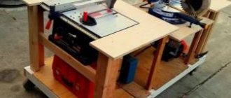
Homemade spotter body and other components
Even if you make a spotter with your own hands, you need to take care of the body for it. First of all, you need to make a base for your equipment, for which you can use a plate of dielectric material. It is important to make the dimensions of the finished base such that all the components of the spotter can be placed on it, and convenient access to the places where installation will be carried out is provided. To do this, you can first prepare a drawing, drawing to scale all the structural elements of the device.
To protect all the internal elements of your homemade spotter and give it an aesthetic appearance, it is convenient to use a casing from an old microwave oven or welding machine. If you plan to frequently carry your spotter, then you need to evenly distribute the weight of its internal components and provide reliable fastenings for a belt or portable handle. In addition, small wheels can be mounted on the lower part of the base of the device, which will also make the device more mobile.
Option for the body of a homemade spotter
After you make a spotter with your own hands, you need to equip it with additional components, which include:
- a pistol, which is the working part of the apparatus;
- two welding cables;
- inopuller, which is also called a reverse hammer.
When choosing welding cables, it is very important to choose the correct cross-section. To do this, you can make a simple calculation: for 10 A of the maximum permissible current that the spotter produces, there should be 1 mm2 of cable cross-section. For the mass, you should use a cable whose length does not exceed 1.5 m, for the worker - no more than 2.5 m. If you neglect these requirements and use longer cables, this will lead to significant losses in the welding current, which will negatively affect the quality performing welding work.
The connecting elements must be securely fastened at the ends of the cables. These can be terminals for threaded connections or devices that provide quick connection with the corresponding terminals on the device itself and its working part - the gun. On the reverse side of the cable for ground, you can install a quick-clamping element (crocodile) or equip it with a terminal for threaded fastening.
Working spotter pistol
As mentioned above, the main working part of the spotter is the pistol. If you plan to constantly use a homemade spotter in your work, then it is better to purchase a factory pistol. If you need such a device for occasional use, then you can assemble a working element for it from improvised means.
Spotter gun assembly with return hammer
As such improvised means, they usually use an assembly glue gun or the working part of a semi-automatic welding machine. You can make a comfortable and reliable handle for a homemade pistol from getinax or textolite with a thickness of 12–14 mm, cutting out two identical rectangular parts from them. In one of these parts a recess is made in which the bracket necessary for attaching the electrode is placed. Here you can also place a light bulb, a button to turn on the backlight and a switch responsible for sending an impulse.
You should take a very responsible approach to the manufacture of the bracket in which the welding electrode will be mounted. This bracket is made from a copper pipe of square or rectangular cross-section. The electrode itself is made of a solid copper rod, the diameter of which should be 8–10 mm. It is very convenient if the design of your homemade gun is such that you can replace the electrode in it without disassembling it.
To connect the gun to the spotter itself, you must use a welding and control cable, which should have 5 cores with a cross section of 0.75–1 mm2 each. Three wires of the control cable are connected to the “Impulse” switch, two - to the light bulb responsible for the backlight and its switch. The end of the welding cable is carefully stripped and sealed into the hole in the bracket.
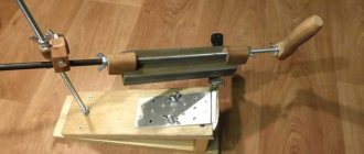
Inopuller (reverse hammer) for a homemade spotter
If you figure out how to make a spotter, then making a reverse hammer for it with your own hands will not be a big problem for you. Don’t be afraid to waste time working on such a device, because factory models of inopullers are quite expensive.
As a basis for the manufacture of such a device, you can take a mounting gun. The part into which the container with mounting foam or sealant is inserted is cut off. Three rods with a diameter of 6–10 mm must be welded onto the cover that is now freed, which will act as racks. A ring made of a rod with the same cross-section is welded onto the free ends of the posts. The diameter of the ring, which after installation must be wrapped with several layers of insulating tape, which will prevent it from being welded to the leveled surface, should be approximately 100 mm.
It is also necessary to cut off the curved part of the mounting gun rod and the stop. Instead of the cut stop, a fastener is welded to which the cable coming from the stopper will be connected. For such fastening, you can use an M10 threaded bolt and two nuts. The cut part of the rod must be sharpened, giving it a conical shape with a diameter of the end part of 3 mm. To make such a simple device, you will need about an hour (or less if you first watch the video of this process).
When working on a spotter (especially a homemade one), safety precautions should be observed. If you straighten car body parts using such a device, do not forget to disconnect the battery terminals.
Inopuller for a spotter from a mounting gun
In addition to the spotter itself, you will need special washers for the job. They are welded using this device to the straightened surface using spot welding technology. You can also make such washers and other devices for work with your own hands.
Materials
A spotter from a welding machine will require materials and tools to create the installation. Sheet iron 35-40 cm2 is required, since it will not be possible to make a spotter without it due to the risk of overheating. The temperature on homemade equipment increases only in places after the cable; additionally strong heating occurs on the iron rod with a diameter of 16 mm. To reduce the temperature at the stem, it is preferable to use brass.
The welding transformer for spotter, designed for spot work, is somewhat different from the classic design
The characteristics of the power cable are determined depending on the power of the spotter, but it is preferable to choose 70 mm2 or more. It is better to take a wire for ground 1.7 m long, and for connecting a hammer - 2.1 m. It is advisable to equip a spotter with your own hands from a battery with control using pulses through a thyristor ТЧ-40.
Initially, the outer winding of the transformer is applied using a copper busbar with dimensions 6, 5, 4 on the 3rd layer of the winding. When using a battery, it is permissible to replace the wire with an aluminum one. An additional two are applied to the second winding. At the end of the work, the battery-based equipment should be made of aluminum or copper with an area of 250 mm2 (5 windings of 6 turns each).
It is important to pay attention not only to the functionality of the installation, but also to ease of use. The design of the inertial hammer creates conditions for safe and easy use of the device. The glue gun spare part is mainly used.
A layer of thermal insulation and a wire for switching must be applied to the power cable. Thermal insulation should be applied with reserve, since when heated it shrinks and the area may be exposed.
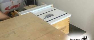
Making a spotter from a welding machine
The above-described scheme for making a spotter is convenient to use if you have a serial or home-made welding transformer. In this case, you will only need to select diodes and a thyristor with the required parameters to retrofit it.
The network describes a lot of options for making a spotter using other schemes. Home craftsmen demonstrate both quite functional and powerful devices, including those with auto-start, as well as simple spotters assembled on the basis of transformers from microwave ovens, and even battery-powered devices equipped with a solenoid relay from the starter, which regulates the process of supplying pulses. Inverter welding machines and semi-automatic machines are also used.
The video below describes examples of making a spotter from a welding machine.
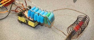
Inverter based welding machine
The most common is a homemade spotter from a welding machine, although it can also be assembled without welding. Spotter is an offshoot of resistance welding. But there are no pliers in it, so the device is considered an analogue of conventional electric arc welding, where current passes through the metal. One contact is attached to the body, and the second is a rod and nozzle.
Do-it-yourself resistance welding from an inverter has two main components:
- Welding inverter,
- Thyristor relay.
Self-assembly is carried out using the following parts:
- Thyristor rated 200 V.
- 122V step-down transformer for relay control via switch.
- 30 A relay.
- Diode bridge.
- Contact group for 220 V.
- Relay switch.
Through a diode bridge, the transformer is connected to the network, and at the same time the thyristor of the electric relay is connected. The transformer supplies power to the control branch of the thyristor circuit.
Assembling the device
Inverter welding machines are a good option for assembling a spotter. The main thing is to configure the device so that a constant current device produces at least 1500 Amperes.
Assembly is carried out in stages:
- Remove the secondary winding from the device, most often there are two of them.
- Set the required number of turns to 1 V. To do this, you can wrap the primary with copper wire and measure the voltage. The resulting figure is divided by the number of turns of wire. The result is the required number of turns.
- With a much smaller cross-section, the tire is divided into several parts and fastened with special electrical tape containing matter. The number of partitions is calculated from the primary indicator. With an indicator of 40 mm2, the tire is divided into four parts.
- Two tires with winding and electrical tape are required. You need to isolate sequentially.
- The resulting busbars are wound on a transformer. This may require a hammer and the help of a second person.
When the required current power is reached, the device is considered ready.
Preparing the transformer
A device such as a spotter involves rewinding the transformer. The process is labor-intensive and considered the most difficult. Winding takes a lot of time, but you can’t do without it. The winding can be of different types. The insulation of the coils can be made of varnished fabric or transformer paper.
A transformer that will provide current generation is difficult to find, but can be made. To do this, you will need a magnetic circuit, which will be the base, with a cross-section of at least 400 mm2. The size is calculated taking into account the placement of the winding.
There are three types of winding placement:
- W-shaped,
- O-shaped,
- Toroidal.
Magnetic cores can be plate or tape. The choice is individual. For the W-shaped type, the primary winding consists of 200 turns, and it will require a wire with a cross-section of 2.5 mm2. The secondary winding has 7 turns, for which you will need a wire with a cross-section of 50 mm2 or a bus of the required cross-section with insulation.
The length of the ends of the secondary wire is calculated for connection to the output terminals, and the primary wire to the electrical circuit of the device. The transformer is impregnated with shellac.
In the electrical circuit drawing there is a supply transformer, the voltage of the secondary winding of which is 12 V. Any other transformer that meets the parameters is also suitable. To control the voltage on the device, it can be equipped with an additional winding.
The thyristor must meet the following parameters: reverse voltage is not less than 220 V, and forward pulse current is not less than 50 A. Diodes are selected according to the same parameters. A 100 ohm resistor and a 25 V 1000 µF capacitor are used.
Sequence of operation of a homemade spotter:
- Turning on the button and discharging the capacitor, briefly turning on the resistor and thyristor.
- Supplying alternating voltage to the primary winding of the transformer through diodes.
- Welding parts and electrode.
- Discharging the capacitor, closing the thyristor and de-energizing the power transformer.
- The work is completed, the capacitor continues to be charged from the transformer for further work.
It is important to remember that thyristors and diodes can be replaced by triacs. A homemade device must be precisely designed for smooth and correct operation, regardless of size and investment
Functionality of serial model spotters
Spotters, mass-produced in production conditions, have a number of popular functions. Among them:
- possibility of welding repair washers;
- welding of a metal electrode followed by pulling out the metal of the part;
- using the device complete with graphite electrodes, which make it possible to perform metal upsetting (heating and subsequent cooling);
- ease of maintenance, ease of operation;
- two modes for performing welding work - constant switching on (this mode uses a carbon electrode) and short-term switching on, which can be adjusted in time (this mode is used for welding repair washers or a metal electrode);
- equipped with a forced cooling system (the design of the device also includes a thermostat, the functions of which include turning off the spotter when it overheats, as well as turning it on when cooling to the required temperature).
One of the variations of factory spotters and related devices for various purposes
Characteristics of commercially produced spotters
Serial models of spotters produced by modern manufacturers have the following technical characteristics.
- The device operates from an electrical network with a voltage of 220 V.
- The frequency of the alternating current in the network from which the spotter is powered is 50–60 Hz.
- The maximum power of the spotter is 10 kW.
- The maximum current value at which welding work can be performed is 1300 A.
- The voltage obtained from the secondary winding of the device is 7.8–9 V.
- The spotter timer allows you to set the time within 0–1.2 seconds.
- It is possible to use two welding modes: spot welding, which uses a timer, and continuous, which can perform both welding and tempering.
- For various types of welding, the productivity of the device has the following values: 15% – spot welding of metal parts, performed at the maximum output power; 75% – carbon welding performed at the minimum output power.
- The pulling force when using a metal electrode is more than 100 kg.
- The pulling force when using a mounting washer is more than 100 kg.
An example of another homemade product
Power supply and its circuit
Transformer winding diagram.
The power supply diagram is shown in Fig. 1. Conventionally, it can be divided into three components:
- power circuit of the primary winding of the step-down transformer;
- a step-down transformer;
- secondary winding with diode bridge and voltage stabilizer.
A surge filter, usually used in switching power supplies, is installed in the primary winding circuit of the transformer. Here it is used to protect the controller chip from impulses created in the mains voltage during operation of the spotter.
Any transformer with a voltage of 220 V/24 V can be used when operating from a 220 V network. When operating from a 380 V network, you need to use an appropriate transformer and a surge filter.
A diode bridge with smoothing capacitors and a voltage stabilizer on the LM2574 chip are connected to the secondary winding. From the output of the microcircuit, a nominal voltage of 5 V is supplied to the output connector X1 through an LC filter chain to eliminate high-frequency interference. The connecting lines marked with a dotted line should be of a minimum length and located as close as possible to the second leg of the IC1 chip.
Figure 1. Power supply diagram.
The voltage at terminal 1 of connector X1 is used by the controller to determine the zero level.
The voltage from terminal 7 of connector X1 is used to start the controller at a positive half-wave of the mains voltage.
A self-made circuit, if there are no errors in the assembly, starts working without additional settings. The presence of a voltage of 5 V will control LED1.
Starter K1 is designed to connect mains voltage when switch S1 is closed.
Instead, you can use a circuit breaker with protection of the required rating or connect the voltage directly, if there are fuses in the supply network.
Methods of working with a spotter
Methods of working using a spotter, which allows you to straighten deformed areas of the car body, even those located in hard-to-reach places, have been worked out by many specialists involved in body repair. Using such a device, various elements of the car body that have been subjected to deformation can be corrected: doors, sills, fenders and other parts. The principle of working with a spotter is based on the fact that the force it creates is directed to the outside of the deformed surface.
When a welding current is applied to the electrode of the machine, a connection occurs with the deformed surface. After this, using an inertial hammer or a special stop, the deformed area is leveled and returns to its original state. The final stages of this process are thorough cleaning of the corrected surface and grinding it. More information about working as a spotter can be seen in the video below.
The technology of work performed using a spotter consists of the following stages:
- cleaning the deformed area of the car body, during which all coatings must be removed from the metal surface;
- connecting the ground wire to the car body;
- connection of fasteners to a deformable area of the body, performed using spot welding;
- grasping the fastener using special tools and devices;
- stretching the deformed section of the body and giving it its original shape;
- removing the fastener from the surface of the body;
- cleaning the straightened surface and preparing it for painting.
In order to skillfully handle a spotter, you must have the skills to perform welding work, as well as strictly follow the operating rules of this device. If you follow these recommendations, then eliminating deformations on the car body will not take much time and effort and will be done with high quality.