12V screwdriver speed controller diagram
The 555 timer is widely used in control devices, for example, in PWM speed controllers for DC motors. Anyone who has ever used a cordless screwdriver has probably heard a squeaking sound coming from inside.
This is the whistling of the motor windings under the influence of the pulse voltage generated by the PWM system. It is simply indecent to regulate the speed of an engine connected to a battery in another way, although it is quite possible. For example, simply connect a powerful rheostat in series with the motor, or use an adjustable linear voltage regulator with a large radiator.
A variant of the PWM controller based on the 555 timer is shown in Figure 1.
The circuit is quite simple and is based on a multivibrator, albeit converted into a pulse generator with an adjustable duty cycle, which depends on the ratio of the charge and discharge rates of capacitor C1.
The capacitor is charged through the circuit: +12V, R1, D1, the left side of the resistor P1, C1, GND. And the capacitor is discharged along the circuit: upper plate C1, right side of resistor P1, diode D2, pin 7 of the timer, bottom plate C1. By rotating the slider of resistor P1, you can change the ratio of the resistances of its left and right parts, and therefore the charging and discharging time of capacitor C1, and, as a consequence, the duty cycle of the pulses.
Figure 1. PWM regulator circuit on a 555 timer
This scheme is so popular that it is already available in the form of a set, as shown in the following figures.
Figure 2. Schematic diagram of a set of PWM regulators.
Timing diagrams are also shown here, but, unfortunately, the part values are not shown. They can be seen in Figure 1, which is why it is shown here. Instead of bipolar transistor TR1, without altering the circuit, you can use a powerful field effect one, which will increase the load power.
By the way, another element has appeared in this diagram - diode D4. Its purpose is to prevent the discharge of the timing capacitor C1 through the power source and load - the motor. This ensures stabilization of the PWM frequency.
By the way, with the help of such circuits you can control not only the speed of a DC motor, but also simply an active load - an incandescent lamp or some kind of heating element.
Figure 3. Printed circuit board of a set of PWM regulators.
If you put in a little work, it is quite possible to recreate this using one of the programs for drawing printed circuit boards. Although, given the small number of parts, it will be easier to assemble one copy using a hinged installation.
Figure 4. Appearance of a set of PWM regulators.
True, the already assembled branded set looks quite nice.
Here, perhaps, someone will ask a question: “The load in these regulators is connected between +12V and the collector of the output transistor. But what about, for example, in a car, because everything there is already connected to the ground, the body, of the car?”
Yes, you can’t argue against the mass; here we can only recommend moving the transistor switch to the gap in the “positive” wire. A possible version of such a scheme is shown in Figure 5.
Figure 6 shows the MOSFET output stage separately. The drain of the transistor is connected to +12V of the battery, the gate simply “hangs” in the air (which is not recommended), a load is connected to the source circuit, in our case a light bulb. This figure is shown simply to explain how a MOSFET transistor works.
In order to open a MOSFET transistor, it is enough to apply a positive voltage to the gate relative to the source. In this case, the light bulb will light up at full intensity and will shine until the transistor is closed.
In this figure, the easiest way to turn off the transistor is to short-circuit the gate to the source. And such a manual closure is quite suitable for checking the transistor, but in a real circuit, especially a pulse circuit, you will have to add a few more details, as shown in Figure 5.
As mentioned above, an additional voltage source is required to turn on the MOSFET transistor. In our circuit, its role is played by capacitor C1, which is charged via the +12V circuit, R2, VD1, C1, LA1, GND.
To open transistor VT1, a positive voltage from a charged capacitor C2 must be applied to its gate. It is quite obvious that this will only happen when transistor VT2 is open. And this is only possible if the optocoupler transistor OP1 is closed. Then the positive voltage from the positive plate of capacitor C2 through resistors R4 and R1 will open transistor VT2.
At this moment, the input PWM signal must be at a low level and bypass the optocoupler LED (this LED switching is often called inverse), therefore, the optocoupler LED is off and the transistor is closed.
To turn off the output transistor, you need to connect its gate to the source. In our circuit, this will happen when transistor VT3 opens, and this requires that the output transistor of the optocoupler OP1 be open.
The PWM signal at this time is at a high level, so the LED is not shunted and emits the infrared rays assigned to it, the optocoupler transistor OP1 is open, which as a result turns off the load - the light bulb.
One of the options for using such a scheme in a car is daytime running lights. In this case, motorists claim to use high beam lamps turned on at full intensity. Most often, these designs are on a microcontroller; there are plenty of them on the Internet, but it’s easier to do it on an NE555 timer.
Screwdriver buttons. — Thoughts of an evil plebeian — LJ
04:55 am - Buttons from a screwdriver.
The screwdriver buttons are PWM with a gs069 microcircuit, which is an analogue of the 555 microcircuit with minor changes.
Button diagram with gs069.
Label/datasheet from gs069. It says that the microcircuit operates at a supply voltage of 4 to 15V, but in reality it operates at a voltage of up to 25V.
Without changes, the Chinese button from aliexpress changes the fill factor from 17% to 63%.
| stage | pulse duration, ms | cycle duration, ms | frequency, kHz | coefficient filling, % |
| 1 | 0,0580 | 0,3428 | 2,9 | 17 |
| 2 | 0,0756 | 0,3628 | 2,8 | 21 |
| 3 | 0,0756 | 0,3420 | 2,9 | 22 |
| 4 | 0,1000 | 0,3668 | 2,7 | 27 |
| 5 | 0,1008 | 0,3356 | 3,0 | 30 |
| 6 | 0,1340 | 0,3704 | 2,7 | 36 |
| 7 | ,1340 | 0,3372 | 3,0 | 40 |
| 8 | 0,1660 | 0,3664 | 2,7 | 45 |
| 9 | 0,1668 | 0,3348 | 3,0 | 50 |
| 10 | 0,1980 | 0,3660 | 2,7 | 54 |
| 11 | 0,1976 | 0,3288 | 3,0 | 60 |
| 12 | 0,2268 | 0,3588 | 2,8 | 63 |
| 13 | 0,2192 | 0,3492 | 2,8 | 63 |
The relationship between frequency and supply voltage for the circuit shown in the figure in the first stage. The frequency value can be calculated using the formula f=1.4kHz+(0.13-0.0029*Vcc)*Vcc. The formula was obtained using the labplot2 program.
The relationship between the coefficients filling and supply voltage for the circuit shown in the figure. Coefficient value filling can be calculated using the formula d=10.3%+(0.66%-0.019*Vcc)*Vcc.
Dependence of frequency on total resistance between pins 4 and 5 at C=500pF. The formula is: f=537*R^-0.75.
Dependence of coefficient filling from the ratio of the resistance connected to pin 4 to the total resistance. Unfortunately, this dependence is expressed by a third-order formula: r%=96.5%+0.17*d-0.034*d^2+0.00023*d^3.
Coefficient adjustment range graphs. filling when the voltage changes on the resistor connected to pin1 of the microcircuit.
The scheme is like this, each graph corresponds to different total values of R2 and R9. Unfortunately, this method of connecting an external regulator only allows you to reduce the coefficient. filling.
Dependence of PWM frequency on coefficient. filling.
The same thing is in relative units, it can be seen that by decreasing the resistance between pin4 and pin5, the PWM frequency becomes more stable. Moreover, as the resistance decreases, the stabilization of the PWM frequency decreases. As a result, there is no point in making the total resistance below 700 kOhm.
The same graphs, but it is not the resistance that changes, but the capacitance of the capacitor. The resistance is 1 MOhm.
On a logarithmic frequency scale, I added a graph for a 10nF capacitance. It can be seen that the PWM frequency depends linearly on the capacitance of the capacitor.
The same thing is in relative frequency units, it is clear that the stability of the PWM frequency does not depend on the capacitance of the capacitor.
An electric drive can be made three times stiffer using positive current feedback. For a better result, it is necessary to add more negative voltage feedback; without it, further deepening of i*r compensation leads to beating. This is my improvement scheme, I don’t recommend using it, since it requires an expensive current sensor, and the result is bad.
Voltage timing diagrams for pin1 (yellow) and pin3 (green) gs069.
Timing diagram of connection between R1 and C1.
Conclusions. 1. It is advisable to replace all resistors associated with the “slider” with more powerful ones, that is, in place of each one, put two resistors (one above the other), since during testing one of them went bad. 2. The voltage to the screwdriver motor armature reaches no more than 2/3 of the battery voltage, if nothing is changed. 3. The gs069 microcircuit operates at a voltage of up to 25V, and not 15 as written on the label. 4. The “trigger” does not use a variable resistor, but a set of series chip resistors. 5. There are a total of thirteen power levels for the screwdriver motor controllers from aliexpress. 6. There is a parasitic PIC for the supply voltage. 7. The PWM period depends linearly on the capacitance of the capacitor. 8. When you change the “trigger” press, not only the duty cycle changes, but also the frequency. 9. Minimum PWM frequency at 50% coefficient. filling. 10. Reducing the total resistance between the 4th and 5th pins of the microcircuit leads to stabilization of the PWM frequency. 11. It is not advisable to reduce the total resistance between the 4th and 5th pins of the microcircuit below 700-500 kOhm, since when this resistance is reduced, the stabilization of the PWM frequency increases slightly. 12. The components of the “trigger mechanism” are configured for maximum efficiency at the expense of reliability and convenience: the total resistance between 4 and 5 is about 1 MOhm, and the PWM frequency is 3 kHz. As a result, the button is sensitive to contamination, since 1 MOhm is the insulation resistance according to PTEEP and the sensitivity of the ear to sound is maximum at 3 kHz, to which PWM is configured. 13. It is difficult to connect an external regulator to the microcircuit, since it can only reduce the coefficient. filling. 14. Positive current feedback can increase low speed torque by 3 times.
Screwdriver speed controller
An electric screwdriver operates either from a 220 V network or from a rechargeable battery. Its power depends on the battery voltage. The screwdriver rotation speed starts at 15,000 rpm. In addition, a powered screwdriver has 2 rotation speeds: a slower one for screwing, a higher one for drilling. The speed control is located inside the power button. The rather miniature size of this tool assembly is achieved using microfilm technology. Its main part is a triac. The operating principle of the regulator is as follows:
- When the button is turned on, an alternating current having a sinusoidal phase is supplied to the control electrode of the triac.
- The triac opens and current begins to pass through the load.
The response time of the triac depends on the amplitude of the control voltage. The greater the amplitude, the earlier the triac is triggered. The amplitude value is set using a variable resistor connected to the start button. The button connection diagram differs in different models. It is possible to connect a capacitor to the speed controller.
Screwdriver force regulator
The force regulator is a clutch that limits the force when the chuck rotates. It is made in the form of a rotating plastic drum. The amount of tightening is adjusted using a digital scale located around the circumference of the drum. By increasing the tightening value, you screw the screw in deeper.
This function will be necessary when working with material products of varying degrees of hardness, since when working with soft material, the body of the self-tapping screw will be easily recessed into it; too high a hardness of the material will contribute to the violation of the geometry of the screw, especially if it is small in size. The ratchet, as the regulator is also called, prevents cutting off the splines of the screws, as well as wear on the screwdriver attachments. The adjusting ring should be tightened in stages, starting with the slightest force. In those screwdrivers in which drilling can be done, the last pictogram on the ring will be in the form of a drill. In this position, maximum torque is achieved.
Screwdriver chuck runout
The runout of the screwdriver chuck indicates that there are problems in the serviceability of the tool gearbox, which is located immediately behind the electric motor. This is another reason why the screwdriver does not work with full impact.
Screwdriver planetary gear parts
The output shaft of this gearbox is the mounting location for the clamping chuck, so if we talk about the runout of the chuck itself, you need to keep in mind the runout of the gearbox shaft. The reasons for this may be the following:
- a) curvature of the gearbox shaft;
- b) wear of gears of the gearbox;
- c) failure of the gearbox shaft support bearing;
- d) the maximum output of the pins on which the satellites of the planetary gear are attached.
All of the above parts are of factory origin and cannot be repaired. The problem of screwdriver chuck runout in this case is solved by replacing the gearbox parts with new ones.
Electronic screwdriver speed control
The rotation speed of the screwdriver attachment can be adjusted mechanically or automatically. Automatic speed control occurs using a processor. You can set the desired operating parameters using the speed selection toggle switch. It is located on top of the body. In many models, speed control is realized through the start button. The stronger the finger pressure on it, the higher the speed will be.
After reading this article, you received information on how to assemble a screwdriver speed controller with your own hands, became familiar with the design of the force regulator, and understood the function of electronic adjustment of the tool. We hope you found the article useful.
Source
DIY screwdriver repair
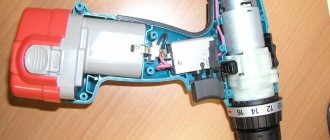
Like any other tool, a screwdriver sometimes requires repair. In such situations, some craftsmen replace this tool with a drill. But at the same time, you should understand that screwing in or unscrewing bolts and screws using a drill is quite inconvenient and has to be done with significant force. Therefore, it is very important for a home craftsman to learn how to troubleshoot a screwdriver with his own hands. To help home craftsmen in this matter, in this article we will talk about the design of a screwdriver, what malfunctions can arise in the operation of this tool, and also how they can be eliminated. Before approaching the issue of tool malfunctions, first of all, it is worth knowing what structural elements it consists of. It is also worth understanding that the basic design of screwdrivers from such popular brands as Makita Makita, Bosch Bosch, Hitachi Hitachi, Aeg does not have significant differences.
Schematic Electrical Diagram of a Screwdriver
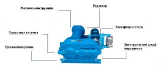
Now you have to use a soldering iron and unsolder the two elements from each other, as shown in the figure. Screwdriver design: 1 - speed controller with reverse, 2 - electric motor, 3 - gearbox.
Resistor Rx sets the highest current.
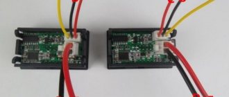
The graph shows how the temperature of the element temperature, the voltage at its terminals voltage and the relative pressure relative pressure change during charging. It can monitor battery parameters and, if necessary, reduce the current automatically. WE MAKE A SIMPLE BATTERY CHARGER with auto shutdown when fully charged
The electrical signal is supplied directly to the engine rotor through the commutator. Next, you need to carefully assemble the screwdriver button, install it in place and test it. When the breakdown occurred, I was on business in Orenburg and therefore contacted the service center for repairs there.
Replaceable battery.
The rather miniature size of this tool assembly is achieved using microfilm technology.
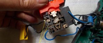
We visually inspect the condition of the button for dirt and damage. repairing a screwdriver, replacing the power button with your own hands
How to repair a screwdriver button if it doesn’t work - detailed instructions
To diagnose and repair a screwdriver, you will need the following tools:
- Crosshead screwdriver;
- Screwdriver with a narrow flat slot.
As a result of active use of any power tool, dirt inevitably accumulates inside its body.
Getting into the control unit, it prevents the “trigger” from moving fully and blocks it.
Therefore, before you go to the store for a new unit, you should try to clean the old one. The carbon deposits formed on the contacts should also be cleaned with fine sandpaper. If the button is not removable, you will have to replace the entire unit.
Stages of diagnostics:
- We disassemble the tool body. To do this, disconnect the battery and unscrew all the screws (they can be hidden behind decorative trims that will have to be removed).
- We check the serviceability of the electric motor. To do this, disconnect the two power wires from the control unit and connect them to the battery contacts (the engine should start).
- We disassemble the screwdriver button. To do this, you need to squeeze out the plastic latches and separate the two parts of the button body.
- We visually inspect the condition of the button for dirt and damage.
- Next, you need to carefully assemble the screwdriver button, install it in place and test it.
VIDEO INSTRUCTIONS » alt=»»>
If cleaning the control unit does not produce results, it is necessary to replace the entire button unit.
To do this you need:
- Disassemble the screwdriver (the process is described above);
- Install a new button in place of the old one;
- Connect the motor to the button terminals (observing polarity in this case is not necessary);
- Assemble the screwdriver, carefully placing the wires in the housing.
It is very important to select a button for a specific screwdriver model, since despite all the external similarity and visual correspondence, the part may not fit into the grooves. As a rule, new buttons are sold complete with battery terminals and a transistor.
Post navigation
Screwdriver force regulator The force regulator is a clutch that limits the force when rotating the chuck. The torque control clutch ensures that rotation stops when the screw is screwed in, as it is accompanied by an increase in rotational resistance.
It is made in the form of a rotating plastic drum. If the speed controller does not work, it means the transistor has burned out and needs to be replaced.
For this purpose, you can gently lift the lid, noting the clear placement of the spare parts on the paper. When replacing, you need to ensure that the capacity and type of power element match.
DC power is supplied from a battery, which is a set of elements housed in one housing. The diagram shows that when the contacts of the electromagnetic relay are closed, the positive voltage through the diode VD7 1N is supplied to the zener diode VD6 through the quenching resistor R6. The gearbox is driven by the rotor sun gear. Using a specialized chip Manufacturers of screwdrivers are trying to reduce prices for their products, often this is achieved by simplifying the charger circuit.
This means you should make sure to clean the device after each use - this is the only way to reduce the risk of failures during operation due to contamination of the tool. If the battery is good, then the next step is to check the power button.
If the elements of the printed circuit board are in good working order and do not raise suspicions, and the charging mode does not turn on, then you should check the SA1 JDD 2A thermal switch in the battery pack. Gearbox parts can be made of both plastic and metal.
By the way, the speed control button and the reverse control button are located in different places, so they will have to be inspected separately. The higher this indicator, the longer the screwdriver works.
In the first case, they are capable of exploding, and in the second, they will no longer be able to restore their capacity. If such elements are found, they should be dismantled and replaced with new ones. Screwdriver battery repair
Main screwdriver malfunctions and their causes
Below is a picture showing the internal structure of the battery device.
Screwdrivers can be equipped with both commutator electric motors and brushless motors (they do not have electric brushes).
If your screwdriver breaks down, then the malfunctions of this device may be the following.
- Device is not working. First of all, the electrical plug or cable may be faulty, the battery may be completely discharged or faulty. This problem can also be caused by burnt-out motor windings, a faulty start button, or worn brushes.
- When the device is operating, it sparks strongly. There may be a malfunction of the armature or motor commutator, as well as problems with the brushes.
- The battery discharges quickly. You will need to check the batteries included in the battery pack using a tester.
- The device turns on spontaneously. Most likely the start button is faulty.
- The engine brake does not work. In this case, it is necessary to replace the button or transistor, since these elements are responsible for braking.
- Chuck backlash. Most often, runout is caused by bending of the gear shaft.
- The ratchet doesn't work. Possible causes: worn ratchet locking blades, broken ratchet pins or springs.
- The cartridge rotates. A malfunction of the gearbox, namely its gears, can cause a situation where the cartridge slips. Also, the malfunction of this unit is the reason that the running motor does not turn the spindle.
- The chuck is jammed and it is impossible to unscrew and remove the drill or bit. As a rule, jamming of the clamping jaws occurs due to insufficient lubrication or breakage of the internal parts of the chuck.
All faults, except for the electrical plug, can only be eliminated after disassembling the device.
Screwdriver body
My screwdriver started spinning spontaneously after 3 weeks, and since it was under warranty, I naturally didn’t think twice and sent it in for repair under warranty. The force of the regulator spring is not enough to hold the ring gear and it “breaks off” from the balls.
In addition, memories are divided according to capabilities and can have: indication; fast charging; different type of protection.
Its operating principle is similar to the KSD series thermal switches. In this case, repairs must be carried out using special tools.
Now you can look inside. Often, to check the functionality of the tool, a tester will not be enough for you, which is due to the fact that the majority of the device’s buttons are equipped with smooth speed control, if a regular tester gives you incorrect data. This scheme can also be used when converting a charger that does not have charging process control units.