Editing methods and requirements for it
Editing methods . Straightening of hull structures is carried out using cold, thermal, non-impact and combined methods.
The cold method of straightening structures is performed in one of the following ways:
- bending of structures on the press;
- stretching welded structures on straightening machines;
- rolling welded joints of structures (panels, shells, pipes, etc.) in sheet straightening machines;
- rolling the zone of welded joints of the structure in special installations and sheet bending rollers;
- by piercing the zone of welded joints of structures.
With the thermal non-impact method, straightening of structures is carried out by heating with the flame of gas burners, the heat of a plasma jet or electric arc, followed by cooling.
Acetylene or its substitutes (propane-butane, natural gas, etc.) are used as flammable gases. In this case, the use of multi-nozzle burners is allowed.
The combined method of straightening structures involves local heating and the use of mechanical compression or unfastening using:
- turnbuckles;
- staples;
- screed;
- jacks;
- cargo, etc.
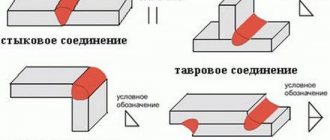
Houses with butt welded joints should be eliminated by gouging the weld along the convex side of the house to a depth of up to two-thirds of its height, followed by welding of the planed areas. If the arrow of the deflection of the houses exceeds the values of three tolerances, the deformation must be eliminated by dissolving these connections, followed by cutting the edges, leveling, joining and welding. For structures made of aluminum alloys, welded joints can be opened when the deflection arrow value exceeds two tolerances.
It is considered acceptable to correct:
- coils with a deflection arrow exceeding the values of three tolerances, for which an incision is made in the center of the coil, followed by cutting the edges, leveling and welding the cut section. Before cutting the coil, holes with a diameter of 3-6 mm should be drilled at the beginning and end of the section;
- single coils along free edges (waviness) on aluminum structures with a deflection arrow of more than two tolerances (at a length of no more than 0.5 m) as a result of cutting them with a circular saw, followed by cutting the edges, leveling and welding;
- coiling of the skin, for which additional reinforcing stiffening ribs are installed, the thickness of which should not exceed 0.6-0.8 of the thickness of the reinforced skin, and the height - 8-10 times the thickness of the rib. No more than one additional stiffener can be installed in one skin cell. In this case, the ribs should not reach a cross set of 10-15 mm. The ends of the stiffening ribs should be cut into a “mustache” (Fig. 1).
Correction of hull structures should be carried out only in cases where general and local deformations arising during their manufacture exceed the permissible values regulated by the drawing and industry standards.
General editing requirements
Straightening of units and structures consists of either lengthening the fibers of welded joints that have received plastic shortening deformations, or shortening the fibers of other sections that have excessive length.
Elongation of the fibers of the material is carried out using the cold method, or the method of thermal jacks, and shortening of the fibers is carried out using the thermal non-stress method using concentrated heating or a combined method using local concentrated heating and mechanical action.
Rice. 1 Shape of the ends of additional stiffeners: a - on structures made of aluminum alloys; b - on steel structures
Editing of units and sections should be performed after completion of all assembly and welding work. Sections of structures in the area of the saturation installation, equipment, foundations and overlying structures must be straightened before the latter are installed.
When editing multi-tiered superstructures, first of all you need to correct the outer walls, and then the floors between them. Editing of superstructures by tiers should be done starting from the first tier.
Correction of corrugated structures is carried out using methods adopted for flat sections. In this case, it is important that the number of heated sections of the structure is minimal, reducing deformations to acceptable values.
Requirements for cold straightening. Welded flat panels without setting are straightened on straightening machines or multi-roll sheet straightening machines and, in exceptional cases, on hydraulic presses. Before straightening, you need to clean the working surface of the rolls from metal dust, scale, dirt and oil. Rolls should not have protruding “ridges” or other defects.
To prevent the welds from collapsing, spacers must be used.
Welded fabrics can also be straightened by piercing the zone of welded joints with a pneumatic hammer with a special chisel or sledgehammer through an ironing hammer (Fig. 2 and 3).
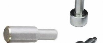
Rice. 2 The working part of the chisel for punching welds of butt (a) and T-joints (b)
Straightening of structures (beams and sections) by plastic bending using the cold method should be done using presses, jacks or weights (Fig. 4).
Rice. 3 Working part of the ironing hammer
The mode of straightening structures using the cold method is regulated by industry standards. The width of the zone for rolling or piercing welded joints when straightening hull structures should be 60–100 mm (30–50 mm on each side of the welded joint). The permissible dimensions of structures (section of beams, height of the set and width of the sections) subjected to straightening by plastic bending using the cold method are determined by the maximum possible force P created by the press, jacks or load, as well as the stability of the elements of the beams and set of sections. The width of the supports and spacer B must be no less than the height of the set H of the section or assembly.
Rice. 4 Scheme of cold straightening of sections with a set of one direction. 1 - punch; 2 - support beams; 3 - section
Requirements for straightening structures using thermal non-impact and combined methods. Hull structures, the local deformations of which do not exceed three values permissible for a given structure, should be corrected using the thermal non-stress method.
When straightening with thermal non-impact and combined methods, heating is recommended to be carried out:
- with strokes (short stripes) - when straightening the sheathing coils and waviness along the free edges;
- stripes along the casing on the back side of the welding set - when editing ribs;
- “triangles” - when correcting the general bending of beams; “spots” - when straightening coils of sheathing of thin-sheet structures (4 mm thick or less).
When the areas to be corrected are heated by the heat of an electric arc, straightening is carried out by surfacing idle rollers or as a result of heating the surface of the structure with idle passes. Craters must be carefully sealed.
In the case of heating structures with the flame of gas burners, a plasma jet, or an electric arc, the heat source moves in a straight line or zigzag at a constant speed.
Thermal straightening with local heating
It is based on the development of plastic deformation by compression of stretched sections of the structure. When straightening with this method, the stretched part of the deformed part is usually heated.
details. Heating is carried out in separate areas. In this case, the expansion of the metal is prevented by the cold parts of the part surrounding it. In these areas, the metal experiences plastic deformation due to compression and shortening of the stretched metal fibers. During subsequent cooling, these areas contract and straighten the product. Thermal straightening is used mainly to eliminate warping deformations of sheet structures and eliminate bending of beam structures. When straightening bulges in sheet parts, the convex part is heated at separate points in a checkerboard pattern. Each heated area tends to expand, but due to resistance from the surrounding cold metal, plastic compressive deformations occur in it.
After cooling, the diameter of the heated circle decreases, which leads to the disappearance of the bulge. Heating can be done with a gas torch, electric arc, carbon electrode, or on spot welding machines. Straightening is accelerated by combining local heating with the application of static loads using special straightening devices.
2. Thermal straightening with general heating (annealing)
It is also produced in special straightening devices, in which the structure is fixed in the desired position with preload in a rigid device. Then the device with the product is loaded into the oven and subjected to general heating. The heated metal is plastically deformed in the device and, upon subsequent cooling, retains its given shape. This straightening can be combined with a general heat treatment operation.
designs. However, this method requires the use of expensive devices made from scarce materials, so it is used, as a rule, in cases where the product is welded from a high-strength material and it is very difficult to get rid of deformations.
Cold mechanical straightening
It is produced with the application of static, shockless loads. For the same purpose, hand presses, special straightening devices, steel punches for compression on mechanized presses, as well as rolling on three-roll mills or stretching on special machines are used. Hydraulic leveling presses and specialized straightening machines are used for straightening large-sized welded assemblies. Thus, the mushroom shape of welded I-beams - the deformation of the flanges resulting from shrinkage of the welds - is straightened using a specialized machine.
Welded cylindrical shells are straightened on three- and four-roll bending machines
For thin-walled vessels, rolling and forging of welds on specialized machines is used. Rolling is carried out by rollers, and forging is carried out by a high-speed pneumatic impact device. In this case, the weld metal is deposited along its thickness, resulting in its expansion in the longitudinal and transverse directions. This leads to a slight elimination of transverse shrinkage and a significant or complete elimination of longitudinal deformations due to shortening of the welding zone. In the same way, it is possible to eliminate bulges in sheet parts by forging from the edges of the part and moving to its center.
Thermo-mechanical straightening
It consists of combining local heating with the application of a static load, bending the structural element to be corrected in the desired direction. This load can be created by jacks, presses or other devices. The use of additional heating helps reduce the effort required to eliminate deformations. This straightening method is usually used for rigid welded assemblies.
Metal diffusion welding
Diffusion welding is carried out in the solid state of the metal at elevated temperatures with the application of a compressive force to the welding site. The process of welding metal in the solid state at elevated temperatures proceeds fundamentally in the same way as during cold welding. At the initial stage of the process, conditions are created at the interface between two parts for the formation of metallic bonds. From the theory of the formation of a welded joint during cold welding, it is known that in order for metallic bonds to appear at the interface line, it is necessary to ensure close contact of the welded surfaces and create conditions for the removal of surface films of oxides, liquids, gases and various types of contaminants.
The use of elevated temperatures during diffusion welding leads to a decrease in the metal’s resistance to plastic deformation. As a result, the protrusions on the metal present in the actual contact zone are deformed under significantly lower loads, which facilitates the approach of metal atoms over the entire area of the welded surface.
Removing surface films and preventing the possibility of their formation during the welding process is achieved by using vacuum protection and thorough preliminary cleaning of the welded surfaces. Thus, the first stage of the diffusion welding process, as well as cold welding, is based on the formation of metallic bonds on the metal surfaces to be welded when they are heated in a vacuum using a compressive force.
At the second stage of the diffusion welding process, processes of mutual diffusion of atoms of the metals being welded occur. These processes lead to the formation of intermediate layers that increase the strength of the welded joint. However, in some cases the formation of intermediate layers is undesirable.
A diagram of the vacuum diffusion welding process is shown in Fig. 33. The product to be welded 2 and a heater 3 are placed in a vacuum cooled chamber 1. To compress the parts during the welding process, a compression mechanism is used, consisting of a rod 5 and a loading mechanism 6, the rod passes through a vacuum seal or bellows 4. Welding occurs in a vacuum of 10~3 — 10~5 mm Hg. Art. (133 10-3-133.1(105 N/m2).
After pumping out air from the chamber, the product is usually heated by heating. h. to welding temperature. To obtain a high-quality connection, it is necessary to ensure uniform heating of the welded product over the entire cross-section.
The compression force is applied after the temperature has equalized and is maintained constant throughout the entire process. Technological techniques with varying pressure during the welding process are also known. The duration of exposure under load depends on the properties of the metal being welded, the pressure and other factors and can reach tens of minutes.
Fig.33. Installation diagram for diffusion welding in vacuum
Fig.34. Dependence of the strength of the welded joint (steel 50) on the welding temperature (welding time 5 min) and pressure during the welding process: 1 - 0.5 kgf/mm2; 2 - 1 kgf/mm2; 3 - 2 kgf/mm2; 4 - 5 kgf/mm2
The pressure also depends on the properties of the metal, welding temperature and other factors and varies from 0.3 to 10 kgf/mm2 (2.9–98 MN/m2). Typically, when cooling parts, the compressive force is removed when the temperature reaches 100–400°C (373–673 K). Premature removal of the compressive force when cooling parts in some cases leads to destruction of the welded joint.
The influence of temperature in the range of 800-1100 ° C (1073-1373 K) on the strength of a joint made of steel 50 at various pressures: 0.5; 1.2 and 5 kgf/mm2 are shown in Fig. 34. Welding duration 5 minutes, vacuum 10-3 mm Hg. Art. (133-10-3 N/m2). Curve 1 shows that when the temperature increases from 800 to 900 ° C (from 1073 to 1173 K), the strength of the connection increases by 2 times, and when the temperature increases to 1100 ° C (1373 K) - by 3 times. To a slightly lesser extent, the temperature has an effect at a pressure of 1 kgf/mm2 (9.8 MN/m2). At a pressure of 2 and 5 kgf/mm2 (19.6 and 49.0 MN/m2), the strength of the connection increases only up to a temperature of 1000 ° C (1273 K). At a temperature of 1100° C (1373 K), a slight decrease in the strength of the connection is observed.
With increasing pressure (Fig. 35) from 0.5 to 2 kgf/mm2 (from 4.9 to 19.6 MN/m2), the strength of the connection increases significantly for 800, 900, 1000, 1100°C (1073, 1173, 1273 , 1373 K). A further increase in pressure from 2 to 5 kgf/mm2 (from 19.6 to 49.0 MN/m2) has little effect on the strength of the connection. The change in joint strength with increasing pressure to 2 kgf/mm (19.6 MN/m2) and higher can be explained mainly by an increase in the area of actual contact between the surfaces being connected.
Rice. 35. Dependence of the strength of the welded joint (steel 50) on pressure and temperature (welding time 5 min): 1 - T = 800 ° C; 2 T - 900° C; 3 - T = 1000° C; 4-T=1100°С
Increasing the temperature with constant welding duration and other equal conditions increases the strength of the joint. The duration of welding similarly affects all strength characteristics (Fig. 36). The dependence of the strength of the resulting joint made of steel 45 on temperature and pressure is shown in Fig. 37 surface, which, when intersecting with the horizontal p-T plane, forms a weldability boundary.
Fig.36. Dependence of the strength of the welded joint on the welding duration: 1 - BTI titanium alloy; 2 - steel 45; 3 — kovar N28K18; 4 - copper Ml
Fig.37. Diagram of the dependence of the strength of a welded joint made of steel 45 on temperature and pressure
Fig.38. Dependence of the strength of welded joint samples on the welding duration (p = 2 kgf/mm2)
As the welding duration increases, the strength of the welded joint increases (Fig. 38); an increase in the welding duration beyond the optimal one has virtually no effect on the strength of the welded joint. However, an excessive increase in holding time even leads to a decrease in the strength of the welded joint. The duration of the process has a similar effect on ductility, elongation and impact strength.
The final temperature of cooling samples in vacuum has a significant effect on strength and ductility (Fig. 39); welding mode: T = 1000° C (1273 K), p = 2 kgf/mm2 (19.6 MN/m2), t = 5 min. Cooling welded parts to lower temperatures under compressive pressure in a vacuum chamber helps to increase the strength and ductility of the joint.
Fig.39. Dependence of the strength and ductility of a structural steel connection on the final cooling temperature in a vacuum
Fig.40. Dependence of the strength of a welded joint made of steel 45 on the cleanliness of surface treatment before welding
The degree of vacuum in the vacuum chamber is important for diffusion welding. At a temperature of 1000° C (1273 K), p = 2 kgf/mm2 (19.6 MN/m2), t = 5 min, the strength of the connection increases significantly with increasing vacuum up to 10-1 mm Hg. Art. (133-10-1 N/m2), with a further increase in vacuum there is only a slight increase in the strength of the welding zone.
Methods of preparing and treating the surfaces of welded parts have a great influence on the strength of the joint during diffusion welding in a vacuum (Fig. 40). During roughing, the pressure is not enough to ensure high strength of the welded joint.
Editing structures with general and local deformations
Editing structures with general deformations . Editing of welded beams, assemblies and foundations. If the general bending of the beams exceeds the permissible norms, they should be straightened before installation on the sections using the cold method on presses. It is allowed to straighten welded beams by heating individual sections along the convex side of the collar or wall (Fig. 7).
Rice. 7 Scheme for straightening the longitudinal bending of welded and rolled beams: a, c, d - in the case of bending to a flange; b, d, f - when bending onto the wall. 1, 2, 3… - heating order
When straightening the beams of the set using the combined method, additional metal replenishment should be done using a load, fastenings or other devices (Fig. 8).
Rice. 8 Scheme of straightening welded T-beams by heating with forced landing. 1 - bracket; 2 — assembly clamp; 1′, 1″, 2′, 2″, 3′, 3″… – heating order
If the height of the T-beam wall is more than twenty-five times its thickness, before heating it is necessary to install the “fish” on brackets along the free edge of the wall (Fig. 9). Deformations of the beam can also be eliminated by hammering with a sledgehammer using copper-plated steel support. When the beam is simultaneously bent in two planes (in the plane of the wall and in the plane of the girdle), straightening should begin in the plane of the wall.
Rice. 9 Scheme for straightening welded T-beams with a high wall. 1 - bracket; 2 - wedge; 3 - “fish”; 1′, 2′, 3′. . . - heating sequence
The collapse of the wall relative to the girdle or rib is corrected by heating in strips along the wall from the side of an obtuse angle at a distance of 20-30 mm from the weld. Stops, couplers and other devices should be used (Fig. 10, b).
Rice. 10 Scheme for straightening the wall of a welded T-beam: a - by applying a weld along a pre-planed groove; b - heating with an elastic bend of the wall. 1 - groove in the seam; 2 - wedge; 3 - bracket; 4 — lanyards (ties); 5 - heating section (from the obtuse angle side)
In exceptional cases, it is allowed to correct the obstruction of the wall relative to the girdle by applying a seam from the side of an obtuse angle. In this case, it is necessary to cut a groove in the weld seam with a gas or air-arc planer to a depth of no more than two-thirds of the wall thickness (Fig. 10, a), then thoroughly clean it and weld it.
Straightening of the simplest welded assemblies is carried out using the cold method on a press. The simplest welded foundations must be straightened using a cold method on a press or local heating, similar to straightening T-beams. The location and number of heating spots is selected in each case depending on the rigidity of the foundation and the arrow of its bend (Fig. 11).
Rice. 11 Scheme of straightening welded foundations. 1, 2, 3… - heating order
Editing the general bending of sections. Straightening of sections that have received general bending deformation can be done using cold, thermal, non-stress, or combined methods.
The general bending of small sections set in one direction should be corrected using the cold method, by bending them back plastically using weights, jacks or pressure beams.
When straightening the general bending of structures using thermal non-impact or combined methods, local heating of the set or panel is used, depending on the type of structure and the nature of the deformation.
Recommended reading: How and where are composite parts of hull structures made?
Straightening of sections that have received a bend towards the set (“collapse”) should be done by local heating of the skin in strips perpendicular to the bending plane. In this case, it is necessary to combine the correction of the coiling and ribbing of the section panel. Heating strips must be placed along the sheathing on the reverse side of the welding of the set (in the case of ribbed skin panel) and between the set (in the case of coiled skin panel).
For sections that have been bent in two mutually perpendicular directions, heating by strips should be carried out in these directions. Crossing heating strips is not permitted. First of all, you need to correct the largest bend. To do this, the heating strips are placed perpendicular to the bending plane.
Straightening of the transverse “blockage” of the bottom sections is carried out by heating strips along the outer skin on the reverse side of the welding of the vertical keel, stringers and longitudinal stiffeners (Fig. 12). Along with heating the casing, heating of sections of the set is allowed.
Rice. 12 Scheme for straightening the transverse “blockage” of the bottom section. 1 - heating areas; 2 — position of the section before editing; 3 - the same after editing
Correction of the “camber” of the bottom sections with the second bottom flooring is carried out as a result of heating the second bottom flooring strips from the reverse side of the welding set (Fig. 13).
Rice. 13 Scheme for straightening the transverse camber of the bottom section. 1 - heating areas; 2 — position of the section before editing; 3 - the same after editing; 1′, 2′, 3′… – heating order
Straightening of flat sections that have received a bend towards the skin (“camber”) should be done by local heating of a set parallel to the bending plane (Fig. 14). Heating areas in one direction must be located in the same cross-sectional plane of the structure.
Rice. 14 Scheme for straightening the camber of the side section. 1 - heating areas; 2 — position of the section before editing; 3 - the same after editing; 1′, 1″, 2′, 2″, 3′, 3″. . . – heating sequence; I, II - sequence of heating series
Correction of the general bend of rudder stays, stabilizers and similar structures should be done by heating with strips along the skin on the back side of the welding kit. Heating should begin on the reverse side of the weld set, perpendicular to the plane of the major bend.