Purpose and principle of operation
Using voltage regulators, you can change not only the brightness of incandescent lamps, but also the rotation speed of electric motors, the temperature of the soldering iron tip,
and so on. These devices are often called power regulators, which is not entirely correct. Devices designed to regulate power are based on PWM (pulse width modulation) circuits.
This allows you to obtain different pulse repetition rates at the output, the amplitude of which remains unchanged. However, if a voltmeter is connected in parallel to the load in such a circuit, the voltage will also change. The fact is that the device simply does not have time to accurately measure the amplitude of the pulses.
It should be noted that voltage regulators will be most effective when working with resistive loads, such as incandescent lamps. But using them to connect to an inductive load is impractical. The fact is that the inductive current is much lower compared to resistive current.
Assembling a homemade dimmer is quite simple. This will require some basic knowledge of electronics and a few parts.
Based on triac
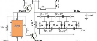
Such a device operates on the principle of phase shift of key opening. Below is the simplest triac-based dimmer circuit:
Structurally, the device can be divided into two blocks:
- A power switch, in the role of which a triac is used.
- Unit for creating control pulses based on a symmetrical dinistor.
A voltage divider is created using resistors R1-R2
It should be noted that resistance R1 is variable. This allows you to change the voltage in line R2-C1
A DB3 dinistor is connected between these elements. As soon as the voltage indicator on capacitor C1 reaches the opening threshold of the dinistor, a control pulse is applied to the switch (triac VS1).
Thyristor based
These partings are also quite effective, and their patterns are not very complicated. The role of the key in such a device is performed by a thyristor. If you carefully study the circuit diagram of the device, you will immediately notice the main difference between this circuit and the previous one - for each half-wave, its own switch with a control dinistor is used.
The operating principle of the thyristor device is as follows:
- When a positive half-wave passes through line R5-R4-R3, capacitor C1 is charged.
- After reaching the switching threshold of dinistor V3, it is triggered, and electric current flows to switch V1.
- When a negative half-wave passes, a similar situation is observed for the line R1-R2-R5, the control dinistor V4 and the key V2.
Capacitor regulators are also used in everyday life. However, unlike semiconductor devices, they do not allow smooth voltage changes. Thus, thyristor and triac circuits are best suited
.
Finding all the parts needed to make the regulator is not difficult. However, you don’t have to buy them, but can be removed from an old TV or other radio equipment. If desired, you can make a printed circuit board based on the selected circuit, and then solder all the elements into it. The parts can also be connected using regular wires. The home master can choose the method that seems most attractive to him.
Both devices discussed are quite easy to assemble, and you don’t need to have serious knowledge in the field of electronics to complete all the work. Even a novice radio amateur can make a 220V voltage regulator circuit with his own hands. At a low cost, they are practically in no way inferior to their factory counterparts.
How it works?
The information described below is valid for most schemes. Letter designations will be taken in accordance with the first circuit of the thyristor regulator
A thyristor power regulator, the operating principle of which is based on phase control of the voltage value, also changes the power. This principle lies in the fact that under normal conditions the load is affected by the alternating voltage of the household network, changing according to a sinusoidal law. Above, when describing the operating principle of a thyristor, it was said that each thyristor operates in one direction, that is, it controls its own half-wave from a sine wave. What does it mean?
Read also: High-speed steels, hard alloys and their applications
If you periodically connect a load using a thyristor at a strictly defined moment, the value of the effective voltage will be lower, since part of the voltage (the effective value that “falls” on the load) will be less than the mains voltage. This phenomenon is illustrated in the graph.
The shaded area is the area of stress that is under load. The letter “a” on the horizontal axis indicates the opening moment of the thyristor. When the positive half-wave ends and the period with the negative half-wave begins, one of the thyristors closes, and at the same moment the second thyristor opens.
Replacing a triac in a dimmer
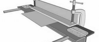
Hollow rivets can be removed using a 90° drill bit or side cutters. But in order not to damage the radiator, this must be done from the side where the triac is located.
The radiators, made of very soft aluminum, were slightly deformed when riveted. Therefore, I had to sand the contact surfaces with sandpaper.
- Screw M2.5x8.
- Spring washer (grower) M2.5.
- Washer M2.5 – fiberglass.
- Triac case.
- Gasket – fluoroplastic 0.1mm.
- Nut M2.5.
- Washer M2.5.
- Tube (cambric) Ø2.5x1.5mm.
- Washer M2.5.
- Radiator.
Since I used a triac that does not have galvanic isolation between the electrodes and the contact pad, I used the old proven isolation method. The drawing shows how it is implemented.
And these are the same parts of the galvanic isolation of the triac in its natural form.
To prevent the radiator wall from pressing through at the location where the triac is attached, a washer was placed under the screw head. And most of the head of the screw itself was ground off so that it would not cling to the handle of the potentiometer and power regulator.
This is what a triac isolated from the radiator looks like. To improve heat dissipation, thermal conductive paste KPT-8 was used.
What's under the dimmer housing?
Back in action.
Using the regulator in everyday life and safety precautions
It must be said that this circuit does not provide galvanic isolation from the network, so there is a danger of electric shock. This means that you should not touch the regulator elements with your hands. An insulated housing must be used. You should design the design of your device so that, if possible, you can hide it in an adjustable device and find free space in the case. If the adjustable device is located permanently, then in general it makes sense to connect it through a switch with a dimmer. This solution will partially protect against electric shock, eliminate the need to find a suitable housing, has an attractive appearance and is manufactured using an industrial method.
Assembling the device
We will not describe all standard assembly actions; we will only note the main points. The transistor must be placed on a heat sink. Why? Because the circuit is linear and at high currents the transistor will get very hot. What is the radiator made of? It can be made from a regular aluminum corner and attached directly to the power supply fan. And, despite the fact that the radiator is quite small in size, thanks to the intense airflow it will cope with its task perfectly.
A transistor is screwed to the radiator through thermal paste; in this circuit it uses a field-effect, N-channel IRFZ44 with a maximum current of 49 A. Since the radiator is isolated from the main board and case, the transistor is screwed directly without insulating spacers.
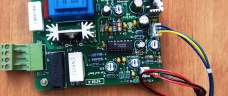
The stabilizer board is fixed to the same aluminum corner through a brass stand. To regulate the output current, a 5 kOhm variable resistor is used. The wires are secured with plastic ties to prevent them from dangling.
As a result, you should get the following connection diagram for this stabilizer for the charger.
The power supply can be absolutely anything, either a computer power supply or a regular transformer. The cord used to connect to the outlet is a regular computer one.
All is ready. You can now use such an adjustable voltage stabilizer for the charger. It should be noted that the circuit is simple and inexpensive: it simultaneously functions as a stabilizer and a charger.
Thyristor circuits
You can regulate the total power of the soldering iron quite simply if you use analog or digital soldering stations for this. The latter are quite expensive to use, and it is quite difficult to assemble them without much experience. While analog devices (considered to be essentially total power regulators) are not difficult to create yourself.
A fairly simple circuit of the device that will help regulate the power indicator on the soldering iron.
- VD - KD209 (or similar in its general characteristics).
- R 1 - resistance with a special rating of 15 kOhm.
- R2 is a resistor that has a special AC current rating of about 30 kOhm.
- Rn is the total load (in this case a special pendulum will be used instead).
Such a regulation device can control not only the positive half-cycle; for this reason, the power of the soldering iron will be several times less than the nominal one. Such a thyristor is controlled using a special circuit, which carries two resistances, as well as a capacitance. The charging time of the condensate (it will be regulated by a special resistance R2) affects the duration of opening of such a thyristor.
How does a thyristor do its job?
A thyristor is a controlled semiconductor device that is capable of quickly conducting current in one direction. The word controlled means a thyristor for a reason, since with its help, unlike a diode, which also conducts the total current to only one pole, you can select a separate moment when the thyristor begins the process of conducting current.
The thyristor has three current outputs at once:
To allow current to flow through such a thyristor, the following conditions must be met: the part must be located on the circuit itself, which will be under general voltage, and the required short-term pulse must be applied to the control part of the electrode. Unlike a transistor, controlling such a thyristor will not require the user to hold the control signal.
But all the difficulties of using such a device will not end there: the thyristor can be easily closed by interrupting the flow of current into it through the circuit, or by creating a reverse anode-cathode voltage. This will mean that the use of a thyristor in DC circuits is considered quite specific and in most cases completely unreasonable, and in AC circuits, for example, in a device such as a thyristor regulator, the circuit is created in such a way that the condition for closing the device is fully ensured . Any given half-wave will completely cover the corresponding section of the thyristor.
is most likely difficult for you to understand the diagram of its structure . But, there is no need to be upset - the process of functioning of such a device will be described in more detail below.
Scheme number 1
There was a stabilized switching power supply that gave an output voltage of 17 volts and a current of 500 milliamps. A periodic change in voltage was required in the range of 11 - 13 volts. And the well-known voltage regulator circuit on one transistor coped with this perfectly. I added only an indication LED and a limiting resistor to it. By the way, the LED here is not only a “firefly” signaling the presence of output voltage. With the correct value of the limiting resistor, even a small change in the output voltage is reflected in the brightness of the LED, which provides additional information about its increase or decrease. The output voltage could be changed from 1.3 to 16 volts.
KT829, a powerful low-frequency silicon compound transistor, was installed on a powerful metal radiator and it seemed that, if necessary, it could easily withstand a heavy load, but a short circuit occurred in the consumer circuit and it burned out. The transistor has a high gain and is used in low-frequency amplifiers - you can really see its place there and not in voltage regulators.
On the left are removed electronic components, on the right are prepared for replacement. The difference in quantity is two items, but in terms of the quality of the circuits, the former and the one that was decided to be collected, it is incomparable. This begs the question: “Is it worth assembling a scheme with limited capabilities when there is a more advanced option “for the same money”, in the literal and figurative sense of this saying?”
Thyristor voltage regulator circuit
Element rating table
- C1 – 0.33 µF voltage not lower than 16V;
- R1, R2 – 10 kOhm 2W;
- R3 – 100 Ohm;
- R4 – variable resistor 33 kOhm;
- R5 – 3.3 kOhm;
- R6 – 4.3 kOhm;
- R7 – 4.7 kOhm;
- VD1 .. VD4 – D246A;
- VD5 – D814D;
- VS1 – KU202N;
- VT1 – KT361B;
- VT2 – KT315B.
The circuit is built on a domestic element base; it can be assembled from those parts that radio amateurs have had for 20-30 years. If the thyristor VS1 and diodes VD1-VD4 are installed on the corresponding coolers, then the thyristor voltage regulator will be capable of delivering 10A to the load, that is, with a voltage of 220 V, we are able to regulate the voltage on a load of 2.2 kW.
The device has only two power components: a diode bridge and a thyristor. They are designed for a voltage of 400V and a current of 10A. The diode bridge converts the alternating voltage into a unipolar pulsating one, and the phase regulation of the half-cycles is carried out by the thyristor.
A parametric stabilizer consisting of resistors R1, R2 and a zener diode VD5 limits the voltage supplied to the control system at 15 V. Connecting resistors in series is necessary to increase the breakdown voltage and increase power dissipation.
At the very beginning of the half-cycle of the alternating voltage, C1 is discharged and at the connection point R6 and R7 there is also zero voltage. Gradually, the voltages at these two points begin to increase and the lower the resistance of resistor R4, the faster the voltage at the emitter of VT1 will surpass the voltage at its base and open the transistor. Transistors VT1, VT2 make up a low-power thyristor. When a voltage appears at the base-emitter junction VT1 greater than the threshold, the transistor opens and opens VT2. And VT2 unlocks the thyristor.
The presented circuit is quite simple, it can be transferred to a modern element base. It is also possible to reduce the power or operating voltage with minimal modifications.
Read also: Threading dies dimensions
25 thoughts on “Thyristor voltage regulator simple circuit, principle of operation”
Since we are talking about electrical angles, I would like to clarify: when “a” is delayed to 1/2 half-cycle (up to 90 electrical degrees), the voltage at the output of the regulator will be equal to almost the maximum, and will begin to decrease only when “a” > 1/2 (>90). It’s written in red on gray on the graph! Half a half cycle is not half a voltage. This circuit has one advantage - simplicity, but the phase on the control elements can lead to difficult consequences. And the interference induced in the electrical network by the thyristor cutoff is considerable. Especially under heavy load, which limits the scope of application of this device. I see only one thing: adjusting the heating elements and lighting in storage and utility rooms.
In the first picture there is an error, 10 ms should correspond to a half-cycle, and 20 ms should correspond to the period of the mains voltage. Added a graph of the adjustment characteristics when operating on an active load. Apparently you are writing about the control characteristic when the load is a rectifier with a capacitive filter? Then yes, the capacitors will be charged at maximum voltage and the control range will be from 90 to 180 degrees.
I collected similar circuits... they all work flawlessly, but I like them better on KT 117
Not everyone has deposits of Soviet radio components. Why not indicate “bourgeois” analogues of old domestic semiconductor devices (for example, 10RIA40M for KU202N)?
The KU202N thyristor is now being sold for less than a dollar (I don’t know if it’s in production or if old stocks are being sold off). And the 10RIA40M is expensive; on Aliexpress they sell it for about $15 plus shipping from $8. It makes sense to use 10RIA40M only when you need to repair a device with KU202N, but KU202N cannot be found. For industrial use, thyristors in TO-220, TO-247 packages are more convenient. Two years ago I made an 8 kW converter, so I bought thyristors for $2.5 (in a TO-247 package).
This is what was meant, if the voltage axis (for some reason marked P) is drawn as in the 2nd graph, then it will become clearer with the degrees, periods and half-cycles given in the description. All that remains is to remove the sign of the alternating voltage at the output (it has already been rectified by the bridge) and my meticulousness will be completely satisfied. KU202N is now sold on radio markets for really pennies, and in the 2U202N version. Anyone in the know will understand that this is military production. Probably the warehouse repair parts, which have expired, are being sold out.
On the market, if you take it from hand, they can also include a soldered part among the new ones. You can quickly check a thyristor, for example KU202N, with a simple pointer tester turned on to measure resistance on a scale in units of ohms. We connect the anode of the thyristor to the plus, the cathode to the minus of the tester, in a working KU202N there should be no leakage. After the control electrode of the thyristor is shorted to the anode, the ohmmeter needle should deflect and remain in this position after opening. In rare cases, this method does not work, and then for testing you will need a low-voltage power supply, preferably an adjustable one, a flashlight bulb, and a resistance. First, we set the voltage of the power supply and check whether the light bulb is lit, then we connect our thyristor in series with the light bulb, observing the polarity. The light bulb should light up only after a short-circuit of the thyristor anode with the control electrode through a resistor. In this case, the resistor must be selected based on the rated opening current of the thyristor and the supply voltage. These are the simplest methods, but perhaps there are special devices for testing thyristors and triacs.
can withstand the test for a short time without resistance
The output voltage is not rectified by the bridge. It is rectified only for the control circuit.
The output is variable, the bridge rectifies only for the control circuit.
I would not call voltage regulation, but power regulation. This is a standard dimmer circuit that almost everyone used to assemble. And they turned down the radiator to the thyristor. In theory, of course it is possible, but in practice I think it is difficult to ensure heat exchange between the radiator and the thyristor to provide 10A.
What difficulties does KU202 have with heat transfer? Screwed the end bolt into the radiator and that’s it! If the radiator is new, or rather, the threads are not loose, you don’t even need to lubricate the KTP. The area of a standard radiator (sometimes included) is precisely designed for a load of 10 A. No theory, just practice. The only thing is that the radiators should have been located in the open air (according to the instructions), and with such a network connection it is fraught. Therefore, we close it, but install the cooler. Yes, we don’t lean the pavements against each other.
I completely agree with regulating the power delivered to the load. The thyristor, of course, does not need to be put in extreme modes. And so, my favorite scheme. even used successfully for adjustment in the primary winding of a transformer.
Tell me, what kind of capacitor C1 is -330nF?
It would probably be more correct to write C1 - 0.33 µF; you can set ceramic or film to a voltage of at least 16V.
All the best! At first I assembled circuits without transistors... One thing was bad - the control resistance got hot and the layer of graphite track burned out. Then I collected this diagram on CT. The first one was unsuccessful - probably due to the high gain of the transistors themselves. I assembled it on MP with a gain of about 50. It worked without problems! However, there are questions...
I also assembled without transistors, but nothing was heated. It was two resistors and a capacitor. Later I also removed the capacitor. In fact, there was an alternator between the anode and the control, and of course a bridge. I used it to adjust the power of the soldering iron, both at 220 volts and and to the primary transformer for a 12 volt soldering iron and everything worked and did not get hot. Now it is still in the closet in good condition. You may have had a leak in the capacitor between the cathode and the control for a circuit without transistors.
I assembled it on MP with a gain of about 50. It works! But there were more questions...
The values of R4 and R5 are clearly mixed up. Has anyone assembled the circuit in hardware?
Can you be more specific about the diode bridge? How are the diodes directed?
plus to the right, minus to the left))
The schedule is wrong. At 90 degrees *power* will be half. And the voltage will be one root of two less than the original one. Like from 220 there will be 155, not 110.
Is it possible to replace the transistors with a DB3 dinistor (costs 4 rubles)? Give me the diagram please
...and if it is, adjust the fan speed?, (but there is an inductive load,... that’s a question).
DIY soldering iron power regulator: proven working circuits (6 pcs)
Not everyone likes to buy unknown things. And some people find it more pleasant to make a soldering iron power regulator with their own hands, because this is also experience. Most circuits are assembled using triacs and thyristors; now they are easier to find than transistors. They are also easier to work with, since they are either open or closed, which allows you to make circuits simpler.
Choose any case
Simple thyristor circuits
When choosing a power regulator circuit for a soldering iron, two things are important: power and parts availability. The soldering iron power regulator presented below is assembled using widely used parts that are not a problem to find. The maximum current is 10 A, which is more than enough to perform any kind of work and for soldering irons with a power of up to 100 W. The thyristor in this circuit is used KU202n
Pay attention to the bridge connection. There are many circuits with connection errors
This option is working. Tested more than once.
Temperature controller circuit for a soldering iron using a thyristor
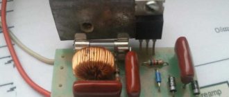
When assembling the circuit, be sure to place the thyristor on the radiator; the larger it is, the better. The circuit is simple, but when it is turned on, it creates interference. You can’t listen to the radio nearby, and to remove interference, we connect a 200 pF capacitor in parallel with the load, and a choke in series. The choke parameters are selected depending on the regulated load, but since soldering irons are usually no more than 80-100 W, the choke can be made at 100 W. To do this, you will need a ferrite ring with an outer diameter of 20 mm, on which about 100 turns are wound with a wire with a cross-section of 0.4 mm².
Another drawback of the diagram translated above is that the soldering iron “itches” noticeably. Sometimes you can put up with this, sometimes you can’t. To eliminate this phenomenon, you can select the parameters of capacitor C1 so that when the variable resistor is set to maximum, the connected lamp barely glows.
On other elements but also without interference
The above regulator can be used for any load. Let's give another analogue, but using a different element base. You can regulate not only the power/temperature of the soldering iron, but also any other load with a small inductive component.
A modified circuit for regulating the power of a soldering iron and any other load with the ripple effect eliminated
There is pulsation here, but its frequency is high and it will not be perceived by our vision. So it can be used not only as a dimmer for a soldering iron, but also to regulate the light from a regular incandescent lamp. Is a diode bridge needed to regulate the heating power of a soldering iron? It won't hurt, but it's not necessary.
On a thyristor with high sensitivity
This circuit allows you to smoothly change the temperature of the soldering iron from 50% to 100%. There are two indicators - power and power. The power presence LED always lights up when turned on, but at 75% power the glow is brighter. The power indicator changes the intensity of the glow depending on the operating mode.
Power regulator for soldering iron without interference
In order for the regulator to fit into the case of a mobile phone charger, resistances are used of SMD type (1206). All resistors are installed on the board, except for R 10. Some can be composite (we assemble the required value from series-connected resistors).
For normal operation of the circuit, a sensitive thyristor (with a low control current) and a low state holding current (about 1 mA) is required. For example, KT503 (designed for voltage 400 V, control current 1 mA). The rest of the element base is indicated in the diagram.
If assembled, but the voltage is not adjustable
If the assembled regulator does not regulate anything - the temperature of the soldering iron does not change - the problem is in the thyristor. The scheme seems to be working, but nothing happens. The reason is a thyristor with low sensitivity. The currents flowing in the circuit are not sufficient to open. In this case, it is worth installing an analogue with higher sensitivity (lower control currents).
One of the housing options in which you can hide a homemade power regulator for a soldering iron
The regulator may still work, but the soldering iron begins to “itch.” This problem is solved by installing a choke at the output (in front of the soldering iron). The capacity must be selected - it depends on the soldering iron. The second solution is an analog control circuit, and this is a different circuit.
Well, if you have problems with operation, look for either faulty parts or incorrectly selected components. This is usually the problem.
Thyristor circuit of the regulator does not emit interference
The main difference between the circuit of the presented soldering iron power regulator and those presented above is the complete absence of radio interference into the electrical network, since all transient processes occur at a time when the voltage in the supply network is zero.
When starting to develop a temperature controller for a soldering iron, I proceeded from the following considerations. The circuit must be simple, easily repeatable, components must be cheap and available, high reliability, minimal dimensions, efficiency close to 100%, no radiated interference, and the possibility of upgrading.
The temperature controller circuit works as follows. The AC voltage from the supply network is rectified by the diode bridge VD1-VD4. From a sinusoidal signal, a constant voltage is obtained, varying in amplitude as half a sinusoid with a frequency of 100 Hz (diagram 1). Next, the current passes through the limiting resistor R1 to the zener diode VD6, where the voltage is limited in amplitude to 9 V, and has a different shape (diagram 2). The resulting pulses charge the electrolytic capacitor C1 through diode VD5, creating a supply voltage of about 9 V for microcircuits DD1 and DD2. R2 performs a protective function, limiting the maximum possible voltage on VD5 and VD6 to 22 V, and ensures the formation of a clock pulse for the operation of the circuit. From R1, the generated signal is supplied to the 5th and 6th pins of the 2OR-NOT element of the logical digital microcircuit DD1.1, which inverts the incoming signal and converts it into short rectangular pulses (diagram 3). From pin 4 of DD1, pulses are sent to pin 8 of D trigger DD2.1, operating in RS trigger mode. DD2.1, like DD1.1, performs the function of inverting and signal generation (Diagram 4).
Please note that the signals in diagram 2 and 4 are almost the same, and it seemed that the signal from R1 could be applied directly to pin 5 of DD2.1. But studies have shown that the signal after R1 contains a lot of interference coming from the supply network, and without double shaping the circuit did not work stably. And installing additional LC filters when there are free logic elements is not advisable.
The DD2.2 trigger is used to assemble a control circuit for the soldering iron temperature controller and it works as follows. Pin 3 of DD2.2 receives rectangular pulses from pin 13 of DD2.1, which with a positive edge overwrite at pin 1 of DD2.2 the level that is currently present at the D input of the microcircuit (pin 5). At pin 2 there is a signal of the opposite level. Let's consider the operation of DD2.2 in detail. Let's say at pin 2, logical one. Through resistors R4, R5, capacitor C2 will be charged to the supply voltage. When the first pulse with a positive drop arrives, 0 will appear at pin 2 and capacitor C2 will quickly discharge through the diode VD7. The next positive drop at pin 3 will set a logical one at pin 2 and through resistors R4, R5, capacitor C2 will begin to charge.
The charging time is determined by the time constant R5 and C2. The greater the value of R5, the longer it will take for C2 to charge. Until C2 is charged to half the supply voltage, there will be a logical zero at pin 5 and positive pulse drops at input 3 will not change the logical level at pin 2. As soon as the capacitor is charged, the process will repeat.
Thus, only the number of pulses specified by resistor R5 from the supply network will pass to the outputs of DD2.2, and most importantly, changes in these pulses will occur during the voltage transition in the supply network through zero. Hence the absence of interference from the operation of the temperature controller.
From pin 1 of the DD2.2 microcircuit, pulses are supplied to the DD1.2 inverter, which serves to eliminate the influence of the thyristor VS1 on the operation of DD2.2. Resistor R6 limits the control current of thyristor VS1. When a positive potential is applied to the control electrode VS1, the thyristor opens and voltage is applied to the soldering iron. The regulator allows you to adjust the power of the soldering iron from 50 to 99%. Although resistor R5 is variable, adjustment due to the operation of DD2.2 heating the soldering iron is carried out in steps. When R5 is equal to zero, 50% of the power is supplied (diagram 5), when turning at a certain angle it is already 66% (diagram 6), then 75% (diagram 7). Thus, the closer to the design power of the soldering iron, the smoother the adjustment works, which makes it easy to adjust the temperature of the soldering iron tip. For example, a 40 W soldering iron can be configured to run from 20 to 40 W.
Temperature controller design and details
All parts of the thyristor temperature controller are placed on a printed circuit board made of fiberglass. Since the circuit does not have galvanic isolation from the electrical network, the board is placed in a small plastic case of a former adapter with an electrical plug. A plastic handle is attached to the axis of the variable resistor R5. Around the handle on the regulator body, for the convenience of regulating the degree of heating of the soldering iron, there is a scale with conventional numbers.
The cord coming from the soldering iron is soldered directly to the printed circuit board. You can make the connection of the soldering iron detachable, then it will be possible to connect other soldering irons to the temperature controller. Surprisingly, the current consumed by the temperature controller control circuit does not exceed 2 mA. This is less than what the LED in the lighting circuit of the light switches consumes. Therefore, no special measures are required to ensure the temperature conditions of the device.
Microcircuits DD1 and DD2 are any 176 or 561 series. The Soviet thyristor KU103V can be replaced, for example, with a modern thyristor MCR100-6 or MCR100-8, designed for a switching current of up to 0.8 A. In this case, it will be possible to control the heating of a soldering iron with a power of up to 150 W. Diodes VD1-VD4 are any, designed for a reverse voltage of at least 300 V and a current of at least 0.5 A. IN4007 (Uob = 1000 V, I = 1 A) is perfect. Any pulse diodes VD5 and VD7. Any low-power zener diode VD6 with a stabilization voltage of about 9 V. Capacitors of any type. Any resistors, R1 with a power of 0.5 W.
The power regulator does not need to be adjusted. If the parts are in good condition and there are no installation errors, it will work immediately.
The circuit was developed many years ago, when computers and especially laser printers did not exist in nature, and therefore I made a drawing of the printed circuit board using old-fashioned technology on chart paper with a grid pitch of 2.5 mm. Then the drawing was glued with Moment glue onto thick paper, and the paper itself was glued to foil fiberglass. Next, holes were drilled on a homemade drilling machine and the paths of future conductors and contact pads for soldering parts were drawn by hand.
The drawing of the thyristor temperature controller has been preserved. Here is his photo. Initially, the rectifier diode bridge VD1-VD4 was made on a KTs407 microassembly, but after the microassembly was torn twice, it was replaced with four KD209 diodes.
How to make a current stabilizer for LEDs yourself
Making a stabilizer for LEDs with your own hands is carried out in several ways. It is advisable for a beginner to work with simple circuits.
Driver based
You will need to choose a chip that is difficult to burn out - LM317.
It will act as a stabilizer. The second element is a variable resistor with a resistance of 0.5 kOhm with three terminals and an adjustment knob. Assembly is carried out according to the following algorithm:
- Solder the conductors to the middle and extreme terminals of the resistor.
- Set the multimeter to resistance mode.
- Measure the parameters of the resistor - they should be equal to 500 Ohms.
- Check connections for integrity and assemble the circuit.
The output will be a module with a power of 1.5 A. To increase the current to 10 A, you can add a field switch.
Stabilizer for car lighting
Stabilizer L7812
To operate, you will need a linear device in the form of an L7812 microcircuit, two terminals, a 100n capacitor (1-2 pcs.), textolite material and a heat-shrinkable tube. Manufacturing is carried out step by step:
- Selecting a circuit for L7805 from the datasheet.
- Cut out the required size piece from the PCB.
- Mark the paths by making notches with a screwdriver.
- Solder the elements so that the input is on the left and the output is on the right.
- Make a housing from a thermal tube.
The stabilizing device can withstand up to 1.5 A load and is mounted on a radiator.
Current and voltage regulator
The main operating elements of regulators are thyristors, as well as various types of capacitors and resistors. In high-voltage devices, magnetic amplifiers are additionally used. Modulators ensure smooth adjustments, and special filters help smooth out interference in the circuit. As a result, the electric current at the output becomes more stable than at the input.
DC and AC regulators have their own characteristics and differ in their main parameters and characteristics. For example, a DC voltage regulator has higher conductivity with minimal heat loss. The basis of the device is a diode-type thyristor, which provides a high pulse supply due to accelerated voltage conversion. Resistors used in the circuit must withstand a resistance value of up to 8 ohms. Due to this, heat losses are reduced, protecting the modulator from rapid overheating. The DC controller can function normally at a maximum temperature of 40C. This factor must be taken into account during operation. Field-effect transistors are located next to thyristors, since they only pass current in one direction. Due to this, the negative resistance will be maintained at a level not exceeding 8 ohms.
The main difference between the AC regulator is the use of exclusively triode-type thyristors in its design. However, field-effect transistors are used the same as in DC regulators. Capacitors installed in the circuit perform only stabilizing functions. High-pass filters are very rare. All problems associated with high temperatures are solved by installing pulse converters located next to the modulators. AC regulators whose power does not exceed 5 V use low-pass filters. Cathode control in such devices is performed by suppressing the input voltage.
During adjustments in the network, smooth current stabilization must be ensured. At high loads, the circuit is supplemented with reverse direction zener diodes. To connect them together, transistors and an inductor are used. Thus, the current regulator on the transistor performs current conversion quickly and losslessly.
Special attention should be paid to current regulators designed for active loads. The circuits of these devices use triode-type thyristors, capable of passing signals in both directions. The anode current in the circuit decreases during the period when the maximum frequency of this device decreases. The frequency may vary within the limits set for each device. The maximum output voltage will depend on this. To ensure this mode, field-type resistors and conventional capacitors capable of withstanding resistance up to 9 Ohms are used.
Very often, such regulators use pulsed zener diodes that are capable of overcoming the high amplitude of electromagnetic oscillations. Otherwise, as a result of a rapid increase in the temperature of the transistors, they will immediately become inoperative.
How does a thyristor work?
A thyristor is a controlled semiconductor device capable of conducting current in one direction. The word “controlled” was used for a reason, because with its help, unlike a diode, which also conducts current only to one pole, you can select the moment when the thyristor begins to conduct current. The thyristor has three outputs:
In order for current to begin flowing through the thyristor, the following conditions must be met: the part must be in a circuit that is energized, and a short-term pulse must be applied to the control electrode. Unlike a transistor, controlling a thyristor does not require holding the control signal. The nuances do not end there: the thyristor can be closed only by interrupting the current in the circuit, or by generating an anode-cathode reverse voltage. This means that the use of a thyristor in DC circuits is very specific and often unwise, but in AC circuits, for example in a device such as a thyristor power regulator, the circuit is constructed in such a way that a condition for closing is ensured. Each half-wave will close the corresponding thyristor.
Most likely, you don’t understand everything? Do not despair - below we will describe in detail the process of operation of the finished device.
AC Models
The AC regulator differs in that thyristors are used only of the triode type. In turn, transistors are standardly used in the field-field type. Capacitors in the circuit are used only for stabilization. You can find high-frequency filters in devices of this type, but rarely. Problems with high temperatures in models are solved using a pulse converter. It is installed in the system behind the modulator. Low-frequency filters are used in regulators with a power of up to 5 V. Control of the cathode in the device is carried out by suppressing the input voltage.
Stabilization of the current in the network occurs smoothly. In order to cope with high loads, reverse zener diodes are used in some cases. They are connected by transistors using a choke. In this case, the current regulator must be able to withstand a maximum load of 7 A. In this case, the level of maximum resistance in the system must not exceed 9 Ohms. In this case, you can hope for a quick conversion process.
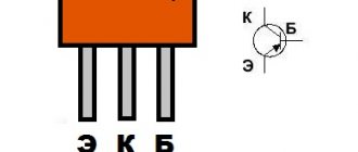
Design
Structurally, the KU202N thyristor and the entire series are made in a metal case made of coated copper alloy, which has threaded terminals and two solder terminals of varying thickness and height. The size of the threaded outlet or anode (A) is M6 for the nut. The terminals are made rigid by filling with epoxy resin, but during installation, forces should not be used more than 0.98 N.
When soldering the power terminal (K), it is necessary to maintain a minimum distance to the glass of at least 7 mm, since high temperatures may damage its integrity. When connecting the control output (CE), you should maintain a distance to the glass of at least 3.5 mm for the same reason. In this case, the total holding time of the soldering iron is not recommended to exceed more than 3 s. The effective temperature of the soldering tool tip should not exceed +260 degrees.
Design and operating principle
The stabilizer ensures constant current when it deviates.
The stabilizer ensures constant operating current of LED diodes when it deviates from the norm. It prevents overheating and burnout of LEDs, maintains constant flow during voltage surges or battery discharge.
The simplest device consists of a transformer, a rectifier bridge connected to resistors and capacitors. The action of the stabilizer is based on the following principles:
- supplying current to the transformer and changing its limiting frequency to the mains frequency - 50 Hz;
- voltage adjustment to increase and decrease with subsequent frequency equalization to 30 Hz.
The conversion process also uses high-voltage rectifiers. They determine the polarity. Stabilization of the electric current is carried out using capacitors. Resistors are used to reduce interference.
Construction and details.
The regulator is assembled in the power supply housing of the once popular “Electronics B3-36” calculator.
The triac and potentiometer are placed on a steel angle made of steel 0.5 mm thick. The corner is screwed to the body with two M2.5 screws using insulating washers.
Resistors R2, R3 and neon lamp HL1 are dressed in an insulating tube (cambric) and mounted using a hinged mounting method on other electrical elements of the structure.
To increase the reliability of fastening the plug pins, I had to solder several turns of thick copper wire onto them.
This is what the power regulators I've been using for years look like.
| to see this player. |
And this is a 4-second video that allows you to make sure that it all works. The load is a 100 Watt incandescent lamp.
Thyristor check
Many people are interested in how to check the KU202N thyristor and how to properly turn it on in the device to check its functionality. The fact is that quite often it turns out to be faulty for various reasons. Moreover, defects also occur in new products.
You can check the thyristor in several ways:
- Use a special device that analyzes the parameters of all transitions.
- Use a megger to check the condition of the main junction in both directions. In the reverse direction it should ring like a regular diode, in the forward direction it is closed, in an ideal state its resistance should be equal to infinity.
The second method is applicable only to a series of devices with the letter index M and N. In this case, you can set the dialing voltage to 400 V. Devices with the letters K and L only up to 300 V, Zh and I - up to 200 V, and so on. Before checking a product in this way, you must check its technical specifications against the reference table. Otherwise, you can damage the device without even using it for its intended purpose.
Less powerful thyristors can be tested with a conventional multimeter in continuity mode (diode and sound signal icon). In the reverse direction it rings like a diode, in the forward direction it rings infinity.
Important! When checking a thyristor in diode mode, it is necessary to combine the UE with A .
Introduction.
Many years ago, I made a similar regulator when I had to earn extra money repairing radios at a customer’s home. The regulator turned out to be so convenient that over time I made another copy, since the first sample was constantly installed as an exhaust fan speed regulator. https://oldoctober.com/
By the way, this fan is from the Know How series, as it is equipped with an air shut-off valve of my own design. Description of the design >>> The material can be useful for residents living on the top floors of high-rise buildings and who have a good sense of smell.
The power of the connected load depends on the thyristor used and its cooling conditions. If a large thyristor or triac of the KU208G type is used, then you can safely connect a load of 200... 300 Watts. When using a small thyristor, type B169D, the power will be limited to 100 Watts.
Checking in switching mode
To verify that the thyristor is working, it is enough to assemble a small switching circuit consisting of the following components:
- a light bulb or LED with a corresponding resistor, if connected to a 12V power supply;
- low voltage source, for example, AA battery;
- several conductors and a 12 V voltage source.
To carry out the check, perform the following steps:
- We connect the load to the circuit of the 12 V power source and the A-K thyristor.
- We apply negative voltage to the terminals UE and A (+ batteries must be connected to A) for an instant.
After which the light bulb or LED will light up. To make it go out, you need to turn off the switched circuit or change the polarity of the control voltage. This mode is considered normal for operation and can be used at any constant switching voltage within the permitted limits. In the case of the KU202N thyristor, it should not exceed 400 V.
Types of power regulators
Different power regulators are used for different purposes.
Thyristor control device
The design of the device is quite simple. Typically, thyristors are used in low-power devices. A thyristor thermostat consists of bipolar transistors, the thyristor itself, a capacitor and several resistors.
Thyristor transistor regulator
Transistors form a pulse signal; when the capacitor voltage is equalized with the operating voltage, they open. The electrical signal is transmitted to the output of the thyristor, after which the capacitor is discharged and the key is locked. The entire sequence of actions is repeated cyclically.
Note! The amount of delay is inversely proportional to the power supplied to the load
Triac power converter
A triac is a subtype of a thyristor, in which there are slightly more pn transitions, which is why its operating principle is somewhat different. But a triac is often considered a separate type of power stabilizer. The design consists of 2 thyristors connected in parallel and having common control.
For your information! This is where the name “triac” comes from - “symmetrical thyristors”. Sometimes it is also called TRIAC.
Diagram of 2 parallel connected thyristors (left) and triac (right)
The diagram shows that the triac has the designations T1 and T2 instead of the anode and cathode. This is because the concepts of “cathode” and “anode” in this case do not make sense, since electric current can exit through both terminals.
Triac universal regulators have a number of advantages, including low price, long service life and the absence of moving contacts, which can be sources of interference. But there are also disadvantages: susceptibility to interference and noise, lack of support for high switching frequencies.
Important! They are not used in high-power industrial installations; instead, thyristors or IGBT transistors are used.
Phase transformation method
Phase transformation occurs in so-called dimmers. Such devices are used, for example, to change the lighting intensity of halogen or incandescent lamps. The electrical circuit is usually implemented on special microcontrollers, which use their own integrated voltage reduction circuit. Due to their design, dimmers can smoothly reduce power.
LED dimmer
The disadvantages of such devices are high sensitivity to interference, high ripple factor and low signal power factor at the output. To stabilize the dimmer, dual thyristors are used.
Using modern element base
Old radio components are good because they are “oak” in terms of operational reliability. But they are already really old. For many, their time resource is at its limit and they do not last as long as “fresh” ones. This is the first problem. And secondly, they are becoming increasingly difficult to find. It’s good that there are already many soldering iron regulator circuits based on the new element base. Some of them are simple, others are more complex; various types of modern radio components are used.
Regulator circuit for a soldering iron without interference on the chip
This option cannot be called simple, but it does not emit interference into the network. With so many electronics in every home, this can be important. If you solder only occasionally, you don’t have to pay attention to it. But if you often sit with a soldering iron, interference can cause serious inconvenience.
This circuit can regulate a load of up to 2 kW and provides a smooth change from 0 to maximum.
Homemade soldering iron regulator without interference
According to the element base. The K561LA7 microcircuit can be replaced with a K176LA7. Variable resistor R1 - any of group A. The remaining resistors are better than MLT, capacitors C1, C3 are ceramic. The diodes in the circuit are KD503A; KD514A and KD522A can be replaced. There is also the option of replacing the KT361V transistor with a KT326V or KT361A.
Based on PR1500S phase power regulators
This circuit uses a phase power regulator. Apart from this, the regulator uses only a couple of parts, so assembly time is minimal and it is almost impossible to make a mistake.
DIY soldering iron tip temperature regulator
You will only need a variable resistor, maybe with a switch - then you won’t have to take the soldering iron out of the network. To eliminate interference, you will need a 100 pF capacitor, 630 V, preferably a special film one for filters. The only thing that may be difficult is winding the choke; its parameters are in the table.
Parameters for winding the choke
You will need a ferrite ring with an outer diameter of 20 mm. The greater the permeability of ferrite, the better. This phase regulator can regulate loads up to 1.5 kW, so you can choose any of their columns. You can do it with a reserve, you never know what you want to adjust later. The wire is naturally varnished copper, especially for winding chokes.
What happened after assembly
When assembling for the inductor and phase regulator, it is better to make a heat sink. It is especially useful when working with heavy loads. You can get by with a soldering iron, but you never know, connect it later and it’s better to assemble it right away with a safety margin.
On the optosimistor MOS204x/306x/308x
The circuit has been tested many times and works perfectly without any problems. It is advisable to use optical triacs of the indicated brands, since they open when the voltage crosses zero
The state of the LED does not matter. All others work on a different principle, so the circuit will need to be redone for them. The circuit also contains a 555 series bipolar timer
Finding it is not a problem, the price is normal.
Soldering iron power regulator using optosimistors
All components are selected to have miniature dimensions so that the finished board fits into the case when charging a mobile phone. The value of resistor R5 depends on the type of LED used. On red the voltage drop is 1.6-2 V, on green 1.9-4 V, on yellow 2.1-2.2 V, on blue 2.5-3.7 V. Accordingly, the resistor is selected depending on the actual parameters .
With PWM controller
The modern element base is very extensive, and the same problems can be solved in different ways. For example, use a PWM controller for a power regulator. Any model operating at a frequency of 0.5-1 Hz is suitable for this circuit. The switching element is a field-effect transistor; it can be found on old motherboards or purchased. Its type is not specified, but any n-channel transistor with a voltage of at least 12 V, a current of 6 A and a power of 60 W is suitable.
Soldering iron regulator on a PWM controller and field-effect transistor
The VD3 LED is an optional part of the circuit, but it blinks at different frequencies depending on the heating. Once you get the hang of it, it’s easy to navigate and you don’t have to look at the control knob. But in general, it can be safely thrown out of the scheme
Please note: the power buses from the microcircuit run parallel to the wires, this minimizes the influence of a more powerful load
Schematic diagram
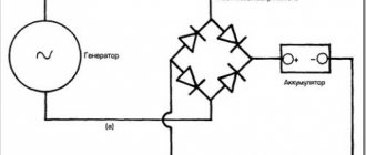
When powering powerful loads with direct current, a rectifier circuit (Fig. 1) with four power valves is often used. The alternating voltage is supplied to one diagonal of the “bridge”, the output constant (pulsating) voltage is removed from the other diagonal. One pair of diodes (VD1-VD4 or VD2-VD3) operates in each half-cycle.
This property of the rectifier “bridge” is significant: the total value of the rectified current can reach twice the maximum current value for each diode. The diode voltage limit should not be lower than the amplitude input voltage.
Since the voltage class of power valves reaches fourteen (1400 V), there are no problems with this for a household electrical network. The existing reverse voltage reserve allows the use of valves with some overheating, with small radiators (do not abuse them!).
Rice. 1. Rectifier circuit with four power valves.
Attention! Power diodes marked “B” conduct current “similarly” to D226 diodes (from the flexible lead to the body), diodes marked “VL” - from the body to the flexible lead.
The use of valves of different conductivity allows installation on just two double radiators. If you connect the “housings” of the “VL” valves (minus output) to the device body, then you will only have to isolate one radiator, on which diodes marked “B” are installed. This circuit is easy to install and set up, but difficulties arise if you have to regulate the load current.
If everything is clear with the welding process (attach the “ballast”), then huge problems arise with the starting device. After starting the engine, the huge current is unnecessary and harmful, so it is necessary to quickly turn it off, since every delay shortens the battery life (batteries often explode!).
The circuit shown in Fig. 2 is very convenient for practical implementation, in which the current control functions are performed by thyristors VS1, VS2, and power valves VD1, VD2 are included in the same rectifier bridge. Installation is made easier by the fact that each diode-thyristor pair is mounted on its own radiator. Radiators can be used standard (industrial production).
Another way is to independently manufacture radiators from copper and aluminum with a thickness of over 10 mm. To select the size of the radiators, you need to assemble a mock-up of the device and “drive” it in heavy duty. It’s not bad if after a 15-minute load the thyristor and diode housings do not “burn” your hand (turn off the voltage at this moment!).
The device body must be designed in such a way as to ensure good circulation of air heated by the device. It wouldn’t hurt to install a fan that “helps” move air from bottom to top. Fans installed in racks with computer boards or in “Soviet” gaming machines are convenient.
Rice. 2. Scheme of a current regulator using thyristors.
It is possible to implement an adjustable rectifier circuit entirely using thyristors (Fig. 3). The lower (according to the diagram) pair of thyristors VS3, VS4 is triggered by pulses from the control unit.
The pulses arrive simultaneously at the control electrodes of both thyristors. This design of the circuit is “dissonant” with the principles of reliability, but time has confirmed the operability of the circuit (“the household electrical network cannot burn” thyristors, since they can withstand a pulse current of 1600 A).
Thyristor VS1 (VS2) is connected as a diode - with a positive voltage at the anode of the thyristor, an unlocking current will be supplied through diode VD1 (or VD2) and resistor R1 (or R2) to the control electrode of the thyristor. Already at a voltage of several volts, the thyristor will open and will conduct current until the end of the half-wave of current.
The second thyristor, the anode of which had a negative voltage, will not start (this is not necessary). A current pulse comes to thyristors VS3 and VS4 from the control circuit. The value of the average current in the load depends on the opening moments of the thyristors - the earlier the opening pulse arrives, the larger part of the period the corresponding thyristor will be open.
Rice. 3. Adjustable rectifier circuits are entirely based on thyristors.
Opening thyristors VS1, VS2 through resistors somewhat “dulls” the circuit: at low input voltages, the open angle of the thyristors turns out to be small - noticeably less current flows into the load than in a circuit with diodes (Fig. 2).
Thus, this circuit is quite suitable for adjusting the welding current via the secondary and rectifying the mains voltage, where the loss of a few volts is insignificant.
The circuit shown in Fig. 4 allows you to effectively use a thyristor bridge to regulate current over a wide range of supply voltages.
The device consists of three blocks:
- power;
- phase-pulse control circuits;
- two-limit voltmeter.
Transformer T1 with a power of 20 W provides power to the control unit for thyristors VS3 and VS4 and the opening of “diodes” VS1 and VS2. Opening thyristors with an external power supply is effective at low (car) voltage in the power circuit, as well as when powering an inductive load.
Rice. 4. Thyristor bridge for current control over a wide range.
Rice. 5. Schematic diagram of the thyristor control unit.
Opening current pulses from the 5-volt windings of the transformer are supplied in antiphase to the control electrodes VS1, VS2. Diodes VD1, VD2 pass only positive half-waves of current to the control electrodes.
If the phasing of the opening pulses is “appropriate”, then the thyristor rectifier bridge will work, otherwise there will be no current in the load.
This shortcoming of the circuit can be easily eliminated: just turn the T1 power plug in the opposite direction (and mark with paint how to connect the plugs and terminals of the devices to the AC network). When using the circuit in a starter-charger, there is a noticeable increase in the supplied current compared to the circuit in Fig. 3.
Read also: DIY rollers for profile pipes video
It is very beneficial to have a low-current circuit (mains transformer T1). Breaking the current by switch S1 completely de-energizes the load. Thus, you can interrupt the starting current with a small limit switch, circuit breaker or low-current relay (by adding an automatic shutdown unit).
This is a very important point, since it is much more difficult to break high-current circuits that require good contact for the current to pass through. It is no coincidence that we remembered the phasing of transformer T1. If the current regulator were “built-in” into the charging and starting device or into the welding machine circuit, then the phasing problem would be solved at the time of setting up the main device.
Our device is specially designed to be wide-profile (just as the use of the starting device is determined by the season of the year, welding work has to be carried out irregularly). You have to control the operating mode of a powerful electric drill and power nichrome heaters.
Figure 5 shows a diagram of the thyristor control unit. The rectifier bridge VD1 supplies the circuit with a pulsating voltage from 0 to 20 V. This voltage is supplied through the diode VD2 to the capacitor C1, which provides a constant supply voltage to the powerful transistor “switch” on VT2, VT3.
The pulsating voltage is supplied through resistor R1 to resistor R2 and zener diode VD6 connected in parallel. The resistor “ties” the potential of point “A” (Fig. 6) to zero, and the zener diode limits the peaks of the pulses at the level of the stabilization threshold. Limited voltage pulses charge capacitor C2 to power the DD1 chip.
These same voltage pulses affect the input of the logic element. At a certain voltage threshold, the logic element switches. Taking into account the inversion of the signal at the output of the logic element (point “B”), the voltage pulses will be short-term - around the moment of zero input voltage.
Rice. 6. Pulse diagram.
The next logic element inverts the voltage “B”, so the voltage pulses “C” have a significantly longer duration. While the voltage pulse “C” is in effect, capacitor C3 is charged through resistors R3 and R4.
The exponentially increasing voltage at point “E”, at the moment of crossing the logical threshold, “switches” the logical element. After inversion by the second logic element, the high input voltage at point "E" corresponds to a high logic voltage at point "F".
Two different values of resistance R4 correspond to two oscillograms at point “E”:
- lower resistance R4 – greater steepness – E1;
- greater resistance R4 – lower slope – E2.
You should also pay attention to the power supply of the base of transistor VT1 with the “B” signal; when the input voltage decreases to zero, transistor VT1 opens to saturation, the collector junction of the transistor discharges capacitor C3 (preparing for charging in the next half-cycle of voltage). Thus, the logic high level appears at point "F" earlier or later, depending on the resistance of R4:
- lower resistance R4 – the pulse appears earlier – F1;
- greater resistance R4 - later an impulse appears - F2.
The amplifier on transistors VT2 and VT3 “repeats” the logical signals - point “G”. The oscillograms at this point repeat F1 and F2, but the voltage reaches 20 V.
Through isolation diodes VD4, VD5 and limiting resistors R9 R10, current pulses act on the control electrodes of thyristors VS3 VS4 (Fig. 4). One of the thyristors opens, and a rectified voltage pulse passes to the output of the block.
The smaller value of resistance R4 corresponds to the larger part of the half-cycle of the sinusoid - H1, the larger value - the smaller part of the half-cycle of the sinusoid - H2 (Fig. 4). At the end of the half-cycle, the current stops and all thyristors close.
Rice. 7. Scheme of an automatic two-limit voltmeter.
Thus, different values of resistance R4 correspond to different durations of “segments” of sinusoidal voltage on the load. The output power can be adjusted practically from 0 to 100%. The stability of the device is determined by the use of “logic” - the switching thresholds of the elements are stable.
Scheme number 2
The new circuit also has a three-pin electrical connection. component (but this is no longer a transistor) constant and variable resistors, an LED with its own limiter. Only two electrolytic capacitors have been added. Typically, typical diagrams indicate the minimum values of C1 and C2 (C1=0.1 µF and C2=1 µF) which are necessary for stable operation of the stabilizer. In practice, capacitance values range from tens to hundreds of microfarads. The containers should be located as close to the chip as possible. For large capacities, the condition C1>>C2 is required. If the capacitance of the capacitor at the output exceeds the capacitance of the capacitor at the input, then a situation arises in which the output voltage exceeds the input, which leads to damage to the stabilizer microcircuit. To exclude it, install a protective diode VD1.
This scheme has completely different possibilities. Input voltage is from 5 to 40 volts, output voltage is 1.2 - 37 volts. Yes, there is an input-output voltage drop of approximately 3.5 volts, but there are no roses without thorns. But the KR142EN12A microcircuit, called a linear adjustable voltage stabilizer, has good protection against excess load current and short-term protection against short circuits at the output. Its operating temperature is up to + 70 degrees Celsius, works with an external voltage divider. Output load current is up to 1 A during long-term operation and 1.5 A during short-term operation. The maximum permissible power when operating without a heat sink is 1 W, if the microcircuit is installed on a radiator of sufficient size (100 cm2) then P max. = 10 W.
Let's figure out how our specific thyristor power regulator works
Let us stipulate in advance that instead of the words “positive” and “negative”, “first” and “second” (half-wave) will be used.
So, when the first half-wave begins to act on our circuit, capacitors C1 and C2 begin to charge. Their charging speed is limited by potentiometer R5. this element is variable, and with its help the output voltage is set. When the voltage necessary to open dinistor VS3 appears on capacitor C1, the dinistor opens and current flows through it, with the help of which thyristor VS1 will be opened. The moment of breakdown of the dinistor is point “a” on the graph presented in the previous section of the article. When the voltage value passes through zero and the circuit is under the second half-wave, the thyristor VS1 closes, and the process is repeated again, only for the second dinistor, thyristor and capacitor. Resistors R3 and R3 serve to limit the control current, and R1 and R2 serve to thermally stabilize the circuit.
The principle of operation of the second circuit is similar, but it controls only one of the half-waves of alternating voltage. Now, knowing the principle of operation and the circuit, you can assemble or repair a thyristor power regulator with your own hands.