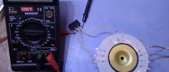
Good day to all! In the last article, I talked about determining the overall power of a RG transformer and determining the filling factor of the window kok of the transformer. This data is not enough to select a transformer. Its parameters are significantly influenced by specified quantities, for example, voltage, frequency, mode and operating conditions. Often the type of transformer, its core and windings are known initially, otherwise they should be selected based on the given conditions.
To assemble a radio-electronic device, you can pre-make a DIY KIT kit using the link.
Application of transformers
When transmitting electricity over long distances, quite large losses can occur due to heating of the wires.
To avoid such a negative phenomenon, transformers are repeatedly used. Initially, the voltage at the power plant is increased accordingly with a significant decrease in current. After the energy passes through the power lines, before delivering the current to the consumer, the voltage is reduced to an acceptable level (220 V) using transformers. Since three-phase current flows in power line networks, groups of 3 single-phase transformers connected in a star or triangular circuit are used to transform it. Three-phase transformers with a single magnetic core are also used. The equipment has high efficiency. Due to this, a large amount of heat is released. Therefore, powerful transformers are placed in containers filled with special oil.
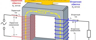
Powerful power transformer
Various electrical appliances require power supply at a certain voltage level. To do this, transformers with the required characteristics are built into their housings. High-frequency pulse transformers are used to power modern radio engineering and electronic devices.
Transformers are the basis of control and measuring devices. The point of using such devices is to safely transmit the shape of the voltage pulses of the electrical circuit under study. For example, instrument transformers are used in diesel generator systems with medium power currents (up to 1 megawatt).
Matching transformers are used when connecting devices with low resistance to electronic stages with high input or output resistance values. An example would be connecting an audio amplifier to speakers that have very low impedance.
Additional Information. The amount of energy losses in a transformer directly depends on the quality of the electrical steel core. Minimal losses due to heating, hysteresis and eddy currents occur where the cores are assembled from a large number of sections.
Application of permanent magnets
PM is of no small importance in various areas of human activity. Depending on the scope of application, PMs have different characteristics
Recently, the actively used main magnetic alloy NdFeB consists of the following chemical elements:
- “Nd” – niodium,
- "Fe" - iron,
- "B" - boron.
Areas where permanent magnets are used:
- Ecology;
- Electroplating;
- Medicine;
- Transport;
- Computer techologies;
- Household appliances;
- Electrical engineering.
Ecology
Various industrial waste treatment systems have been developed and are in operation. Magnetic systems purify liquids during the production of ammonia, methanol and other substances. Magnetic collectors “select” all iron-containing particles from the flow.
Ring-shaped PMs are installed inside gas ducts, which rid gaseous exhausts of ferromagnetic inclusions.
Separator magnetic traps actively select metal-containing waste on conveyor lines for processing industrial waste.
Electroplating
Electroplating is based on the movement of charged metal ions to opposite poles of direct current electrodes. PMs play the role of product holders in the galvanic pool. In industrial installations with galvanic processes, only magnets made of NdFeB alloy are installed.
Medicine
Recently, medical equipment manufacturers have been widely advertising instruments and devices based on permanent magnets. A constant intense field is provided by the characteristics of the NdFeB alloy.
The property of permanent magnets is used to normalize the circulatory system, extinguish inflammatory processes, restore cartilage tissue, etc.
Transport
Transport systems in production are equipped with PM installations. During the conveyor movement of raw materials, magnets remove unnecessary metallic inclusions from the array. Magnets are used to direct different products into different planes.
Note! Permanent magnets are used to separate materials where the presence of people may have a detrimental effect on their health. Automobile transport is equipped with a mass of instruments, components and devices, where PMs play the main role
These are electronic ignition, automatic windows, idle control, gasoline, diesel pumps, front panel instruments and much more.
Automobile transport is equipped with a mass of instruments, components and devices, where PMs play the main role. These are electronic ignition, automatic windows, idle control, gasoline and diesel pumps, front panel instruments and much more.
Computer techologies
All mobile devices and devices in computer technology are equipped with magnetic elements. The list includes printers, driver engines, drive motors and other devices.
Household appliances
These are mainly holders for small household items. Shelves with magnetic holders, fastenings for curtains and curtains, holders for a set of kitchen knives and a host of other household appliances.
Electrical engineering
Electrical engineering based on PM concerns such areas as radio devices, generators and electric motors.
Generators
PM generators solve the problem of moving contacts - rings with brushes. In traditional industrial devices, there are acute issues related to complex maintenance of equipment, rapid wear of parts, and significant loss of energy in excitation circuits.
The only obstacle to the creation of such generators is the problem of mounting the PM on a rotating rotor. Recently, magnets have been placed in the longitudinal grooves of the rotor, filled with low-melting material.
Generator rotor and stator
Electric motors
In household appliances and in some industrial equipment, synchronous electric motors with permanent magnets have become widespread - these are DC valve motors.
As in the generators described above, the PM is installed on rotors rotating inside stators with a stationary winding. The main advantage of the electric motor is the absence of short-lived conductive contacts on the rotor commutator.
Permanent magnet motor
Engines of this type are low-power devices. However, this does not in any way diminish their usefulness in the field of electrical engineering.
The author hopes that after reading this article the reader will have a clear idea of what a permanent magnet is. The active introduction of permanent magnets into human activity stimulates the invention and creation of new ferromagnetic alloys with enhanced magnetic characteristics.
Advantages of using electromagnets
The main advantage of an electric magnet over a constant source of magnetic field is that it is brought into working condition under the influence of electric current. That is, when it is necessary to exert a magnetic influence on a certain part of space, the current is turned on. This allows for rhythmic operation of the EM, which is successfully used in various types of electrical equipment, instruments and devices.
An electromagnet can be found in electric meters, separator units, transformers, television and audio equipment and other devices.
Powerful magnets are installed on overhead cranes in the workshops of metallurgical plants and winches of scrap metal collection enterprises.
Lifting electromagnets
One of the first applications of EMs is as speakers. The sound device is based on an electromagnet, which causes the membrane to vibrate in the audio range.
EMs are used in metal detectors to detect metal-containing objects underground, in water and in various areas.
Major producers of electrical steel
If we consider the production of this type of metal on a global scale, the main players are the eastern countries: China and Japan. Their share in the production and consumption of electrical steel is up to 50%. The imbalance between the countries is that China is the main producer, while Japan predominantly exports this range of steel.
Finished products – electrical steel coils
Russia is one of those countries where metal production volumes exceed domestic consumption of the electrical steel range. The price of this type of product on the domestic market ranges from 80 to 180 rubles per kilogram. Today, the Russian Federation has managed to reach production volumes of this range of metal, which amount to 10% of the total global import of electrical steel. The main metal producers on the Russian market are:
- Severstal;
- VIZ-Steel;
- Novolipetsk Metallurgical Plant.
The volumes of products they produce are three times greater than the needs of the domestic market, which allows them to import electrical steel both to the West: Italy, Switzerland, and to the East - India. As for the share of a specific type of steel in the total volume, two-thirds of the production capacity is focused on the production of a dynamic range of metal. And only 30% of production is transformer steel, the price of which is 120 - 180 rubles / kg.
Source
Hysteresis loop
Hysteresis in Greek means delay. The graphical representation of the hysteresis loop reflects the degree of magnetization of a body located in an external magnetic field. Hysteresis is the dependence of magnetization vectors and magnetic field strength in any medium on the applied external MF. The state of the body at a given time is compared with its previous state. In this case, there is a lag in the body’s reaction to the influence of external MF. The physical effect is clearly manifested in ferromagnets: iron, cobalt, nickel and their alloys. The hysteresis loop provides an explanation for the existence of permanent magnets.
Hysteresis loop
Note! Magnetic hysteresis of a ferromagnet is the lag between changes in the degree of magnetization of a body and changes in the external magnetic field. That is, the loop shows the dependence of the degree of magnetization on the sample’s history
The magnetic permeability of a ferromagnet is a variable value; it is closely related to the induction of an external field. The magnetization curve of the core is a curved loop, at a certain degree of saturation of the ferromagnetic field. In the future, this value does not increase. If the external induction is reduced to zero, the ferromagnet will retain residual magnetization. When the direction of the external field changes, the ferromagnet is remagnetized in the opposite direction.
Instrument transformers
In this class there are two types of devices that provide transformations for measuring network parameters:
Instrument transformers are created with a high class of accuracy. During operation, their metrological characteristics are periodically checked for the correctness of measurement of both the magnitudes and deviation angles of the current and voltage vectors.
Current transformers
The main feature of their device is that they are constantly operated in short circuit mode. Their secondary winding is completely short-circuited to a small resistance, and the rest of the structure is adapted for such work.
To eliminate emergency mode, the input power is limited by a special device in the primary winding: only one turn is created in it, which cannot create a large voltage drop across the winding when current flows through it and, accordingly, transmit high power to the magnetic circuit.
This turn cuts directly into the power circuit, ensuring its serial connection. For individual designs, a through hole is simply created in the core, through which a wire with primary current is passed.
The load of the secondary circuits of a current transformer under voltage must not be interrupted. For this reason, all wires and connecting terminals are manufactured with increased mechanical strength. Otherwise, high-voltage voltage immediately appears at the broken ends, which can damage the secondary circuits.
Thanks to the operation of current transformers, it is possible to provide constant monitoring and analysis of loads flowing in the electrical system. This is especially true for high-voltage equipment.
Instrument current transformers 110 kV
The rated values of secondary currents of energy instrument transformers are 5 amperes for equipment up to 110 kV inclusive and 1 A - higher.
Current transformers are widely used in measuring instruments. Due to the use of a sliding magnetic circuit design, it is possible to quickly perform various measurements without breaking the electrical circuit, which must be done when using conventional ammeters.
Current clamps with a sliding magnetic core of a current transformer allow you to grasp any conductor with voltage and measure the magnitude and angle of the current vector.
Voltage transformers
A distinctive feature of these designs is that they operate in a mode close to the idle state, when the value of their output load is low. They are connected to the voltage system whose value will be measured.
Voltage transformer 110 kV
Voltage measuring transformers provide galvanic isolation of equipment from primary and secondary circuits and operate in each phase of high-voltage equipment.
From them, entire complexes of measurement systems are created that make it possible to filter and isolate various components of voltage vectors, the accounting of which is necessary for the accurate operation of protections, interlocks, and alarm systems.
Due to the operation of current and voltage transformers, vectors of secondary quantities proportional to the primary quantities are removed in real time. This allows not only to create measurement and protection circuits for current and voltage, but also, through mathematical transformations of vectors, to analyze the state of powers and resistances in the existing electrical system.
Transformer steel composition
The material is made not only from silicon, but also an alloy with iron. The addition of this element causes the force coefficient to increase and the electrical power resistivity to increase when compared to grades without silicon.
If you add a certain amount of silicon to the composition, this will lead to a decrease in the individual weight of iron oxides.
According to the chemical composition, this material can be classified as an alloy metal due to the presence of silicon in an amount of up to 0.5%.
Methods for assembling a magnetic system
Butt magnetic system
In this design, the yoke and rods are connected into a system after the windings are installed. This type of apparatus is assembled in two ways, depending on the design:
- in devices in which the magnetic circuit is made of strips of electrical steel, it consists of 4 (in three-phase, from C-shaped parts, they are connected to each other using a steel case;
- in devices in which the magnetic circuit parts are made of rings consisting of a single strip, all parts are connected using electric welding.
The advantage of this connection is ease of assembly, but the disadvantage is increased resistance to magnetic flux and increased eddy current losses.
Laminated magnetic cores
In laminated magnetic cores, its design consists of individual rectangular and (or) W-shaped plates. These plates are intertwined (laminated) in the coils of the electric transformer after winding the windings.
A magnetic system with a laminated connection method is more labor-intensive during assembly, but has fewer losses during operation.
The yoke is one of the components of an electrical transformer, no less important than other elements. Therefore, to design devices, it is necessary to know what a yoke is and what function it performs in a transformer.
Main dimensions of the transformer
The geometric dimensions of the transformer in most cases are decisive for its technical and economic indicators. The main dimensions of a transformer coil are its height and width (thickness), limited by the dimensions of the core. For the core, the main dimensions will be: the width of the rod carrying the coil a ; rod thickness b ; window width c and window height h .
Main dimensions of transformer cores of different types.
In core specifications and literature, the unit of measurement for dimensions is usually millimeters mm ( mm ).
To simplify calculations and some unification of cores, the so-called basic size was introduced in domestic literature and calculation methods. One of the main transformer sizes can be taken as the base one. In most cases, the width of the rod a is taken as the base size. Then the geometry of the core is described by the following relations
Using the base size a and dimensionless coefficients x, y, z, you can express all the geometric characteristics of the transformer: lengths, sections, surfaces and volumes. For example, core cross-section Sc = ab, and taking into account the base size Sc = ya2. Volume of armored transformer BT
and taking into account the base size
that is, the geometric parameters of the transformer, taking into account the basic size, are expressed by formulas like
where k – can have a value from 1 to 3, depending on the type of quantity (1 – length; 2 – area, surface, section; 3 – volume);
φi is a function of the geometric characteristic of the transformer, the index “i” indicates a specific characteristic.
| Transformer characteristics | Function designation | Characteristic designation |
| Average magnetic line length | φl | lc= φla |
| Average length of coil turn | φw | lw=φwa |
| Core cross section (geometric) | φs | sc= φsa2 |
| Total cross-section (area) of the core window | φok | sok= φoka2 |
| Coil cooling surface area | φpk | Pk= φpka2 |
| Core cooling surface area | φps | Ps= φpsa2 |
| Volume occupied by the coil | φk | Vk= φka3 |
| Volume occupied by the core | φс | Vс= φсa3 |
Geometric characteristics of the transformer and their functions.
Geometry functions are dimensionless, making it easier to analyze different types of transformers.
Electromagnets and their applications
Here are some of the examples where they are used:
- Motors and generators. Thanks to electromagnets, it has become possible to produce electric motors and generators that operate on the principle of electromagnetic induction. This phenomenon was discovered by scientist Michael Faraday. He proved that electric current creates a magnetic field. The generator uses the external force of wind, moving water or steam to rotate a shaft, which causes a set of magnets to move around a coiled wire to create an electric current. Thus, electromagnets convert other types of energy into electrical energy.
- Industrial use practice. Only materials made from iron, nickel, cobalt or their alloys, as well as some natural minerals, react to a magnetic field. Where are electromagnets used? One of the areas of practical application is metal sorting. Since the mentioned elements are used in production, iron-containing alloys are effectively sorted using an electromagnet.
- Where are electromagnets used? They can also be used to lift and move massive objects, such as cars before disposal. They are also used in transportation. Trains in Asia and Europe use electromagnets to transport cars. This helps them move at phenomenal speeds.
Main brands
There are two main brands.
Sulphurous
Brand 2212. For industrial production, thin sheets subject to cold rolling are used.
Unalloyed
It differs from carbon steel in that it contains less than 5% alloying elements.
Both types are used in the production of transformer steel.
Magnetic core and its purpose?
With the help of a magnetic circuit, voltage is converted with a reduction in losses. Special ferromagnetic steel is used in the production of cores.
What types of transformer cores are there?
The types of cores are:
- core;
- armored;
- toroidal.
The rod cores are made in the shape of the letter P. The windings are on the rods, and the rods are connected using a yoke. Magnetic cores of this design are easy to inspect. And the windings are available for repair. As a rule, medium-power and high-power transformers are produced with such cores.
Armor cores are made in the shape of the letter W. The windings are wound on the central part of the core. Armor transformers are more complex to manufacture. And the windings in such a transformer are more difficult to repair than in a rod transformer.
Toroidal cores are made in the shape of a ring. The windings are wound directly onto the magnetic core. It is believed that the most minimal losses occur in such cores.
a – diagram of a rod core, b – diagram of an armored core, c – diagram of a toroidal core.
How to reduce losses in a transformer core?
When the load is on, the transformer core is exposed to an alternating magnetic field. It provokes the occurrence of eddy currents outside the core. They are spent on heating the magnetic circuit - that is, this energy does not go into the useful power of the equipment.
Losses due to magnetization reversal depend on:
- properties of the magnetic circuit material. The easier it is to magnetize a metal, the easier it is to remagnetize. Accordingly, the losses due to magnetization reversal in this case will be less;
- magnetization reversal frequencies;
- maximum value of magnetic induction.
To reduce losses, transformer cores are made of metal with pronounced magnetic properties. Such a core is much easier to remagnetize.
The next point is the solidity of the core. A solid magnetic circuit has low resistance, so the current in them reaches a maximum. To offset this, manufacturers increase the core resistance. To do this, it is assembled from separate plates, which are isolated from each other.
The core is formed in different ways:
- end-to-end - first the core is assembled, then the windings are wound and the structure is secured with a yoke;
- interlacing (by blending) - in this case, each new row overlaps the joints on the previous row.
Types of magnetic cores
Magnetic cores are made of rod, armor and ring structures.
Rod type
Vertical cores of stepped cross-section form a circle with horizontal yokes. The windings are located only on the vertical elements. The entire magnetic circuit system is arranged in the form of a closed circuit.
Lamellar magnetic cores
Armor type
The cores have a rectangular cross-section. They occupy a horizontal position. The windings are also made in a rectangular shape. In order to implement such an equipment configuration, a rather complex production technology is required. Therefore, this type of MP is used only in special types of transformers.
Ring – toroidal type
Ring tape magnetic cores are used in the assembly of single-phase power transformers. MPs are made from cold-rolled electrical steel with a thickness of 0.08, 0.3 and 0.35 mm. Toroidal cores are made of ferrite or carbonyl iron. They are widely used in radio electronics.
Ring toroidal MPs
Characteristics and principle of operation
The principle of operation of the MF is to increase the magnetic field directed to the secondary winding of the electrical device. The characterizing values of MF directly depend on the composition of the alloy used for the manufacture of cores. Ferromagnets are considered the most effective amplifiers.
In order for the magnetic flux strength in the core to constantly increase, it is necessary to increase the current strength and the number of turns in the coil.
You should understand! The magnitude of the magnetic field is limited by the characteristics of the material from which the core is made.
To clearly express the characteristics of the magnetic circuit, they are displayed graphically on coordinate axes. The change in values looks like a closed curved line called a hysteresis loop.
Why is a magnetic circuit needed?
To understand what a magnetic circuit is, we need to consider the structure of a simple transformer. Two induction coils are wound on cores combined into a single structure. They are the magnetic circuits (MC).
Hysteresis loop
The energized primary coil induces a magnetic field into the core, which induces magnetic flux into the secondary winding. As a result, the MF induces a current in the second coil, but with different characteristics.
Important! The cores are made of special transformer steel - ferrites. It is an alloy of iron with oxides of other metals.
Magnetism and electricity
The dictionary definitions of electricity and magnetism are different, although they are manifestations of the same force. When electric charges move, they create a magnetic field. Its change, in turn, leads to the generation of electric current.
Inventors use electromagnetic forces to create electric motors, generators, MRI machines, levitating toys, consumer electronics and many other invaluable devices without which it is impossible to imagine the daily life of a modern person. Electromagnets are inextricably linked with electricity; they simply cannot work without an external power source.
Why is silicon in steel?
Alloying is carried out not with the pure element silicon, but with ferrosilicon. This substance is an alloy of FeSi with iron. Alloying steel with Si allows oxygen to be removed from the metal, an element that has the greatest negative effect on the magnetic properties of Fe. A reaction occurs in the reduction of iron from its oxides, with the resulting formation of silicon oxide, which partially turns into slag.
This is what ferrosilicon looks like - grade FS45
The second positive effect of the introduction of silicon into steel is associated with the release of cementite (Fe3C) from the metal, which is replaced by the resulting graphite. Both compounds, iron oxide and cementite, increase the coercive force in the metal, which leads to an increase in hysteresis losses. Moreover, silicon alloying of iron with a Si concentration above 4% also helps to reduce eddy current losses, which is due to an increase in the electrical resistivity of electrical steel relative to its grades not alloyed with silicon.
Superconducting electromagnet
Superconductivity is considered the property of materials with resistance close to zero. Electromagnets with practically zero resistance have a super-powerful magnetic field. The force of magnetic influence can cause diamagnetic materials such as pieces of lead and organic objects to float in space.
As physicists have noticed, metals acquire the property of superconductivity at ultra-low temperatures. To obtain the superconductivity effect, the EM windings are placed in a Dewar flask with liquid helium, which is equipped with a valve to release the vapor of the substance. Superconducting magnets are used in medical equipment - MRI (magnetic resonance tomography) machines. Experimental hovercraft trains use superconducting magnets.
Superconducting magnet
Design features
The greatest inductance is obtained when the core is short-circuited. Such a magnetic circuit can be toroidal if it has the shape of a donut (toroid). They are used to obtain a minimum leakage inductance, that is, a magnetic field located outside the magnetic circuit. But since they are difficult to manufacture, magnetic cores are more often used from two mirror-symmetrical parts inserted inside a cylindrical coil, which is easy to manufacture.
In the material of the magnetic circuit, one can conditionally distinguish many short-circuited windings. Alternating current in the winding causes loss currents in them. To reduce losses, it is made multi-layered with reliable insulation of the layers from each other. Typically, plates of the required shape are used for this. Most of the transformers and chokes used in centralized power supply networks are made from them. Less commonly used is a design in the form of a tape in a roll. It is more difficult to dock with other parts of the magnetic circuit, if any.
Structurally, the cores are either rod or armored. They are widely used in transformers and chokes as shown in the images below:
Metal cores made of iron-based alloys are used in all electrical machines operating at a voltage of 50 Hz. The image shows the magnetic circuit of an electric motor. The grooves are designed to accommodate the winding turns.
Increasing the frequency significantly reduces the weight and dimensions of the cores. A very clear example of this are base fluorescent lamps. But in high-frequency devices it is necessary to use other materials for the manufacture of magnetic cores. Even the thinnest iron-based alloy plates become unacceptably hot at high frequencies.
With an increase in frequency above 50 Hz, nickel-based permalloy alloy is used for cores, and at frequencies above 1 kHz, sintered powder cores are used. Permalloy cores are structurally the same as those made from iron - rod and armor, only smaller in size with equal powers of transformers and electric motors. But powder cores are very diverse in their composition. They are small in size and easy to manufacture not only for rod and armor structures, but also for cups, as can be seen in the image on the left.
These cores are used in switching power supplies, electronic ballasts for fluorescent lamps and in various electronic devices in oscillating circuits, transformers and filters. Various grades of ferrites are most widely used as core material.
In short, modern materials make it possible to produce magnetic circuits to solve most technical problems.
Transformer production technology and equipment - Active steel of magnetic cores
Page 7 of 92
CHAPTER FIVE APPLICATION OF ELECTRICAL STEEL IN THE PRODUCTION OF TRANSFORMERS
1. ACTIVE STEEL MAGNETIC CORE
The magnetic system (magnetic core) has a magnetic resistance that depends on the length of the circuit, its cross-section and the properties of the material from which it is assembled—its magnetic permeability. In order to reduce the magnetizing current for a given magnetic flux, and therefore a given flux density per unit cross-section (magnetic induction), it is necessary to make the magnetic resistance of the active part of the magnetic circuit as small as possible, therefore, it is necessary to make it from a material with high permeability. Such a material is electrical steel, which has a magnetic permeability several orders of magnitude greater than air.
More than 60 years ago, electrical steel sheets alloyed with 1 - 4% silicon were produced. Currently, high-alloy hot-rolled electrical steels have a silicon content of 3.8–4.8%. In 1935, the so-called cold-rolled electrical steel was produced by cold rolling of silicon steel [L. 8]. The advantages of cold-rolled steel over hot-rolled steel are so significant that at present almost only cold-rolled steel is used in transformer construction. The best samples of this steel have specific losses p10/50 for sheets 0.35 mm thick and less than 0.5 W/kg. Reducing specific losses made it possible to increase the induction in the magnetic circuit to 1.6-1.7 T versus 1.4-1.5 T for hot-rolled steel. This made it possible to significantly reduce the size of the magnetic cores. In the transformer industry, the following grades of electrical steel were used according to GOST 802-58: a) hot-rolled electrical steel grades E22, E41, E42, E43, E43A; b) cold-rolled textured electrical steel grades E310, E320, E330 and E33O-A, E33O-AP. The best grades of cold-rolled steel - E33O, E33O-A and E33O-AP - were predominantly used. The alphabetic and numerical designations of the steel grade conventionally indicate: E - electrical steel; the first digit is the degree of alloying of steel with silicon in percentage: 1 - lightly alloyed (0.8-1.8% silicon); 2 - medium doped (1.8-2.8% silicon); 3 - highly doped (2.8-3.8% silicon); 4 - highly alloyed (3.8-4.8% silicon); the second digit is the level of specific losses: 1 - normal specific losses; 2 - reduced specific losses; 3 – low specific losses; the third digit (0) indicates that the steel is cold-rolled, textured; the letter A indicates particularly low losses of electrical steel, the letter P indicates increased precision in rolling and finishing. Electrical steel is produced both in sheets and in rolls. Sheet sizes: 150X1500, 1000X2000, 600x1500 and 860X1720 mm. Roll dimensions: width 800 and 950 mm, diameter 500 mm. The thickness of the produced electrical steel is 0.5 and 0.35 mm. Tolerances on the thickness of sheets of normal rolling accuracy are 0.5 ± 0.05 and 0.35 ± 0.04 mm for hot-rolled steel; for cold rolled steel 0.5±0.04 and 0.35±0.03 mm. Tolerances on the thickness of coiled steel are ±0.03 mm. On the surface of electrical steel, significant pockmarking, defects in edges and corners, warping1 with a box height of more than 2-4 mm per 1 m and waviness *, ** with a wave height of more than 4-6 mm per 1 m are not allowed; the wavelength or box must be less than 25 times its height.
* Cupping is a deformation of the sheet in the form of a box with bent ends of the sheet.
**Waviness is the deformation of the steel strip over its entire width and with a uniform wave pitch. The wave is visible from the end (thickness) of the steel strip.
In table Table 5-1 shows the electromagnetic characteristics of various steel grades in accordance with GOST 802-58: values of magnetic induction, specific losses at a frequency of 50 Hz and specific electrical resistance. In connection with the widespread use of cold-rolled textured steel in transformer manufacturing, we will consider some of its characteristics [L. 8]. Cold-rolled steel has special magnetic properties when, as a result of rolling and heat treatment, individual crystals are oriented, forming axes of predominant magnetization in the direction of sheet rolling and, conversely, difficult magnetization in the transverse direction. Thus, steel, which, according to the structure of the crystallographic lattice, has crystals oriented in a certain direction, is called textured. A distinction is made between steel with an edge texture, when the crystals are oriented along the rolled edge of the cube, and steel with a cubic texture, when the crystals are oriented along the side of the cube. Electrical steel with a ribbed texture has pronounced anisotropy, i.e., the dissimilarity of all or some physical properties in different directions. Such a structure provides the least resistance to magnetic flux only along the rolling direction and increased resistance to magnetic flux across or at some other angle to the rolling direction. Steel with a cubic texture has equally high magnetic properties both along and across the rolling, but this steel is not yet produced on an industrial scale.
Table 5-1
| steel grade | Sheet thickness, mm | Magnetic induction, T (104 gf), at magnetic field strength, A/cm | Specific losses, W/kg | Average electrical resistivity of steel, Ohm-mm2/m | ||||||
| B10| | B25 | B50 | B100 | At 200 | P10 | P15 | P17 | |||
| no less | no more | |||||||||
| E41 | 0,50 | 1,30 | 1,46 | 1,57 | 1,70 | 1,90 | 1,55 | 3,50 | 0,6 | |
| E42 | 0,50 | 1,29 | 1,45 | 1,56 | 1,69 | 1,80 | 1,40 | 3,10 | — | 0,6 |
| E43 | 0,50 | 1,29 | 1,44 | 1,55 | 1,69 | 1,89 | 1,25 | 2,90 | — | 0,6 |
| E43A | 0,50 | 1,29 | 1,44 | 1,55 | 1,69 | 1,89 | 1,15 | 2,70 | — | 0,6 |
| E41 | 0,35 | 1,30 | 1,46 | 1,57 | 1,70 | 1,90 | 1,35 | 3,00 | — | 0,6 |
| E42 | 0,35 | 1,29 | 1,45 | 1,56 | 1,69 | 1,89 | 4,20 | 2,80 | — | 0,6 |
| E43 | 0,35 | 1,29 | 1,44 | 1,55 | 1,69 | 1,89 | 1,05 | 2,50 | — | 0,6 |
| E43A | 0,35 | 1,29 | 1,44 | 1,55 | 1,69 | 1,89 | 0,90 | 2,20 | — | 0,6 |
| E310 | 0,50 | 1,60 | 1,75 | 1,83 | 1,91 | 1,98 | 1,10 | 2,45 | 3,2 | 0,5 |
| E320 | 0,50 | 1,65 | 1,80 | 1,87 | 1,92 | 2,00 | 0,95 | 2,10 | 2,8 | 0,5 |
| E330 | 0,50 | 1,70 | 1,85 | 1,90 | 1,95 | 2,00 | 0,80 | 1,75 | 2,5 | 0,5 |
| E310 | 0,35 | 1,60 | 1,75 | 1,83 | 1,91 | 1,98 | 0,80 | 1,75 | 2,5 | 0,5 |
| E320 | 0,35 | 1,65 | 1,80 | 1,87 | 1,92 | 2,00 | 0,70 | 1,50 | 2,5 | 0,5 |
| E330 | 0,35 | 1,70 | 1,85 | 1,90 | 1,95 | 2,00 | 0,60 | 1,30 | 1,9 | 0,5 |
| E330 A | 0,35 | 1,70 | 1,85 | 1,90 | 1,95 | 2,00 | 0,50 | 1,10 | 1,6 | 0,5 |
Hot-rolled steel has a weak crystallographic texture, so the values of magnetic permeability in different directions of the sheet differ slightly. The less cold-rolled steel contains carbon, sulfur and gas, the better its magnetic properties. With a decrease in the content of crystalline inclusions, the ductility of steel noticeably increases. This makes it possible to increase the silicon content in steel, which further reduces losses. It has been established that the main properties of electrical steel are determined by the presence of oxygen, carbon and nitrogen in it. Therefore, in the production of electrical steel, it is necessary to ensure the production of liquid steel containing no more than 0.01 - 0.08% carbon, 0.003% oxygen and 0.004% nitrogen. Of exceptional importance for the quality of cold-rolled steel is high-temperature annealing in vacuum furnaces at metallurgical plants and vacuum processing of liquid metal. When working with cold-rolled steel, the technology for producing magnetic cores is of particular importance. Cutting, stamping, heat treatment and assembly of positions are very important for obtaining the specified characteristics of the transformer (losses and no-load current, noise level, vibration, efficiency, etc.). When cutting cold-rolled steel, you should strictly ensure that the direction of the magnetic flux along its entire length coincides with the direction of steel rolling, since deviation of the flow from the rolling direction leads to an increase in losses and no-load current. The presence of holes in the rods and yokes of magnetic circuits causes a decrease in the cross-section and deviation of the magnetic flux from the rolling direction, and consequently leads to an increase in losses and a decrease in magnetic permeability. Particularly large losses occur at the transition points from the rod to the yoke, which is why magnetic cores are made with an “oblique joint”, multi-frame, etc. Cold-rolled steel is very sensitive to all kinds of mechanical influences. When cutting and stamping plates, the magnetic properties of steel deteriorate due to the formation of hardening in the cut zone. Hardening leads to an increase in resistance to magnetic flux and an increase in specific losses of steel. Impacts on steel, bending of plates, etc. easily disrupt the orientation of crystals in grain-oriented steel; at the same time, the specific losses and specific magnetizing power in steel increase significantly. Restoring the magnetic characteristics of electrical steel is achieved by annealing it, which will be discussed below. Rolled electrical steel with a heat-resistant insulating coating in the form of oxide films has become widespread in the domestic transformer industry. The use of coiled steel makes it possible to widely introduce automation in the production of magnetic core plates on semi-automatic and automatic longitudinal and transverse cutting lines, and also to abandon in some cases additional insulation of the plates. The specific losses in the active steel of the manufactured magnetic core are, as a rule, slightly higher than those of the original material, and are characterized by a loss increase factor. The loss increase factor is the ratio of the specific losses in the manufactured magnetic circuit to the specific losses of the source material, determined on samples in the Epstein apparatus. Rice. 5-1. Scheme of a varnishing machine. 1 — magnetic circuit plate; 2 — rubber rollers; 3—tube with holes; 4 — supply tank with varnish; 5 - underground tank with varnish; 6 - pump; 7 - cold conveyor; 8 - hot conveyor; 9 — gas burners; 10 - oven; 11, exhaust ventilation; 13 - cold conveyor; 14 — supply ventilation; 15 reception table, 16 - self-propelled trolley; 17 — rubber rollers (for squeezing water); 18 - water nozzle.
This coefficient is the most important indicator of the design and technological level of production of magnetic cores and transformers in general. The task of modern transformer manufacturing is to achieve a minimum value of this coefficient. For domestically produced magnetic cores, the loss increase factor is 1.2–1.5.
- Back
- Forward
Operating principle
To understand how electromagnets work, we need to look at their design. A simple device explains the principle of operation of an electromagnet. When an electric charge flows through the body of the winding, magnetic field radiation occurs, penetrating the magnetic circuit.
Inside a metal or ferromagnet, in accordance with the laws of physics, microscopic magnetic fields called domains are formed. Their fields, under the external influence of the winding, are arranged in a certain order. As a result, the magnetic forces of the domains are summed up, forming a strong magnetic field, giving the magnetic circuit the ability to attract massive metal objects.
Important! To stop electromagnetic induction, it is enough to disconnect the EM from the current source. In this case, a particle of the magnetic field will remain
This effect is called hysteresis.
Magnetic field amplifier
If there is a need to strengthen it, magnetic circuits are used. They are also called cores. Their material and design depend on the purpose of the device
The core material is its most important component. The properties of the material mainly determine the processes that occur in the core
These processes are different in the case of its interaction with direct and alternating current.
The simplest magnetic circuit is a rod with a round or other shaped cross-section. It is covered by the turns of a coil, which in some devices is called a winding. Various materials have magnetic properties. The most effective electromagnetic field amplifiers are materials called ferromagnets. These are iron-based alloys with the addition of some other components. Additives are determined by the properties of the alloy that are sought to be obtained as a result.
If you make a monolithic cylinder from such an alloy and place it inside a coil, you will get a device that can be used for various purposes. If the current in the winding is constant, such a device will create a constant magnetic field. The result is an electromagnet. In order for the magnetic field strength in the core to increase, it is necessary to increase either the current strength in the winding, or the number of turns in the winding, or both.
But the increase in magnetic field strength in the core is limited by the properties of the alloy. This effect is called magnetic hysteresis, and the state of the magnetic circuit is called saturation. Graphically, the processes in the magnetic circuit are displayed in the form of a hysteresis loop:
Saturation of the magnetic circuit begins near the horizontal section of the curve when moving along it from zero.
Any coil has inductance. The core significantly increases this inductance. Therefore, such coils are used in alternating current circuits and are called chokes. Inductance is determined primarily by the mass of the core. The distance between its ends is the next parameter that affects the amount of inductance and is called the gap.
Electrical steel – grades
The marking of a given type of metal represents a number, where its digits indicate:
- The first is the structural state of the metal and its rolling class. This can be hot-rolled (1) or cold-rolled (2) isotropic, as well as cold-rolled anisotropic steel.
- The second one displays the percentage of silicon present. It takes the following permissible values from 0 to 5. The starting value - less than 0.4% is designated as 0. The second digit 1 corresponds to the Si 4 content - 0.8%. The next four values represent an increase in silicon concentration by 1, up to a value of 4.8%.
- The third number characterizes electromagnetic characteristics: coercive force, magnetic induction and others.
- The last two digits display the quantitative value of the characteristic from the third point.
Special types of transformers
This group includes:
Isolation transformers
Placing two windings of exactly the same design on a common magnetic circuit allows us to obtain the same output voltage from 220 volts 50 hertz at the input.
This begs the question: why make such a transformation? The answer is simple: to ensure electrical safety.
When the insulating layer of the wire of the primary circuit breaks down, a dangerous potential appears on the body of the device, which, through a randomly formed circuit through the ground, can shock a person and cause him electrical injury.
Galvanic separation of the circuit allows optimal use of power to electrical equipment and at the same time eliminates injury from breakdowns of insulation of the secondary circuit on the housing.
Therefore, isolation transformers are widely used where working with power tools requires additional safety measures. They are also widely used in medical equipment that allows direct contact with the human body.
High frequency transformers
They differ from conventional ones in the material of the magnetic core, which, unlike conventional transformer iron, is capable of transmitting high-frequency signals well, without distortion.
Used in electrothermal applications, in particular for induction heating in electrothermal installations for high-frequency metal welding, melting, soldering, hardening, etc.
Matching transformers
The main purpose is to match the resistances of different parts in electronic circuits. Matching transformers are widely used in antenna devices and amplifier designs based on audio frequency vacuum tubes.
Welding transformers
The primary winding is created with a large number of turns, allowing it to normally handle electrical energy with an input voltage of 220 or 380 volts. In the secondary winding, the number of turns is much smaller, and the current flowing through them is high. It can reach thousands of amperes.
Therefore, the thickness of the wire of this circuit is chosen to have a larger cross-section. There are many different ways to control the welding current.
Welding transformers are widely used in industrial installations and are popular among those who like to make various homemade products with their own hands.
The types of transformers considered are the most common. Other similar devices that perform special tasks in technological processes also operate in electrical circuits.
Types of transformer magnetic cores
There are butt designs and laminated designs of core magnetic cores. They differ in the type of connection of the main element with the yoke.
Butt design
In this design, the assembly of yokes and rods is carried out separately. First, a winding is mounted on the rod, after which the upper yoke is attached. To insulate the plates, electrical cardboard is placed between the joining elements. After installing the yoke, the structure is pressed and tightened using vertical pins. This type of assembly is used for shunt and current-limiting reactors. This depends mainly on the dimensions of the installation. With small dimensions of the final product, this assembly is very convenient, since you only need to remove the upper yoke to install the windings.
When it comes to using such a design in power transformers, there is a need for bulky devices to tie the product. The surfaces of the rods and yokes to be joined must be mechanically processed. This reduces magnetic resistance, but requires large material costs and time. Therefore, another type of assembly is used for power transformers - fusion.