Plasma cutting machines help to form workpieces of any configuration. They are able to work with all metals and are used in many industries. The devices are also used at home. Since many workshops have welding units, you can make plasma cutters with your own hands from basic machines.
Appearance
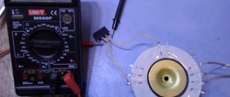
The plasma cutting installation consists of the following parts:
- a plasma cutter or plasma torch that creates a plasma flow;
- welding transformer feeding the plasma torch;
- an oscillator or arc ignition unit that supplies high voltage at the moment the cut begins to form a plasma flow;
- a compressor to create air flow through the plasmatron;
- cables connecting the welding machine, plasma torch and the part being cut;
- hoses through which air or other gas and, if necessary, coolant are supplied.
The plasma head looks like a torch for a semi-automatic welding machine. Cables and hoses are also connected to it, but instead of a wire, a stream of plasma heated to 8000°C comes out of the nozzle.
Typical plasma cutter design
A standard plasma cutter includes the following components:
- Power unit. Used to supply current to the rod.
- Plasmatron. An important part of the apparatus, which has a complex structure. In this block, under the influence of current, a powerful plasma jet is formed.
- Oscillator. Used to quickly ignite the arc and maintain it.
- Compressor. Creates a powerful air stream entering the burner. This helps to cool the plasma torch, heat the plasma, and automatically remove the melt from the cutting site.
- Cable hose. Through this element, current is supplied to the burner. This promotes gas ionization and initiation of an electric arc. In addition, air enters under pressure through the tube.
- Ground wire.
How the device works
A plasma cutting installation is a kind of hybrid of electric welding and a gas cutter - the metal is melted by electricity, and the melt is blown out by a gas stream.
The main part of this device is the plasmatron. Inside it is a copper electrode with a rod made of a refractory metal - beryllium, thorium, zirconium or hafnium. At the end of the head there is a nozzle that forms a plasma flow. The nozzle is separated from the electrode by an insulator. The cut is made with reverse polarity - the electrode is the anode, and the nozzle and the metal being cut are the cathode.
The installation works as follows:
- when the unit is turned on, voltage from the welding transformer is supplied to the electrode and nozzle;
- with the help of an oscillator, an auxiliary electric arc occurs between these elements, limited by additional resistance;
- this arc heats the gas supplied to the plasmatron to 8000°C, which turns it into plasma and increases the pressure inside the head;
- a stream of air or other gas blows the plasma stream out of the nozzle;
- when leaving it, the plasma is compressed into a narrow beam, the speed of which can reach 1500 m/s, and the temperature 30000 ° C;
- when the plasma and the part being cut come into contact, the current begins to flow through the mass of the transformer;
- a current relay installed in series with the part turns off the oscillator and the pilot arc.
The thickness of the metal being cut depends on the current strength of the welding transformer.
Information! At a current of more than 100A, the plasmatron and the cable suitable for it need to be cooled with running water or other coolant.
Build process
This is a fairly simple assembly sequence. The plasma cutter nozzle is connected to the inverter and compressor. For such purposes, a cable-hose package is needed. You will need a set of terminals and clamps. With their help, you can quickly assemble and disassemble the plasma cutter. If everything is done correctly, the output will be a device with very compact parameters. It is easy to transport it to the place where the next work will be carried out.
- First of all, you must ensure that you have sufficient spare gaskets on hand. After all, plasma cutting occurs when using gas, and gaskets are necessary to connect the hoses. And if the unit is planned to be transported quite often, then this element cannot be avoided; moreover, the lack of gaskets can cause the entire work to stop.
- Particularly high temperatures affect the cutter nozzle. Therefore, in the long term of long-term use of the device, this particular part wears out more quickly than others. So there should be a spare nozzle available.
- The price range for inverters is very wide: from very cheap to really expensive. The main thing that affects the price is the power of the inverter. So, before you buy, decide how much power you need. And based on your real needs, choose one model or another. This way, you’ll save money and create a plasma cutter that’s right for your job.
- You cannot do without electrodes made of refractory metals. There is quite a wide choice on the market. For example, products made from zirconium, beryllium or thorium. But with significant heating, hazardous components are released from certain metals. Electrodes made of hafnium are considered the safest, and therefore preferable.
- During work, the plasma in such a device heats up to 30 thousand degrees. This means that all safety measures must be observed. Without this, a fire may occur, or harm may be caused to both the welder and others. For this reason, beginners who have not undergone any training should not work on such equipment. Ideally, a specialist with significant experience should work.
- The reason why experts recommend using only factory-made cutters when working is that homemade variations can disrupt the vortex air flow. And this is unacceptable, because... the formation of 2 arcs is possible, which will cause damage to the product. Therefore, it is better to spend money once than to invest additional money and effort into repairing the unit later.
- If you plan to perform only one type of work with the help of an inverter, then it is possible to make some modifications designed to facilitate this particular type of work. For example, some craftsmen introduce their own modifications to the nozzle or create a special casing to protect their hands. The main principle of any such addition: they should not contradict safety rules.
Advantages and disadvantages of plasma cutting
Plasma metal cutting has advantages over other methods:
- the ability to cut any metals and alloys;
- high processing speed;
- clean cut line without sagging or drips of material;
- processing is carried out without heating the parts being cut;
- Flammable materials such as oxygen and natural gas cylinders are not used.
The disadvantages of plasma cutting are:
- complexity and high cost of installation;
- each operator with a plasma torch requires a separate transformer and control panel;
- cutting angle no more than 50°;
- a lot of noise when working.
The advantage of a plasma cutter over a gas cutter
One of the simplest devices for cutting metal is a gas cutter. Such a device costs little money and consumables for it are also inexpensive. But when performing gas welding work, too large an area of metal is heated.
For this reason, materials with high thermal conductivity may warp and change color. Both at the point of metal melting and at a considerable distance from the thermal effects of the burner flame.
The advantage of a plasma cutter is that it is possible to obtain a very thin stream of hot gas, which will affect a small surface area, which will significantly reduce the heating of the part.
What is a transformer for?
The power source for the plasma arc is a transformer with a rectifier. The current strength and metal cutting speed depend on its power, and the thickness of the material being cut depends on the output voltage.
You can connect a plasma cutting installation not only to a special transformer, but also to a welding machine that has the necessary characteristics.
It is impossible to do without such a device for several reasons:
- The transformer, by the very principle of its operation, limits the current in the secondary winding. When the plasma torch is powered directly from the mains, the device will operate in short circuit mode, so the cutting current and power consumption will exceed any permissible values.
- During operation, the welding machine acts as an isolating transformer. If you connect a plasma torch without it, the burner and the part will be energized, which is dangerous for human life.
Options for direct and indirect action
The design of a plasma cutter torch is quite complex; it is difficult to do at home, even with various machines and tools, without a highly qualified worker. Therefore, the manufacture of plasma torch parts should be entrusted to specialists , or even better, purchased in a store. The direct action plasma torch torch was described above; it can only cut metals.
There are plasma cutters with indirect action heads. They are also capable of cutting non-metallic materials. In them, the role of the anode is played by the nozzle, and the electric arc is located inside the plasma cutter torch; only the plasma jet comes out under pressure.
Despite the simplicity of the design, the device requires very precise settings; it is practically not used in amateur production.
Scheme
Like any electrical installation, a plasma cutting unit is assembled according to electrical diagrams.
Fundamental
This diagram shows all the elements of the installation, regardless of their location. The main purpose of this drawing is to show the connections between parts and make it easier to understand the operation of the installation.
The schematic diagram of the device shows the following elements:
- supply transformer with rectifier;
- oscillator;
- current relay;
- resistor that limits the pilot arc current;
- a contactor that turns off this arc;
- a starter that turns on the device;
- cutting button;
- compressor with control equipment.
Information! Power circuits can be depicted with thick lines.
Management
The control diagram shows all the buttons and controls that are located on the remote control or directly on the plasma torch:
- compressor activation buttons;
- air pressure regulator;
- in the presence of coolant, buttons and regulators of its flow;
- ammeter;
- voltmeter;
- water and air flow sensors;
- cutting control button (can be located on the plasma torch handle).
Information! All these elements are also shown on the schematic diagram.
Connections
The connection diagram shows the cables and hoses connecting all the elements to each other. It indicates the cross-section and length of the wires, as well as the connection location.
Making an auxiliary current source
The current source for the pilot arc is assembled independently. It includes a diode bridge rectifier, an output transformer (choke) and a ballast (load) resistor. The following parts are recommended: diodes for a current of 50 A and an operating voltage of up to 500 V; resistor with power up to 5 kW. Due to the ballast resistor, the voltage on the primary winding of the transformer is about 100 V at a current of no more than 20 A.
Figure 2. Plasma generator design.
The transformer is selected so that the voltage on the secondary winding is about 20 V. You can use any 110/24 V transformer with a power of 1.6 kW (for example, OSM type). Any heating element or assembly of several heaters can be used as a ballast resistance.
The auxiliary source is assembled in a metal panel. A transformer is installed at the bottom of the shield. If the ballast is made of heaters, then they should be placed separately in a metal frame. A contact block is installed in the shield, onto which the ends of the secondary winding of the transformer are brought out, and a cable is connected to supply current to the plasmatron.
How to make a plasma cutter
The working tool of a plasma cutting installation is a cutter, or plasma torch. It creates a stream of air converted into plasma heated to 30,000°C, which cuts metal.
You can make it yourself. It is advisable to use a finished design as a sample. The plasma torch consists of several main elements:
- Central holder with replaceable electrode. With a cutting current of up to 100A and a metal thickness of up to 50 mm, the holder is made of copper rod; in more powerful devices there are channels inside for water cooling. To ignite the arc, the distance between the electrode and the nozzle must be 2 mm, therefore, to adjust the plasma torch, the central rod is made movable.
- Insulator between the central electrode and the outer casing. The part of the insulator closest to the nozzle wears out and is made of replaceable fluoroplastic.
- Outer casing with replaceable nozzle. Plasma is formed in the chamber between the electrode and the nozzle. When making a water-cooled device, there are channels for coolant inside the walls.
- Replaceable nozzles, cables - power and pilot arc, hoses.
Information! In water-cooled units, the power cable is not insulated and is located inside the hose that supplies water to the burner.
One way to make such a device is to make it from a TIG torch. It contains most of the necessary elements:
- tungsten electrode Ø4mm with adjustable position;
- terminal and cable for supplying current to it for welding;
- guide channels and a hose for supplying gas to the nozzle.
For modification you need:
- remove the thin-walled brass nozzle;
- screw on a cylindrical fluoroplastic insulating gasket with threads outside and inside the cylinder instead;
- Screw a brass body with a fastening for a copper nozzle onto the gasket on top;
- solder or clamp the pilot arc cable to the body;
- install a microswitch in the handle that turns on the cutting mode.
Replaceable attachments
Replaceable elements that wear out during operation are electrodes and nozzles:
- The electrode is made of copper with an insert of refractory metal - beryllium, thorium, zirconium and hafnium. The insert is located in the center, opposite the nozzle opening. An auxiliary short-term arc appears between the edge of the electrode and the nozzle, the working constant is between the insert and the part, therefore the insert is the most wearing element and is replaced along with the electrode.
- The nozzle produces a plasma jet formed by the electrode. The optimal nozzle size is 30mm, with a Ø2mm hole in the center. During operation, the plasma passing through it increases the diameter of the channel, which makes the gas flow wider and the cut less accurate. Therefore, the nozzle, like the electrode, should be changed periodically.
Gas selection
Despite the fact that any metal can be cut by an air flow created by a compressor, for each metal there is an optimal gas composition:
- copper, brass and titanium - nitrogen;
- aluminum – a mixture of nitrogen and hydrogen;
- high alloy steel – argon.
Selection of structural elements for equipment
To make a plasma cutter from an inverter with your own hands, you need to correctly select the appropriate structural elements:
- compressor;
- plasmatron;
- electrodes;
- nozzle;
- plasma cutter
First of all, you should provide for the presence of an inverter welding machine, which will serve as a power source. Thanks to it, the supply of electrical voltage to the device should be ensured, in a given range of values. If there is no inverter, then you can use an ordinary transformer instead.
The selection of a plasma torch must be especially careful, since it is the main structural element. The air compressor must have enough power to cut thick workpieces.
It is also necessary to provide a good length of hoses, as this will allow you to carry out work at any convenient distance. In addition, appropriate electrodes should be selected for the plasma torch, which are made from suitable materials. Such reliable components include electrodes made of thorium, beryllium, hafnium and zirconium. They have positive characteristics due to the fact that when heated, a refractory oxide film is created on their surface. This provides high protection and prevents tool breakage.
The nozzle and its technical characteristics affect the achievement of the overall result and the quality of the work process. The best option is a nozzle diameter of 30 mm. The length of the nozzle affects how well and accurately the cut is made. The longer the better, however, excessive length can lead to rapid wear and premature replacement.
The operation of the plasma cutter is ensured by a compressor, pumping a stream of air under pressure. At the same time, it not only supplies air flow, it also provides an additional cooling system.
How to make a welding transformer
The plasma power source is a welding transformer. Like some other elements, you can make it yourself.
Required parameters
A transformer for plasma cutting differs from a conventional welder in the no-load voltage and is 220-250V. This is necessary to create and maintain an arc between the electrode and the part being cut. The power and current of the secondary winding depend on the expected metal thickness:
- 20A, 2.5 kW – 6 mm;
- 50A, 6kW – 12 mm;
- 80A, 10kW – 18-25 mm.
A power source is required with a “soft” characteristic; the operating voltage is 70V. A current of 5A is sufficient to operate the pilot arc. It is limited to a resistance of 30-50 Ohms, made of thick nichrome wire.
Information! It will not work to use a regular or inverter welder. These devices do not have enough voltage.
How to calculate
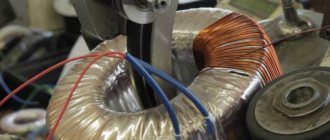
The calculation of the supply transformer comes down to determining the required sections of the magnetic circuit, the primary and secondary windings and the number of turns.
For a device designed to cut metal up to 12 mm at a current of 50A, an open circuit voltage of 200V and a mains voltage of 220V, these parameters are:
- magnetic core cross-section – 107 mm²
- primary winding – 225 turns of copper wire Ø4.7 mm;
- secondary winding – 205 turns of copper wire Ø5.04 mm².
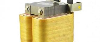
Transformer manufacturing
Due to the fact that the transformer must have a “soft” characteristic, the coils are located separately from each other. When using an O-shaped core, they are located on different rods; on an W-shaped magnetic core, the windings are located along the middle part.
The coils are wound according to the calculated parameters on the frames of their electrical cardboard. The finished windings are wrapped with glass tape or keeper tape and coated with paint.
After winding the windings and assembling the magnetic circuit, a diode bridge of 4 diodes with radiators, assembled on a textolite platform, is attached and connected to the transformer. The assembled transformer is placed in the housing, and the outputs of the windings and diode bridge are connected to the terminals on the front panel. The connection is made according to the schematic diagram, taking into account the presence of ammeters, voltmeters, starters and other parts.
An oscillator connected in series with the welder has a high high frequency output voltage. Therefore, it is necessary to use high-frequency diodes in the rectifier or install a separate diode bridge, specifically for the pilot arc.
About using a transformer or inverter
Most often, when you plan to assemble a plasma cutter, either an inverter or a special transformer is used as the power source. Each of these options has its own advantages, but in order to understand which one is suitable, you need to know exactly what technical characteristics your plasma cutter should have; accordingly, you need to know the features of the inverter and transformer.
The advantages of a plasma cutter made on the basis of an inverter are as follows: on average, its efficiency is one third higher than that of analogues that contain a transformer; they are the most efficient and economical. This device ensures arc stability. The disadvantages include the fact that the work is carried out exclusively with materials of insignificant thickness.
If a transformer is used as a basis, then such a unit will certainly be bulky and require an additional platform for use. But a significant advantage is that it allows you to work with fairly massive and thick parts. Such devices are installed either in rooms specially equipped for them or on mobile platforms.
Therefore, if you do not plan to cut particularly large objects, then it is recommended to use a plasma cutter made from an inverter. The principle is simple: you need to connect the power source you already have at your disposal and other parts, following a certain sequence.
Other components
In addition to the plasma torch and transformer, there are other elements in the plasma cutting unit.
Compressor
The most common working gas is compressed air. It can be used when cutting almost all metals and alloys. The source of compressed air is a compressor. It can be used in any design, the minimum performance depends on the thickness of the metal:
- 16 mm – 140 l/min;
- 20 mm – 170l/min
- 30 mm – 190 l/min.
For more stable operation, a receiver with a capacity of 50 liters or more is required; the pressure created by the compressor must be more than 4.5 Bar.
Cables and hoses
To operate an air-cooled plasma cutter, the cable-hose package consists of the following elements:
- Power cable. Its cross section depends on the rated power of the device. With a current of 50A, sufficient to cut metal 10 mm thick and a vinyl-insulated wire, it is 6 mm². When using a cable in heat-resistant insulation, the cross-section is correspondingly reduced. You need 2 of these cables - one in a cable-hose package for the electrode and the second for ground.
- Wire for pilot arc. The cross-section is sufficiently 1.5 mm². According to the permissible heating, a thinner cable is allowed, but it has insufficient mechanical strength.
- Air supply hose. Inner diameter 10 mm.
- Wires for connecting a microswitch.
Oscillator
This is a device that increases the XX voltage of the welding transformer to a value that ensures the appearance of an electric arc without preliminary contact of the electrode and the ground.
Oscillators used in plasma cutting units are connected in series with a transformer and add 220V AC to the DC voltage, with a frequency of up to 250kHz and a voltage of up to 6kV.
This device itself does not produce a current that is dangerous to human health and, moreover, is not capable of creating an arc for welding or cutting metal. The main purpose of this device is to create a spark between the electrodes. This spark is a conductor and “paves the way” for the welding rectifier.
Advice! Instead of an oscillator, it is allowed to use an electronic car ignition.
What does a plasma cutter consist of?
The plasma cutter consists of several units:
- plasmatron (it contains a nozzle (anode) and an electrode (cathode));
- power supply unit;
- oscillator;
- compressor;
- a set of cable hoses (the hose may deserve special consideration).
Assembly diagram of a plasma cutter for manual cutting.
Plasma torch
There are two ways to manufacture a plasma torch:
- assemble from a set of purchased components;
- Using drawings and instructions from the Internet, assemble it yourself.
In both cases, special attention should be paid to observing the principle of plasma cutting of metal.
Plasma torch composition - cross-sectional diagram
Power supply
The power source for the plasma cutter can be:
- transformer. It is not sensitive to voltage changes and allows you to cut thick metal, but it has low efficiency;
Welding transformer “TDM-303 U2 (Al)” - inverter The only drawback is that it does not allow cutting thick workpieces. Advantages: high efficiency, cheaper, lighter and more economical than a transformer.
Inverter multifunctional welding machine “Brima CT-416”.
Thus, you can independently wind a transformer of the required power and use it.
Oscillator
The plasma torch in the plasma cutter generates and generates a burning stream of ionized air. This flow is ignited by a device called an oscillator.
Compressor
The compressor, as the name suggests, supplies air. But not just air. It must provide a vortex air supply, which will force the cathode spot of the plasma arc to be located exactly in the center of the electrode. If this does not happen, then problems with the arc are possible.
It is better to buy a specialized compressor, otherwise you will have to install an air purification system in a standard one.
Compressor
Thus, you can build a homemade plasma cutter. With careful adjustment, you will achieve good cut quality with significant savings in material resources.
Homemade plasma cutter.
Examination
To check the assembled device, it is necessary to make a test cut of the metal:
- supply power to the transformer;
- after 10 minutes, turn off and check the windings for heating;
- if they are cold, reapply power;
- turn on the compressor;
- after filling the receiver, open the air valve and direct the air flow through the plasmatron;
- by pressing the microswitch button, light the auxiliary arc;
- If available, make a test cut of the metal.
After completing the tests, disconnect the device from the mains and again check all elements for heating.
Safety rules when working with a plasma cutter
The plasma cutting process, if operating rules are not followed, is dangerous to the health and life of people. The main harmful factors are:
- Splashes of molten metal. During the cut, the plasma stream melts the metal and blows it out of the part being cut. Contact of molten drops with flammable substances leads to their ignition, and contact with skin causes severe burns, up to IV degree (charring). For protection, it is necessary to direct the plasma flow away from people and flammable materials.
- Harmful gases and dust. During cutting, the metal not only melts, but also burns. The resulting smoke is harmful to health. In addition, contaminants on the surface of parts burn. Therefore, the workplace must be equipped with exhaust ventilation and work in a respirator.
- Bright light. During the operation of electric welding and cutting with plasma formed by an electric arc, in addition to visible light, ultraviolet radiation appears. This type of radiation causes burns to the retina of the eyes. For protection, the workplace is fenced with portable shields, and the cutter must use a protective shield.
- Temperature. After completion of work, the edges of the part remain heated to a high temperature for some time and touching them can lead to burns. To avoid such injuries, cut parts should only be touched with protective gloves or after sufficient time for the edges to cool.
Machine cost
Making a plasma cutting machine with your own hands is an expensive pleasure, both in terms of financial costs and time.
In addition to plumbing skills, you will need professional engineering thinking and knowledge of electronics and electrical engineering. In a specialized workshop where specialists from various fields work, it is quite possible to build CNC walls. The cost of a homemade machine, taking into account all the costs of purchasing components and paying employees, will be in the range of 600-800 thousand rubles. Buying a machine with the same (approximately) capabilities from a not very well-known manufacturer will cost about 1.2-1.5 million.
Taking into account the fact that a self-assembled machine is maximally adapted to specific needs and is 100% repairable without the involvement of third-party service providers (and expensive ones), this is another argument in favor.
Average cost of a transformer plasma cutter assembled by yourself
The cost of a homemade plasma cutter depends on the price of components. Ideally, such a device is assembled from various old junk and spare parts available in the workshop.
In any case, you should focus on the price of a store-bought plasma cutter, which depends on the thickness of the metal being cut, the availability of additional accessories, the manufacturer’s company and other factors.
The average cost of such devices depends on the thickness of the metal being cut:
- up to 30 mm – 150–300 thousand rubles;
- 25 mm – 81–220 thousand rubles;
- 17 mm – 45–270 thousand rubles;
- 12 mm – 32–230 thousand rubles;
- 10 mm – 25–20 thousand rubles;
- 6 mm – 15–20 thousand rubles.
Advice! Different manufacturers have different prices for components, so one way to save money is to purchase all the parts separately and assemble the device yourself from ready-made elements.
What is it needed for?
Each specialist periodically has to cut out parts from a sheet. To do this by machining means turning a lot of metal into chips. It makes no sense to buy expensive equipment just to use it once a week for a few minutes. The solution is to make a plasma cutter yourself. You can remake different types of rectifiers:
- inverter;
- transformer;
- rectifier.
Any device will work. The best option for those who like to tinker is to make a homemade plasma cutter from a welding inverter. When using gas cutting, productivity is lower and the cutting width is larger.
The main advantage of a plasma cutter is the use of ordinary air. The pressure is created by the compressor. There is no risk of explosion or poisoning, as when working with propane, oxygen and other gases.
The thickness of the cut sheet on household equipment with current up to 200A is limited to 40 - 50 mm. This power is enough for building a house and working in a home workshop. The semi-professional inverter is adjustable for thicknesses up to 100 mm.
For light and powerful equipment, it is enough to connect a compressor and replace the usual holder with a plasma torch, made with your own hands and purchased ready-made . The equipment equipment is easily changed, and inverter plasma cutters turn into ordinary devices on which welding is performed.
Parameters of plasma cutting of various metals
Despite the fact that all materials can be cut in one mode, to improve the quality of processing, different metals and alloys require different cutting modes, gas and equipment settings:
- Carbon steel – air, nitrogen, oxygen. Nozzle diameter 3 mm, cutting speed 0.3-5.5 mm/min.
- Stainless steel – air, nitrogen, hydrogen-argon mixture. Nozzle diameter 3 mm, cutting speed 0.3-5.5 mm/min.
- Aluminum - nitrogen, hydrogen-argon mixture. Nozzle diameter 2-3 mm, cutting speed 0.1-1.6 mm/min.
- Copper and alloys - air over 40 mm, nitrogen - 5-15 mm. Nozzle diameter 3-3.5 mm, cutting speed 0.4-3 mm/min
Information! The cutting speed depends on the installation current and the thickness of the part. In this case, it is important that the end of the arc “keeps up” with its beginning.
Plasma cutting of metal is a modern processing method. The presence of such a device, made from a welding transformer, in the workshop expands the capabilities of the master.
Manufacturing of the cathode block
The body of the cathode block is made of a polymer or textolite pipe with a diameter equal to the inner diameter of the outer cylinder of the anode block. An external thread is cut at the lower end of the pipe for connection to the body of the anode block. A thread is cut inside the housing to screw in the cathode holder. Body length 7-10 cm.
The cathode holder is made of bronze or steel and has different diameters in different areas. The lower section, 15-20 mm long, is made in the form of a pointed tube with a diameter of 8-10 mm and an internal diameter of 5-5.5 mm.
The middle section, 20-25 mm long, has a diameter equal to the internal diameter of the cathode block housing. In this area, a thread is cut for mounting on the body.
The diameter of the internal channel must be at least 5 mm. The upper section, 30-40 mm long, has a diameter of 10-15 mm. The internal diameter of this area is 6-7 mm. On the upper section of the holder, an internal thread is cut for attaching the electrode. From the outside, in the upper part, a thread is cut to a length of 20-25 mm to install a lock nut. This holder is best made on a lathe.
The cathode is made from a standard tungsten welding electrode with a diameter of 4 mm. Its end becomes pointed. A tungsten rod 40-50 mm long is firmly connected to the cathode shank, on which a thread is cut for fastening to the upper section of the cathode holder. Shank length 40-60 mm, diameter 6-7 mm. The upper part of the shank goes into an adjusting screw (of any shape), which, in turn, has a handle made of insulating material. The cathode is twisted into the internal channel of the holder so that its pointed end extends 5-10 mm from the lower (guide) section of the holder. By rotating the knob, the position of the cathode can be changed.
To limit and control the longitudinal movement of the cathode, a lock nut installed on the holder is used.
A hole is drilled in the body of the cathode block at the level of the lower section of the holder and a fitting is installed to supply plasma-forming gas. Gas is supplied through a tube located in the space between the bottom of the holder and the housing. The holder has a screw for connecting electrical power. A hole is drilled in the upper part of the case for the passage of wire (cable).