How to find out the power of a toroidal transformer by dimensions
There was a need for a powerful power supply. In my case, there are two magnetic cores: armored tape and toroidal. Armor type: ШЛ32х50(72х18). Toroidal type: OL70/110-60.
INITIAL DATA for calculating a transformer with a toroidal magnetic core:
- primary winding voltage, U1 = 220 V;
- secondary winding voltage, U2 = 36 V;
- secondary winding current, l2 = 4 A;
- core outer diameter, D = 110 mm;
- core inner diameter, d = 68 mm;
- core height, h = 60 mm.
Calculation of a transformer with a magnetic core type ШЛ32х50 (72х18) showed that the core itself is capable of producing a voltage of 36 volts with a current strength of 4 amperes, but it may not be possible to wind the secondary winding due to insufficient window area. Let's start calculating a transformer with a magnetic core of type OL70/110-60.
Software (on-line) calculation will allow you to experiment with parameters on the fly and reduce development time. You can also calculate using the formulas, they are given below. Description of the input and calculated fields of the program: a light blue field - the initial data for calculation, a yellow field - data selected automatically from the tables, if you check the box to adjust these values, the field changes color to light blue and allows you to enter your own values, green field – calculated value.
Formulas and tables for manual calculation of a transformer:
1. Secondary winding power;
2. Overall power of the transformer;
| Magnitude | Total power of secondary windings Pout, [W] | ||||
| 2-15 | 15-50 | 50-150 | 150-300 | 300-1000 | |
| Efficiency | 0,76-0,88 | 0,88-0,92 | 0,92-0,95 | 0,95-0,96 | |
3. The actual cross-section of the steel of the magnetic core at the location of the transformer coil;
4. The calculated cross-section of the magnetic core steel at the location of the transformer coil;
5. Actual cross-sectional area of the core window;
6. The value of the rated current of the primary winding;
| Magnitude | Total power of secondary windings Pout, [W] | ||||
| 2-15 | 15-50 | 50-150 | 150-300 | 300-1000 | |
| COS Φ | 0,85-0,90 | 0,90-0,93 | 0,93-0,95 | 0,95-0,93 | 0,93-0,94 |
7. Calculation of the wire cross-section for each of the windings (for I1 and I2);
| Magnetic core design | Current density J, [A/mm sq.] at Pout, [W] | ||||
| 2-15 | 15-50 | 50-150 | 150-300 | 300-1000 | |
| Ring | 5-4,5 | 4,5-3,5 | 3,5 | 3,0 | |
Equipment / Power tools, electricians and online calculators / Calculation of a transformer with a toroidal magnetic core
There was a need for a powerful power supply. In my case, there are two magnetic cores: armored tape and toroidal. Armor type: ШЛ32х50(72х18). Toroidal type: OL70/110-60.
INITIAL DATA for calculating a transformer with a toroidal magnetic core:
- primary winding voltage, U1 = 220 V;
- secondary winding voltage, U2 = 36 V;
- secondary winding current, l2 = 4 A;
- core outer diameter, D = 110 mm;
- core inner diameter, d = 68 mm;
- core height, h = 60 mm.
Calculation of a transformer with a magnetic core type ШЛ32х50 (72х18) showed that the core itself is capable of producing a voltage of 36 volts with a current strength of 4 amperes, but it may not be possible to wind the secondary winding due to insufficient window area. Let's start calculating a transformer with a magnetic core of type OL70/110-60.
Software (on-line) calculation will allow you to experiment with parameters on the fly and reduce development time. You can also calculate using the formulas, they are given below. Description of the input and calculated fields of the program: a light blue field - the initial data for calculation, a yellow field - data selected automatically from the tables, if you check the box to adjust these values, the field changes color to light blue and allows you to enter your own values, green field – calculated value.
Formulas and tables for manual calculation of a transformer:
1. Secondary winding power;
2. Overall power of the transformer;
Table No. 1.
| Magnitude | Total power of secondary windings Pout, [W] | ||||
| 2-15 | 15-50 | 50-150 | 150-300 | 300-1000 | |
| Efficiency | 0,76-0,88 | 0,88-0,92 | 0,92-0,95 | 0,95-0,96 | |
3. The actual cross-section of the steel of the magnetic core at the location of the transformer coil;
4. The calculated cross-section of the magnetic core steel at the location of the transformer coil;
5. Actual cross-sectional area of the core window;
6. The value of the rated current of the primary winding;
Table No. 2.
| Magnitude | Total power of secondary windings Pout, [W] | ||||
| 2-15 | 15-50 | 50-150 | 150-300 | 300-1000 | |
| COS Φ | 0,85-0,90 | 0,90-0,93 | 0,93-0,95 | 0,95-0,93 | 0,93-0,94 |
7. Calculation of the wire cross-section for each of the windings (for I1 and I2);
Table No. 3.
| Magnetic core design | Current density J, [A/mm sq.] at Pout, [W] | ||||
| 2-15 | 15-50 | 50-150 | 150-300 | 300-1000 | |
| Ring | 5-4,5 | 4,5-3,5 | 3,5 | 3,0 | |
8. Calculation of the diameter of the wires in each winding without taking into account the thickness of the insulation;
9. Calculation of the number of turns in the transformer windings;
n is the winding number, U' is the voltage drop in the windings, expressed as a percentage of the nominal value, see table.
In toroidal transformers, the relative value of the total voltage drop in the windings is significantly less compared to armored transformers.
Table No. 4.
| Torus, U' value | Total power of secondary windings Pout, [W] | ||||
| 8-25 | 25-60 | 60-125 | 125-250 | 250-600 | |
| U'1 | 7 | 6 | 5 | 3.5 | 2.5 |
| U'2 | 7 | 6 | 5 | 3.5 | 2.5 |
Table No. 5.
| Magnetic core design | Magnetic induction Vmax, [T] at Pout, [W] | ||||
| 5-15 | 15-50 | 50-150 | 150-300 | 300-1000 | |
| Thor | 1,7 | 1,7 | 1,7 | 1,65 | 1,6 |
10. Calculation of the number of turns per volt;
11. Formula for calculating the maximum power that the magnetic circuit can deliver;
Sst f – the actual cross-section of the steel of the existing magnetic circuit at the location of the coil;
Sok f – actual window area in the existing magnetic circuit;
Vmax - magnetic induction, see table No. 5;
J - current density, see table No. 3;
Kok - window fill factor, see table No. 6;
Kst is the coefficient of filling of the magnetic circuit with steel, see table No. 7;
The magnitudes of electromagnetic loads Vmax and J depend on the power removed from the secondary winding of the transformer circuit and are taken for calculations from tables.
Table No. 6.
| Magnetic core design | Window fill factor Coc at Pout, [W] | ||||
| 5-15 | 15-50 | 50-150 | 150-300 | 300-1000 | |
| Thor | 0,18-0,20 | 0,20-0,26 | 0,26-0,27 | 0,27-0,28 | |
Table No. 7.
| Magnetic core design | Filling factor Kst for steel thickness, mm | ||||
| 0,08 | 0,1 | 0,15 | 0,2 | 0,35 | |
| Thor | 0,85 | 0,88 | |||
Having determined the value of Sst*Sok, you can select the required linear size of the magnetic circuit, having an area ratio no less than that obtained as a result of the calculation.
How to find out the power of a toroidal transformer by dimensions
Currently, the most common types of magnetic cores are:
In some places you can still find W-shaped plate cores; the calculation of such transformers is similar to the calculation of W-shaped strip ones.
The toroidal transformer can be used at powers from 30 to 1000 W when minimal flux leakage is required or when minimum volume requirement is paramount. Having some advantages in volume and weight over other types of transformer designs, toroidal ones are at the same time the least technologically advanced (convenient) to manufacture.
Features of torus winding
The primary winding is made of copper wire in glass cloth or cotton insulation. Under no circumstances should rubber-insulated wires be used. For a current on the primary winding of 25 A, the wound wire must have a cross-section of 5-7 mm. On the secondary, it is necessary to use a wire of a much larger cross-section - 30-40 mm. This is necessary due to the fact that a much higher current will flow on the secondary winding - 120-150 A. In both cases, the wire insulation must be heat-resistant.
In order to properly rewind and assemble a homemade transformer, you need to understand some details of the process of its operation. It is necessary to correctly wind the wires. The primary winding is made using a wire of a smaller cross-section, and the number of turns themselves is much larger, this leads to the fact that the primary winding experiences very heavy loads and, as a result, can get very hot during operation. Therefore, the installation of the primary winding must be done especially carefully.
During the winding process, each wound layer must be insulated. To do this, use either a special varnished cloth or construction tape. The insulating material is pre-cut into strips 1-2 cm wide. The insulation is laid in such a way that the inner part of the winding is covered with a double layer, and the outer part, respectively, with one layer. After this, the entire insulating layer is coated with a thick layer of PVA glue. The glue in this case has a dual function. It strengthens the insulation, turning it into a single monolith, and also significantly reduces the humming sound of the transformer during operation.
Winding devices
Winding a torus is a complex and time-consuming process. In order to somehow lighten it, special winding devices are used.
- The so-called fork shuttle. The required amount of wire is first wound onto it, and then, using shuttle movements, the wire is sequentially wound onto the transformer core. This method is only suitable if the wire being wound is sufficiently thin and flexible, and the internal diameter of the torus is so large that it allows the shuttle to be pulled through freely. At the same time, winding occurs quite slowly, so if you need to wind a large number of turns, you will have to spend a lot of time on it.
- The second method is more advanced and requires special equipment for its implementation. But with its help you can wind a transformer of almost any size and at a very high speed. In this case, the quality of winding will be very high. The device is called a “breakable rim”. The essence of the process is as follows: the winding rim of the device is inserted into the hole of the torus. After this, the winding rim is closed into a single ring. Then the required amount of winding wire is wound onto it. And finally, the winding wire is wound from the rim of the device onto the torus coil. Such a machine can be made at home. His drawings are freely available on the Internet.
I'm already tired of assembling low-frequency amplifiers on microcircuits, my hands are itching, and I wanted to solder something serious. I decided to solder a transistor amplifier with bipolar power supply. The power source will be a linear power supply with a toroidal transformer, the winding of which I will talk about in this article.
First we need to decide on the power of the amplifier, the number of channels and load resistance.
I will have two channels, the output power will be approximately 100W per channel, the load resistance will be 4 Ohms.
You don’t have to bother and take a 300W transformer, but this is extra size and weight. Fortunately, if a class AB amplifier has an efficiency of approximately 50%, then in order to get 100W at the output, you need to consume 200W. If two channels are 100W each, then the consumption will be 400W. This is all approximate, and with the condition that the input signal will be a sinusoid with a constant amplitude. I don’t think that among reasonable people there are fans of listening to terrible squeaking in speakers.
The music we listen to has a sine wave waveform that varies in both frequency and amplitude. This signal will not always have a maximum amplitude; at such moments the electrolytic capacitor of the power source will be charged, and discharged at maximum amplitudes, thereby saving on transformer power. Again, if you are not a fan of listening to squeaking in the speaker system.
Let's calculate the power and voltage of our future transformer. Download and run the PowerSup program.
We fill in all the fields at the top of the program, set the quiescent current to 10mA, the preamplifier current to 0mA, select the purpose and type of signal according to the taste of the music you are listening to. Click “Apply”.
The program calculated the open-circuit voltage of the power supply, as well as the capacitance of the capacitors; these ratings are advisory in nature and are given for one arm.
Next, fill in the two lower windows in accordance with the recommended values and click “Calculate”. We got the output voltage of the transformer windings, I have 34.5V on each arm, the current of the secondary windings is 1.7A, diode parameters and connection diagram.
We have decided on the transformer parameters, now we download and run the Trans50Hz(3700) program. We will calculate the winding data.
My core is toroidal and has dimensions of 130*80*25. Fill in the fields of the program.
We set the induction amplitude to 1.2 T, or maybe one and a half (as in my case), this is for strip cores, and for plate cores we set it to 1 T. This parameter depends on the hardware.
Current density for class AB is from 3.5-4 A/mm2, for class A 2.5 A/mm2.
We set the currents and voltage of the secondary windings, click calculate.
Read also: Graphite grease temperature range
So, we got the number of turns of the primary and secondary windings, as well as the diameters of the wires.
You can do without calculations, wind approximately 900 turns, and periodically connect the winding to a 220V network in series through an incandescent lamp with a rated voltage of 220V.
If the lamp stays on, even at half heat, then we move on, checking periodically. As soon as the lamp stops glowing, it is necessary to measure the no-load current (but without the lamp, we connect the winding directly to the network), which should be 10-100 mA.
If the no-load current is less than 10mA, then this is not very good. Due to the high resistance, the transformer will heat up under the load. If the current exceeds 100mA, the transformer will heat up at idle. Although there are transformers with no-load current and 300mA, they heat up without load and hum terribly.
You can start winding the transformer itself. I need to wind 1291 turns of the primary winding with a wire whose diameter is 0.6 mm. Notice the diameter, not the cross-section! I have a 0.63mm wire.
I wrap it with rag tape. Once I wrapped the core with one lavsan tape, without electrical tape (or cardboard), and after winding several layers a breakdown occurred. Apparently the lower layers of the wire were crushed, and the varnish was damaged by the sharp edge of the core. Now, when winding toroidal transformers, I always wind the core with rag tape.
Next is a layer of Mylar tape.
Mylar tape can be bought in the store, in the form of a baking sleeve, which is cut into ribbons using a razor blade and a metal ruler.
We take a 40cm wooden ruler, saw through both edges so that the wire can be wound around it. We wind a large amount of wire (I had to wind 1300 turns several times).
Next, we decide on the direction of the winding, you can choose any, but with the condition that all windings (primary and secondary) will wind in the direction you choose.
I wind all the windings clockwise, as in the picture.
We secure the free end of the wire with tape, or thread, and wind the winding layer turn to turn.
Solder the wires of the primary winding. We isolate the areas of soldering and stripping of varnish.
I'll give you one little piece of advice. When soldering wires to the terminals of the primary winding, choose high-quality and durable wires, or do not solder them, but place them in dielectric tubes (heat shrink, cambric). While I was winding the secondary windings, my leads broke off due to repeated bending. I took the wires from the PC power supply.
We overlap 4-5 layers of lavsan tape taken from the baking sleeve.
Don’t forget to write down the number of turns in each layer on a piece of paper so you don’t forget. After all, winding a transformer can last not 1-2 days, but a month or several months, when there is no time, and you can forget everything.
We wind the remaining layers of wire in the same direction, between which we place layers of lavsan tape insulation.
The connection points must be soldered and insulated with heat shrink tubing.
When you have wound the required number of turns of the primary winding of the toroidal transformer, you need to connect the winding in series through a 220V lamp to the network, as mentioned above. The lamp should not glow. If it lights up, it means you have a small number of turns, or a short circuit between layers or turns (if the wire is bad).
Next, you need to measure the no-load current, but without the lamp (of course, if you didn’t have one on). Recommended no-load current 10-100mA.
My no-load current is 11mA.
Solder the tap. We isolate the primary winding from the secondary well, maybe 6-8 layers of Mylar tape.
The secondary winding can be wound according to the calculations made above, or using the following method.
We take a thin wire and wind two or three dozen turns over the “primary”. Next, we connect the primary winding to the network and measure the voltage on our experimental winding. I got 18 turns of 2.6V.
Dividing 2.6V into 18 turns, I calculated that one turn is equal to 0.144V. The more turns on the experimental winding are wound, the more accurate the calculation. Next, I take the voltage I need on one of the secondary windings (I have 35V) and divide by 0.144V, I get the number of turns of the secondary winding equal to 243.
Winding the “secondary” is no different. We wind it in the same direction, with the same shuttle, only we take the diameter of the wire from the calculations above. My wire diameter is 1.25mm (I didn’t have a smaller one).
As soon as we have the number of turns we need, we turn on our transformer to the network and measure the value of the output voltage; if it suits us, then we make a tap and continue to wind the second secondary winding.
You can make a tap and start winding a new secondary winding, that is, you will get four “secondary” terminals, or you can twist the end of the first “secondary”, with the beginning of the second “secondary”, like mine. Depends on what kind of performance you need and whether you will use the secondary windings separately.
Having wound the second “secondary”, we set the same voltage between the arms relative to the common wire, increasing or vice versa decreasing the number of turns.
We insulate the terminals (with heat shrink or cambric), and insulate the winding with Mylar tape. Our winding of the toroidal transformer is complete. I also added one 12V winding to power various devices (I haven’t decided which ones yet), for example, a preamplifier, tone control, fan, indicators.
The transformer is for sale. Price 1500 rub. [email protected]
Program for calculating power transformers with a frequency of 50 Hz – Trans50Hz(3700) DOWNLOAD
Program for calculating power supply parameters (50Hz) PowerSup DOWNLOAD
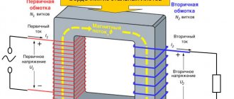
The main element of the power supply is the transformer. Sometimes it can be purchased in specialized stores, on the radio market or via the Internet. But most often it is not possible to buy a transformer with the necessary parameters. To make a transformer yourself, you first need to decide on the type of iron. The most common transformers are made from W-shaped plates. At the same time, transformers on toroidal iron (a donut made of iron tape) in comparison with transformers on armored cores made of W-shaped plates have less weight and dimensions. The toroids are also distinguished by better cooling conditions for the windings and increased efficiency. With a uniform distribution of windings around the perimeter of the toroidal core, there is practically no stray field and in most cases there is no need for shielding of the transformer. Although, when building a high-quality amplifier, you should not neglect the screen.
Read also: How to crimp a 4-wire network cable
In addition, even on the best iron with an induction of 15,000 Gauss in a toroidal transformer, the magnetizing current takes the form of pulses with a peak factor of 5.50. This is a source of powerful interference with a fairly wide spectrum. More or less sinusoidal current x.x. becomes at induction less than 6000 Gauss for steel 3410 and 8000. 9000 Gauss for 3425. Reduced induction significantly increases the cost and weight of the transformer, which is extremely undesirable for serial equipment. However, to reduce interference in an audio frequency power amplifier, it makes sense to reduce the induction in the power supply transformer. In this case, the rule works - “The lower the induction, the better.”
To calculate the parameters of a toroidal transformer, it is very convenient to use a calculator. It allows you to quickly calculate the parameters of a transformer, having a ready-made torus available. For Hi-End UMZCH, it is recommended not to select induction in a core made of Russian (Soviet) iron more than 1.0 Tesla. For imported iron (tor from an old UPS), 1.2 Tesla is acceptable. In this case, low magnetic interference and minimal acoustic noise from the transformer will be obtained.
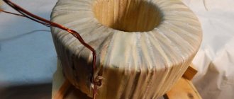
Before winding the toroidal transformer, it is necessary to prepare the selected core: first, chamfer with a semicircular file from all the sharp edges of the donut, then trace along the end of the torus with a pencil and cut out cheeks from thick paper (postcards), glue the cheeks to the sides of the torus, cover the outer and inner sides of the core with plain paper . Other options for core insulation are possible. The main thing is to prevent a possible short circuit of the primary winding to the transformer core as a result of possible pushing through of the insulation and damage to the varnish of the winding wire on the sharp edges of the torus during winding.
To wind a toroidal transformer, I use a shuttle made of wood or textolite at the ends of which I make dovetail-shaped cutouts. The shuttle can be easily made from a wooden student’s ruler 20–30 cm long. And so that it does not crack lengthwise when winding a coil of wire on it, the “dovetail” is strengthened with paper tape (3–4 turns across). When winding manually, you should use PELSHO, PESHO wires. As a last resort, you can use the widely used winding wire PEV-2 or PETV-2. Fluoroplastic PET film with a thickness of 0.01-0.02 mm, varnished cloth LShSS with a thickness of 0.06-0.12 mm or cambric tape are suitable as inter-winding and external insulation, but I used fluoroplastic film.
After winding the calculated number of turns of the primary winding, it is advisable to measure the no-load current of the transformer. To do this, we connect the tester in series with the primary winding in ammeter mode. To avoid any emergency situations, you can turn on a 220 V light bulb with a power of 40 W in series with the primary. The light will light if the number of turns is small. If the trans is wound correctly, the filament should have a pink tint. A toroidal transformer has high inrush currents; at the moment of startup, overloads can reach 160 times. Therefore, starting the transformer must be done not through the tester, but using a “jumper”, which then opens and current begins to flow through the tester.
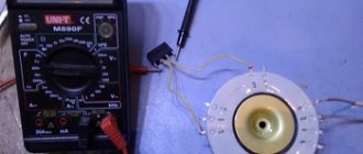
To measure no-load current I use the following circuit:
I turn on a 10 Ohm resistor in series with the primary winding of the transformer, apply mains voltage and measure the voltage drop across it. Accordingly, the no-load current is equal to I=U/R. In my case, 0.045 V / 10 Ohm = 0.0045 A. or 4.5 mA.
The no-load current rate for each transformer is individual and usually does not exceed 50 mA at a voltage of 220 V. Here the basic rule is “The lower the no-load current, the better”, the more similar the shape of the no-load current is to a sine.
For a toroid in the UMZCH power supply, the cold current is:
- 20-30 mA - “satisfactory”,
- 10-20 - “good”
- less than 10 mA - “excellent”.
To calculate the number of turns of the primary winding, I wind the secondary winding with any available wire (in my case, mgtf), apply mains voltage to the primary winding, and measure the voltage on the secondary winding.
My tester shows 0.581 V on 4 turns of the secondary. Accordingly, the number of turns of the primary winding will be equal to: U network x N secondary / U secondary. At the time of measurements, the network was 230 V. In numbers we get: 230 V x 4 turns / 0.581 V = 1583 turns.
A few more words about winding the transformer. In order to minimize the noise emitted by a toroidal transformer, it is necessary to evenly fill each layer of windings with winding wire. If you laid the turns to the right for the first half of the winding, then the second half of the winding must be laid to the left, without changing the direction of laying the turns themselves around the core. If it is necessary to wind two identical windings (typical for UMZCH), a double wire is wound onto the spool, and then the turns of two secondary windings are laid from the spool simultaneously, as shown in the photo.
In my case, three layers of primary are laid in one direction, and three more layers in the other. The primary conclusions are drawn as close to each other as possible. Two secondary coils were wound in the same way, two layers were laid in one direction and 2 more layers in the other. In compliance with these rules, I manufactured a 120 Watt toroidal transformer for Vasilich’s amplifier with an N-channel output stage by Alexey Nikitin, which ensured minimal interference to the input circuits of the UMZCH.
I will be glad if my experience in manufacturing toroidal transformers will be useful to you.
Winding of toroidal transformers
It is standard practice to additionally insulate the toroidal core from the windings, even if varnished wire is used. Electrical cardboard (GOST 2824) with a thickness of up to 0.8 mm is widely used (other options are possible). Common cases:
- The cardboard is wound with the previous turn captured on a toroidal core. The method is characterized as full overlap (half the width). The end is glued or secured with keeper tape.
- The ends of the core are protected by cardboard washers with cuts 10–20 mm deep, 20–35 mm in increments, covering the thickness of the torus. The outer and inner edges are covered with stripes. Technologically, the washers are the last to be assembled; the cut teeth are bent. A keeper tape is wound spirally on top.
- The cuts can be made on strips, then they are taken with a margin so that they are greater than the height of the torus, the rings are strictly in width, and are placed on top of the bends.
- Thin strips and rings of textolite are secured to the toroidal core with fiberglass tapes with a full overlap.
- Sometimes the rings are made of electrical plywood, getinax, thick (up to 8 mm) textolite with a margin of outer diameter of 1-2 mm. The outer and inner edges are protected with cardboard strips with a bend at the edges. There is an air gap between the first turns of the winding and the core. The gap under the cardboard is needed in case the edges under the wire fray. Then the current-carrying part will never touch the toroidal core. A keeper tape is wound on top. Sometimes the outer edge of the rings is smoothed so that the winding at the corners goes smoothly.
- There is a type of insulation similar to the previous one; on the inside, along the rings on the outer ribs, there are grooves to the core, where the strips are placed. The elements are made of textolite. A keeper tape is wound on top.
The windings are usually made concentric (one above the other), or alternating (as in the first experiment of Michael Faraday in 1831), sometimes called disk windings. In the latter case, a fairly large number of them can be wound through one, alternately: now high voltage, now low. Pure electrical copper (99.95%) with a resistivity of 17.24 - 17.54 nOhm m is used. Due to the high cost of the metal, refined aluminum is used for the manufacture of toroidal transformers of low and medium power. For other cases, restrictions on conductivity and plasticity affect.
In powerful transformers, the copper wire is of rectangular cross-section. This is done to save space. The core must be thick, allowing significant current to pass through, so as not to melt; a round cross-section will lead to excessive growth in size. The gain in uniformity of field distribution over the material would be reduced to zero. A thick rectangular wire is quite convenient to lay, which cannot be said about a thin one. Otherwise (according to design features), winding is carried out in exactly the same ways as in the case of a conventional transformer. Coils are made cylindrical, screw, single-layer, multi-layer.
Definition of Toroidal Transformer Design
For those interested in the issue, we recommend studying the book by S.V. Kotenev, A.N. Evseev on calculating the optimization of toroidal transformers (Hot Line - Telecom publication, 2011). We remind you: the publication is protected by copyright law. Professionals will find the strength (means) to purchase a book if necessary. According to the chapters, the calculation begins by determining the idle speed parameters. It describes in detail how to find active and reactive currents and calculate key parameters.
The printed publication, despite some controversial presentation, simultaneously makes it clear why a transformer connected to the circuit, without a load, does not burn out (the current energy is consumed by magnetization). Although it would seem that the obvious outcome of the event was predicted.
The number of turns of the primary winding is selected from the condition that the magnetic induction does not exceed the maximum value (before entering the saturation mode, where the value does not change with increasing field strength). If the design is carried out for a 230 volt household network, a tolerance is taken in accordance with GOST 13109. In our case, this means an amplitude deviation within 10%. We remember: the entire industry switched to 230 volts in the 21st century (220 is not used, it is cited in the literature as a “legacy of a difficult past”).