Cutter geometry
The geometry of the cutter is determined by the angles that are formed between the main surfaces of the workpiece and the cutting edges of the tool teeth.
Image #1: Cutter geometry: surfaces and corners
Let's start by describing the three main surfaces.
- Processable (1). This is the surface that needs to be processed.
- Processed (5). This is the surface obtained after processing.
- Cutting surface (7). Formed during the cutting process by the edges of the cutter teeth.
When calculating the cutter geometry, the initial planes are also used.
- Main (3). Passes through this point of the cutting edge and the axis of the cutter (4).
- Cutting plane (6). Passes through the main cutting edge of the cutter tooth and is located tangent to the processing surface.
- Secant (2). It is located perpendicular to the projection of the cutting edge onto the main plane.
The geometry of the cutter is determined by 8 angles.
Main angles. These are the rake angle γ, the clearance angle α and the point angle β.
- Angle of inclination of the main cutting edge ω.
- Angles in plan. These are the main angle ϕ, the auxiliary angle ϕ1 and the vertex angle ε.
- Auxiliary clearance angle α1.
Image No. 2: cutter geometry
Let's talk about the angles of cutter geometry in detail.
Angles of cutter geometry and their influence on cutting processes
Principal angles
The main angles of the cutters are set in the main cutting planes.
- Rake angles (γ). These are the angles between the cutting planes and the main flanks of the teeth. Rake angles have the greatest influence on cutting processes. As the rake angle increases, the resistance decreases and chip evacuation becomes easier. However, increasing the rake angles too much weakens the cutting edges. Therefore, the values are chosen depending on the hardness of the materials being processed.
Image No. 3: selection of rake angle values depending on the hardness of the materials being processed
As you can see, with increasing hardness and brittleness of materials, the values of the rake angles decrease, and with increasing softness and ductility, they increase.
- Back angles (α). These are the angles between the flanks of the teeth and the cutting planes. The values vary from 12 to 16°. Large clearance angles have fine-tooth cutters. Large-tooth cutters and tools with inserted knives have smaller clearance angles. The largest clearance angles have slotting and parting cutters. Values vary from 20° to 25°. Rear corners are not directly involved in the processing of workpieces. Their purpose is to reduce friction between the rear surfaces of the teeth and materials.
- Taper angles (β). Formed between the front and rear surfaces of the teeth. Values vary depending on the rake and back angles. As the tip angle increases, the strength of the cutter increases. However, there are pitfalls here too. As the sharpening angle increases, the processes of cutting teeth into the material being processed become more difficult, the processing temperature increases, and the power required to perform the operation increases.
Image No. 4: changing the value of the rake angle depending on the value of the point angle
Plan angles
There are also three of them.
- Principal plan angles (ϕ). These are the angles between the projections of the main cutting edges of the teeth on the main planes and the planes of the working ends of the tools. For end and disk cutters, ϕ has a certain constant value (90°). The values of the main angles in the plan can vary only for face mills. Range - 45–75°. The value of the angle ϕ affects the cutting process as follows. Decreasing the value leads to an increase in the strength and massiveness of the tooth tips, as well as to a lengthening of the active parts of the main cutting edges. This increases the wear resistance of cutters and reduces thermal stress. The negative effects of decreasing the angle ϕ include an increase in the cutting resistance force.
- Auxiliary plan angles (ϕ1). Reducing these angles leads to improved quality of machined surfaces. But because of this, the strength of the tooth tips decreases.
- Vertex angles (ε). These are the angles between the projections of the auxiliary and main cutting edges onto the main planes and the planes of the working ends of the cutters. The values do not affect cutting processes.
Image No. 5: diagram of the operation of a cutter with different angles in the lead
Secondary relief angle and main cutting edge angle
Let's talk about these cutter geometry angles.
- Auxiliary clearance angles (α1). They are located between the auxiliary rear surfaces of the teeth and the perpendiculars restored to the main planes. Auxiliary relief angles are usually half the size of the main ones (α). The values vary from 6 to 8°. Auxiliary clearance angles serve only to reduce the friction of the rear surfaces of the teeth on the processed materials.
- Angles of inclination of the main cutting edges (ω). As the values of these angles increase, the tops of the teeth become stronger. This increases the wear resistance of cutting tools.
Types of cutters for CNC machines
We continue to publish materials from the Milling Machine Operator's Handbook edited by V.F. Tongueless. This time we will analyze the types and designs of cutters.
A milling cutter is a multi-edged cutting tool. Processing with milling cutters ensures the production of parts with small errors in shape and size and high quality of the surface layer.
According to their shape and technological purpose, cutters are divided into types (Fig. 1.8). Face (Fig. 1.8, a) and cylindrical (Fig. 1.8, b) cutters are designed for processing open planes.
End (Fig. 1.8, c and d) and disk (Fig. 1.8, e) cutters are used when milling planes, grooves and shoulders. T-shaped (Fig. 1.8, e) and dovetail cutters (Fig. 1.8, g) process grooves of similar shapes. Shaped cutters (Fig. 1.8, h) are used to produce shaped surfaces.
There are other cutters, such as disc angle cutters, modular cutters, thread cutters, etc.
Rice. 1.8. Types of cutters (t - depth of cut; B - size of the machined surface)
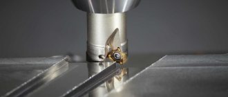
Elements of the cutter . The cutter consists of a body and a cutting part, which is made of tool steels, hard or mineral-ceramic alloys. Since the cutter tooth corresponds to the cutter, the surfaces and cutting edges of the cutter teeth are determined by analogy with the cutter.
For a turning cutter (Fig. 1.9) and a milling cutter (Fig. 1.10), the following elements and the parameters that determine them can be distinguished.
Rice. 1.9. Geometric parameters of turning cutter
Rice. 1.10. Elements and parameters of the cutter:
Aγ, Aα - front and rear surfaces; K - cutting edge; KN - groove; f - tooth chamfer; C - back of the tooth; γ — front angle; α—rear angle; β is the sharpening angle; δ—cutting angle
The surface along which the chips flow is called the rake surface Aγ. During the cutting process, it comes into contact with the cut layer and chips. The surface facing the workpiece during cutting is called the flank surface Aα. The intersection of the front and back surfaces forms the cutting edge. The part of the cutting edge that forms the larger side of the section of the cut layer is the main cutting edge K, and the other part that forms the smaller side is the auxiliary cutting edge K'.
The main flank surface faces the cutting surface and is adjacent to the main cutting edge. The secondary flank face faces the machined surface and is adjacent to the secondary cutting edge.
The section of the cutting edge where the two rear surfaces intersect is called the tip of the blade, and the radius along which this mate is made is called the tip radius.
The angles of the blade are set and measured relative to the main Pνc and working Rps planes (see Fig. 1.9, a). It is necessary to distinguish between the blade angles specified in the main and normal secant planes. The Pτ plane is perpendicular to the line of intersection of the main plane and the cutting plane, and the Рс plane is perpendicular to the cutting edge at the point under consideration. If the tool has a curved cutting edge, then the angles are measured in a section perpendicular to the tangent at a given point.
Rake angle γ is the angle between the front surface and the main plane. The angle measured in the normal cutting plane is called normal γn, and the angle measured in the main cutting plane is called the main rake angle γ. In this case, a positive rake angle [+γ] is distinguished if the cutting edge occupies the highest position on the front surface (see Fig. 1.9, b), and a negative rake angle [-γ] if the cutting edge is located below the points of the front surface.
When cutting with a tool with a negative rake angle, the deformation of the cut layer will be significantly greater, and therefore, greater forces and temperature in the cutting zone than when processing with a tool with a positive rake angle.
Rear angle α is the angle in the secant plane between the rear surface of the blade and the cutting plane. The angle measured in the normal cutting plane is called normal αн, and the angle measured in the main cutting plane is called the main rear angle α.
The size of the clearance angle affects the strength of the cutting wedge and the rate of wear growth.
The sharpening angle β is the angle between the front and rear surfaces of the blade; it determines the strength of the cutting tool. Cutting angle δ is the angle between the front surface and the cutting plane; δ ≈ β + α.
Blade angles are also determined relative to the secondary cutting edge.
The main angle ϕ is the angle between the projection of the main cutting edge onto the main plane and the direction of feed. Auxiliary plan angle ϕ′ is the angle between the projection of the auxiliary edge onto the main plane and the direction opposite to the feed direction. The angle at the tip of the cutter ε is the angle between the projections of the cutting edges onto the main plane.
The inclination angle of the main cutting edge λ is the angle in the cutting plane between the cutting edge and the main plane. The strength of the cutter tip, the conditions for cutting the cutter tooth into the workpiece, the direction of chip flow and other cutting parameters depend on the value of this angle.
There is a positive angle of inclination of the edge [+λ], if the tip of the cutter occupies the lowest position on the cutting edge (see Fig. 1.9, c), and negative [-λ], if it occupies the highest position. At λ = 0, the cutting edge is parallel to the main plane.
The cutter tooth (see Fig. 1.10) has the same elements as the cutter: the front surface Aγ, the rear surface Aα, the cutting edge K and the corresponding angles γ, α, β, δ. A tooth can also have a chamfer f and a back C - a surface adjacent to the front surface of one tooth and the back surface of the adjacent one. The groove Kn is a transitional element from one tooth to another.
The cutters have an end plane, i.e. a plane perpendicular to the axis of the cutter, and an axial plane, i.e. a plane passing through the axis of the cutter and the point under consideration on its cutting edge.
The main cutting edge K of the cutter performs the main cutting. For cylindrical cutters, the main cutting edge can be straight (along the cylinder generatrix), inclined (towards the cylinder generatrix) or helical. Cylindrical cutters do not have an auxiliary cutting edge.
Milling cutters with end teeth are distinguished:
- main cutting edge - an edge located at an angle to the cutter axis;
- auxiliary cutting edge - an edge located on the end part of the cutter;
- transition cutting edge - an edge connecting the main and auxiliary cutting edges.
A more complete picture of coordinate planes in accordance with GOST 25762–83 during milling is shown in Fig. 1.11, and when milling shaped surfaces - in Fig. 1.12.
Rice. 1.11. Coordinate planes for peripheral milling:
РVC and РVK - main planes: static and kinematic; RPS, RPK and RPI - cutting planes: static, kinematic and instrumental; RN - normal cutting plane; Pτ—main cutting plane; РΤИ, РΤС and РΤК - main cutting planes: instrumental, static and kinematic, respectively
Rice. 1.12. Coordinate planes for shaped milling (see designation of planes in Fig. 1.11)
Geometric elements of cutters in accordance with GOST 25762–83 are shown in Fig. 1.13–1.15.
Rice. 1.13. Geometric elements of a cylindrical cutter: 1 - front surface of the blade Aγ; 2 — main cutting edge K; 3 — auxiliary cutting edge K′; 4 - main rear surface of the blade Aα; 5 - auxiliary rear surface of the blade A′α; 6 - top of the blade
Rice. 1.14. Geometric elements of a corner end mill (see symbols in Fig. 1.13)
Rice. 1.15. Angles of the end mill: a - with insert teeth; b - with inserted square teeth
The letter designations of processing elements and planes are given in table. 1.1.
Shape and elements of teeth. Depending on the surface on which the cutter is sharpened, there are two main tooth designs:
- a pointed tooth, sharpened along the back surface (Fig. 1.16, a);
- a backed tooth, sharpened only along the front surface (Fig. 1.16, b).
Rice. 1.16. Shape of the cutter teeth: a - pointed; b - backed
The teeth are characterized by the following elements (Fig. 1.17):
- height h - the distance between the point of the cutting edge of the tooth and the bottom of the groove, measured in the radial section of the cutter perpendicular to its axis;
- width of the back surface of the tooth (see Fig. 1.10, chamfer f) - the distance from the cutting edge to the line of intersection of the back surface of the tooth with its back, measured in the direction perpendicular to the cutting edge;
- Sш - circumferential pitch of the teeth - the distance between the same points of the cutting edges of two adjacent teeth, measured along a circular arc centered on the axis of the cutter and in a plane perpendicular to this axis. The circumferential pitch can be uniform or uneven;
- the relief value hz (see Fig. 1.16, b) is a decrease in the relief curve between the cutting edges of two adjacent teeth.
Rice. 1.17. Tooth elements: h - height; f - chamfer; Sш - circumferential step
Rice. 1.18. Scheme of the formation of a helix: a - left; b - right
Elements and shape of grooves . Groove K (see Fig. 1.10) is a recess for removing chips, limited by the front surface of the tooth and the back surface of one and the back of the adjacent tooth. Grooves are divided into straight and helical. The groove is straight parallel to the axis of the cutter. The formation of a helix is shown in Fig. 1.18. If triangle ABC is screwed onto a cylinder so that the leg AB = πD coincides with the base of the cylinder with diameter D, then the hypotenuse AC forms a left or right helix on the cylinder. The pitch P of a helical line is the amount of its rise per revolution around the cylinder. The angle ω is called the angle of inclination of the helix, and the angle β is the angle of elevation of the helix. These angles are related to each other by the relationship: ω = 90 - β. They are determined by the formulas:
where π = 3.14.
Left helical groove (Fig. 1.19, a) - a groove directed along a helical line with an ascent from right to left. Right helical groove (Fig. 1.19, b) - a groove directed along a helical line with an upward rise from left to right.
Rice. 1.19. Direction of helical grooves: a - left; b - right
Important cutter parameters are the volume of the tooth cavity and the profile of the tooth cavity. The smoothness of the interface between the front surface and the back of the tooth must be such that the chips, under the influence of inertial forces, coolant or newly formed chips, are freely removed from the cavity. Increasing the parameters r and h (Fig. 1.17) in order to achieve more favorable conditions for chip placement is limited by the strength of the tooth. To improve chip removal, the front surface and tooth cavities of some cutters are polished.
Milling cutters with pointed teeth are easy to manufacture, easy to use and provide fairly high tool life. Such cutters are sharpened along the back surface, however, it should be borne in mind that as they are sharpened, the height of the tooth and the volume of its cavity decrease.
For cutters with back-relief teeth (see Fig. 1.16, b), the back is processed on turning-relief machines. Its profile corresponds to the Archimedean spiral, which ensures a constant profile of the front surface of the tooth. To maintain the values of the rear angles and profile, the teeth are ground along the front surface in the radial direction. Maintaining a consistent cutting edge profile is especially important for shape cutters. As the cutter teeth are sharpened, the cavity volume increases.
The disadvantages of these cutters are the small clearance angle α and zero rake angle γ, which makes cutting difficult and reduces tool life. Backed cutters have a higher cost compared to sharpened ones.
Milling cutter designs. Most cutter designs are standardized. In addition to their technological purpose, cutters are divided into solid, composite, with inserted knives and prefabricated heads.
Solid cutters are made entirely from tool material (high-speed steel or carbide). The cutters can be one-piece combined, i.e. the teeth are made of tool material, and the body is made of structural steel. The teeth are soldered onto the body or, if they are made of high-speed steel, welded onto it.
Solid cutters have great rigidity, which is their advantage. However, they also have disadvantages: changing the size of the cutters after regrinding; negative influence of the temperature of soldering or surfacing of cutting teeth on the quality (durability) of the tool; increased consumption of tool material.
Milling cutters with mechanical fastening of insert teeth (inserts) are currently the most common. Among the variety of designs for fastening cutting elements in such cutters, two main types can be distinguished - cutters with mechanical fastening of knives (cutters) and cutters with mechanical fastening of multifaceted non-sharpening plates.
Milling cutters with multifaceted inserts have a number of advantages, which determines their widespread use in practice. In general, during mechanical fastening, precise orientation of the cutting plate in the cutter body, the reliability of its fastening, the ability to quickly remove a worn plate and replace it with a new one, as well as the mechanization of these processes, and the minimum dimensions of the fastening unit must be ensured.
There are many different ways to fasten plates: screws, pins, levers, clamps, etc. They all have their advantages and disadvantages. One of the simplest ways to attach a multifaceted plate is shown in Fig. 1.20. A plate 1 made of tool material is mounted on a spacer 2, which is made of high-speed steel or hard alloy to reduce deformation from the effects of cutting forces and temperature. The gasket is secured with screw 3. The plate is oriented in the radial and vertical directions with stops 4, 5 and clamped with screw 7 through clamp 6. On the surface facing the falling chips, this clamp has a soldered carbide plate 8. For mechanical fastening, plates of two or three are used -, four-, five-, hexagonal and round shapes (Fig. 1.21).
Rice. 1.20. Scheme of fastening a quadrangular plate with a clamp: 1 - plate; 2 - gasket; 3 - screw; 4 and 5 — stops; 6 - sticking; 7 - screw; 8 - soldered plate
Rice. 1.21. Multifaceted non-grindable carbide inserts: a - square; b - hexagonal; c - round
Currently, either digital or alphanumeric symbols for mechanically fastened plates, depending on their shape, sharpening geometry, accuracy, etc. .
In these designations, the first two numbers (or the first letter) characterize the shape of the plate, the third number (or the second letter) determines the value of the relief angle, the fourth number (or the third letter) indicates the degree of precision in manufacturing the plate, and the fifth number (or the fourth letter) characterizes it design features.
The second part of the symbol consists of three groups of two-digit numbers that determine: the length of the cutting edge (mm), the thickness of the plate (mm), the value of the apex radius (mm), increased by 10 times.
For example, a hexagonal plate with a zero clearance angle, normal accuracy, with a central hole and chip flutes, dimensions: cutting length 11 mm, thickness 4 mm, apex radius 1.2 mm, made of VK6 alloy, will have the designations:
digital
11114 - 110412 VK8 GOST 19068–80*
and alphanumeric
HNUM - 110412 VK8 GOST 19068–80*.