How the device works
A transformer is an electrical device designed to transmit energy without changing its shape and frequency. Using the phenomenon of electromagnetic induction in its work, the device is used to convert an alternating signal or create galvanic isolation. Each transformer is assembled from the following structural elements :
- core;
- windings;
- frame for winding arrangement;
- insulator;
- additional elements ensuring the rigidity of the device.
The principle of operation of any transformer device is based on the effect of the appearance of a magnetic field around a conductor with an electric current flowing through it. This field also occurs around magnets. Current is the directional flow of electrons or ions (charges). By taking a wire conductor and winding it around a coil and connecting a potential measuring device to its ends, you can observe a surge in the voltage amplitude when the coil is placed in a magnetic field. This suggests that when a magnetic field is applied to a coil with a wound conductor, an energy source or energy converter is obtained.
In a transformer design, such a coil is called primary or mains . It is designed to create a magnetic field. It is worth noting that such a field must necessarily change in direction and magnitude all the time, that is, be variable.
A classic transformer consists of two coils and a magnetic circuit connecting them. When an alternating signal is applied to the contacts of the primary coil, the resulting magnetic flux is transmitted through the magnetic circuit (core) to the second coil. Thus, the coils are connected by magnetic power lines. According to the rule of electromagnetic induction, when the magnetic field changes, an alternating electromotive force (EMF) is induced in the coil. Therefore, a self-induction emf occurs in the primary coil, and a mutual induction emf occurs in the secondary coil.
The number of turns on the windings determines the amplitude of the signal, and the diameter of the wire determines the greatest current strength. If the turns on the coils are equal, the input signal level will be equal to the output. In the case where the secondary coil has three times as many turns, the amplitude of the output signal will be three times greater than the input - and vice versa.
The heating of the entire device depends on the cross-section of the wire used in the transformer. It is possible to select the correct cross-section using special tables from reference books, but it is easier to use an online transformer calculator.
The ratio of the total magnetic flux to the flux of a single coil sets the strength of the magnetic coupling. To increase it, the windings of the coils are placed on a closed magnetic circuit. It is made from materials with good electromagnetic conductivity, for example, ferrite, alsifer, carbonyl iron. Thus, three circuits arise in the transformer: an electrical circuit - formed by the flow of current in the primary coil, an electromagnetic circuit - forming a magnetic flux, and a second electrical circuit - associated with the appearance of current in the secondary coil when a load is connected to it.
The correct operation of the transformer also depends on the frequency of the signal . The larger it is, the less losses occur during energy transfer. This means that the dimensions of the magnetic circuit depend on its value: the higher the frequency, the smaller the dimensions of the device. Pulse converters are built on this principle, the manufacture of which is associated with development difficulties, so a calculator is often used to calculate a transformer according to the core cross-section, which helps to get rid of manual calculation errors.
Types of cores
Transformers differ from each other not only in their scope of application, technical characteristics and dimensions, but also in the type of magnetic circuit. A very important parameter affecting the magnitude of the magnetic field, in addition to the turns ratio, is the size of the core. The saturation ability depends on its value. The saturation effect occurs when, as the current in the coil increases, the magnitude of the magnetic flux remains unchanged, i.e., the power does not change.
To prevent the saturation effect from occurring, you will need to correctly calculate the volume and cross-section of the core, the size of which determines the power of the transformer. Therefore, the greater the power of the transformer, the larger its core should be.
By design, the core is divided into three main types:
- core;
- armored;
- toroidal.
The core magnetic circuit is a U-shaped or W-shaped structure. It is assembled from rods pulled together by a yoke. To protect the coils from the influence of external electromagnetic forces, armored magnetic circuits are used. Their yoke is located on the outside and covers the rod with the coil. The toroidal type is made of metal strips. Due to their ring design, such cores are the most economically advantageous.
Knowing the shape of the core, it is easy to calculate the power of the transformer. It is found using a simple formula: P=(S/K)*(S/K), where:
- S is the cross-sectional area of the core.
- K is a constant coefficient equal to 1.33.
The area of the core depends on its type, its unit of measurement is a centimeter squared. The result obtained is measured in watts. But in practice, it is often necessary to calculate the core cross-section based on the required power of the transformer: Sc = 1.2√P, cm2. Based on the formulas, we can confirm the conclusion: that the greater the power of the product, the larger the core used.
An example of selecting a current transformer for installing metering meters
It is necessary to select current transformers for the outgoing line feeding the TM-2500/6 transformer. The calculated current in normal mode is 240.8A, in emergency mode, when the transformer is overloaded by 1.2, the current will be 289A.
We choose a CT with a transformation ratio of 300/5.
1. Calculate the primary current at 25% load:
2. Calculate the secondary current at 25% load:
As you can see, the current transformers are selected correctly, since the following condition is met:
I2 > 10%*In counter, i.e. 1 > 0.5.
When choosing current transformers for metering meters, I recommend using tables II.4 – II.5.
Table II.5 Technical data of current transformers
Table II.4 Selection of current transformers
| Maximum rated power, kVA | Voltage | |||
| 380 V | 10.5 kV | |||
| Load, A | Transformation coefficient, A | Load, A | Transformation coefficient, A | |
| 10 | 16 | 20/5 | — | — |
| 15 | 23 | 30/5 | — | — |
| 20 | 30 | 30/5 | — | — |
| 25 | 38 | 40/5 | — | — |
| 30 | 46 | 50/5 | — | — |
| 35 | 53 | 50/5 (75/5) | — | — |
| 40 | 61 | 75/5 | — | — |
| 50 | 77 | 75/5 (100/5) | — | — |
| 60 | 91 | 100/5 | — | — |
| 70 | 106 | 100/5 (150/5) | — | — |
| 80 | 122 | 150/5 | — | — |
| 90 | 137 | 150/5 | — | — |
| 100 | 152 | 150/5 | 6 | 10/5 |
| 125 | 190 | 200/5 | — | — |
| 150 | 228 | 300/5 | — | — |
| 160 | 242 | 300/5 | 9 | 10/5 |
| 180 | — | — | 10 | 10/5 (15/5) |
| 200 | 304 | 300/5 | — | — |
| 240 | 365 | 400/5 | 13 | 15/5 |
| 250 | — | — | 14 | 15/5 |
| 300 | 456 | 600/5 | — | — |
| 320 | 487 | 600/5 | 19 | 20/5 |
| 400 | 609 | 600/5 | 23 | 30/5 |
| 560 | 853 | 1000/5 | 32 | 40/5 |
| 630 | 960 | 1000/5 | 36 | 40/5 |
| 750 | 1140 | 1500/5 | 43 | 50/5 |
| 1000 | 1520 | 1500/5 | 58 | 75/5 |
Typical parameter calculation
Quite often, radio amateurs use a simplified method when calculating a transformer. It allows you to perform calculations at home without using quantities that are difficult to know. But it’s easier to use an online calculator ready for calculating a transformer. In order to use such a calculator, you will need to know some data, namely:
- voltage of the primary and secondary windings;
- core dimensions;
- plate thickness.
After entering them, you will need to click the “Calculate” button or something similar in name and wait for the result.
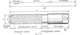
Rod type magnetic core
If it is not possible to calculate on a calculator, performing such an operation yourself is not difficult and manually. To do this, you will need to determine the voltage at the output of the secondary winding U2 and the required power Po. The calculation proceeds as follows:
- The load current is calculated: In=Po/U2, A.
- The value of the secondary winding current is calculated: I2 = 1.5*In, A.
- The power of the secondary winding is determined: P2 = U2*I2, W.
- The total power of the device is found: Pt = 1.25*P2, W.
- The current strength of the primary winding is calculated: I1 = Pt/U1, A.
- The required cross-section of the magnetic circuit is found: S = 1.3*√ Pt, cm².
It should be noted that if a device is designed with several terminals in the secondary winding, then in the fourth point all powers are summed up and their result is substituted instead of P2.
After the first stage is completed, proceed to the next stage of calculation. The number of turns in the primary winding is determined by the formula: K1 = 50*U1/S. And the number of turns of the secondary winding is determined by the expression K2= 55* U2/S, where:
- U1 - voltage of the primary winding, V.
- S—core area, cm².
- K1, K2 - number of turns in windings, pcs.
It remains to calculate the diameter of the wound wire. It is equal to D = 0.632*√ I, where:
- d — wire diameter, mm.
- I is the winding current of the calculated coil, A.
When selecting a magnetic core, you should maintain a ratio of 1 to 2 of the width of the core to its thickness. At the end of the calculation, the fillability is checked, i.e. whether the winding will fit on the frame. To do this, the window area is calculated using the formula: So = 50*Pt, mm2.
Autotransformer Features
Autotransformers are calculated similarly to simple transformers, only the core is determined not for the entire power, but for the power of the voltage difference.
For example, the power of the magnetic circuit is 250 W, the input is 220 volts, and the output needs to be 240 volts. The voltage difference is 20 V, with a power of 250 W the current will be 12.5 A. This current value corresponds to a power of 12.5 * 240 = 3000 W. The mains current consumption is 12.5+250/220=13.64A, which exactly corresponds to 3000W=220V*13.64A. The transformer has one 240 V winding with a 220 V tap, which is connected to the network. The section between the outlet and the outlet is wound with a wire rated at 12.5A.
Thus, an autotransformer allows you to obtain significantly more output power than a transformer with the same core with a low transmission coefficient.
Toroidal type transformer
Toroidal transformers have a number of advantages over other types: smaller size, lighter weight and, at the same time, higher efficiency. At the same time, they are easily wound and rewound. Using an online calculator to calculate a toroidal transformer allows you not only to reduce the manufacturing time of the product, but also to experiment on the fly with different input data. The following data is used:
- input winding voltage, V;
- output winding voltage, V;
- output winding current, A;
- outer diameter of the torus, mm;
- internal diameter of the torus, mm;
- torus height, mm.
It should be noted that almost all online programs do not demonstrate particular accuracy when calculating pulse transformers. To obtain high accuracy, you can use specially developed programs, for example, Lite-CalcIT, or calculate manually. For independent calculations, use the following formulas:
- Output winding power: P2=I2*U2, W.
- Overall power: Pg=P2/Q, W. Where Q is the coefficient taken from the reference book (0.76−0.96).
- The actual cross-section of the “iron” at the location of the coil: Sch= ((Dd)*h)/2, mm2.
- Calculated cross-section of the “iron” at the location of the coil: Sw =√Pq/1.2, mm2
- Torus window area: Sfh=d*s* π/4, mm2.
- The value of the operating current of the input winding: I1=P2/(U1*Q*cosφ), A, where cosφ is a reference value (from 0.85 to 0.94).
- The wire cross-section is found separately for each winding from the expression: Sp = I/J, mm2., where J is the current density taken from the reference book (from 3 to 5).
- The number of turns in the windings is calculated separately for each coil: Wn=45*Un*(1-Y/100)/Bm* Sch pcs., where Y is a table value that depends on the total power of the output windings.
- It remains to find the output power and the calculation of the toroidal power transformer is considered completed. Pout = Bm*J*Kok*Kct* Sch* Sfh /0.901, where: Bm - magnetic induction, Kok - wire filling coefficient, Kct - iron filling coefficient.
All coefficient values are taken from the radio equipment reference book (REA). Thus, it is not difficult to carry out calculations manually, but you will need accuracy and access to reference data, so it is much easier to use online services.
Formulas for calculating the number of turns of a transformer
Let's transform the formulas. We get:
[Number of turns of the primary winding
] = 2.5E5 [
Amplitude value of the input voltage, V
] / [
Frequency, Hz
] / [
Cross-sectional area of the magnetic circuit, sq.
mm ] / [
Maximum acceptable induction, T
]
Here is a selection of materials for your attention:
Design of power supplies and voltage converters Development of power supplies and voltage converters. Typical schemes. Examples of finished devices. Online payment. Opportunity for authors
The practice of electronic circuit design. The art of device development. Element base. Typical schemes. Examples of finished devices. Detailed descriptions. Online payment. Opportunity to ask questions to the authors
[Number of turns of the secondary winding
] = [
Number of turns of the primary winding
] * [
Amplitude value of the voltage of the secondary winding, V
] / [
Amplitude value of the input voltage, V
]
As we see from the formulas, the number of turns does not depend on the magnetic permeability of the core. Since a core with a gap is equivalent to a core with a lower magnetic permeability, but without a gap, the number of turns also does not depend on the size of the gap. But the no-load current of the transformer depends on the permeability (and the gap). If It is inversely proportional to this value. Since we are usually interested in reducing the no-load current, then, if there are no contraindications, it is better to use a material with greater permeability.
Read also: Soldering flux - what is it?
Recommendations for assembly and winding
When assembling a transformer with your own hands, the core plates are assembled “over the roof”. The magnetic core is tightened with a clip or hairpin nuts. In order not to damage the insulation, the studs are covered with a dielectric. You need to tighten the hardware with force: if it is not enough, a hum will occur during operation of the device.
The conductors are wound onto the coil tightly and evenly, each subsequent row is insulated from the previous one with thin paper or Mylar film. The last row is wrapped with keeper tape or varnished cloth. If a tap is made during the winding process, the wire breaks, and a tap is soldered in place of the break. This place is carefully isolated. The ends of the windings are secured with threads that tie the wires to the surface of the core.
There is a trick: after the primary winding, you should not wind the entire secondary winding at once. Having wound 10-20 turns, you need to measure the voltage at its ends.
Based on the obtained value, you can imagine how many turns will be required to obtain the required amplitude of the output voltage, thereby controlling the resulting calculation when assembling the transformer.