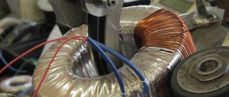
Toroidal transformer and its calculation
In order to greatly facilitate the calculation of a toroidal transformer, you need to know the following data:
- The output voltage that will be supplied to the primary winding U.
- External core diameter D.
- Core inner diameter d.
- Magnetic core
The cross-sectional area S will determine the power of the transformer. The optimal value today is considered to be 45-50 cm. Calculating this value is quite simple and can be done using the formula:
The most important characteristic of the core is the area of its window S. This parameter will determine the intensity of excess heat removal. The optimal value of this parameter can be 80-100 cm. It is calculated using the formula:
Thanks to these values, you can easily calculate its power using the formula:
P = 1.9 * Sc * S, where Sc and S must be taken in square centimeters, and P will be obtained in watts. Then you will need to find the number of turns per volt:
Once the value of k becomes known to you, you can calculate the number of turns in the secondary winding:
It is better to make calculations if you use the voltage on the secondary winding as the initial value:
W1 = (U1 * w2) / U2, where U1 is the voltage that is supplied to the primary winding, and U2 is removed from the secondary.
The easiest way to regulate the welding current is by changing the number of turns in the primary winding, since there is less voltage here.
How to check your device
Materials needed to test a toroidal transformer: Circuit diagram showing how the transformer is connected and (Digital Electronic Multimeter Tester or Analog Multimeter Tester).
The first step is to visually inspect the transformer and check for any odor. Overheating may cause the transformer to malfunction, if there are burn marks or the outer part of the winding is visible from the outside, the transformer must be replaced and there is no need for further tests to be carried out.
Checking a toroidal transformer.
Likewise, a burning smell is an indication that the transformer is overheating. If no further damage is visible except for the smell, further tests can be carried out to determine whether the transformer is in working order or not.
Input and output voltage information is usually clearly marked on the transformer, but the safest option is to obtain a circuit diagram from the product manufacturer.
Step-by-step check instructions
The voltage supplied to the primary winding must be clearly indicated on the circuit diagram and transformer housing. Likewise, the output voltage supplied at the secondary winding should be clearly indicated on the circuit diagram and transformer body. You must know the input and output voltages in order to check if the transformer is working correctly.
It will be interesting➡ What is a transformer substation
A transformer is not capable of converting alternating voltage into direct current voltage. Diodes and capacitors are used to convert AC voltage.
For those who liked it, the material is on the topic: what are current transformers.
The circuit diagram will show how the transformer's output voltage is converted from AC to DC voltage. You will need this information to determine whether to complete measurements taken with the multimeter tester in AC mode or DC mode. Begin the test by connecting power and connections to the product. Next follow the instructions:
- Switch the digital multimeter tester (with screen) or analog multimeter tester to AC voltage mode.
- To confirm the correct input voltage for the transformer, check the voltage by touching the red probe to the positive terminal and the black probe to the negative terminal of the main input transformer.
- If the voltage readings are too low, it may be due to problems with the transformer or circuitry.
- It is necessary to remove the transformer from the input circuit and check the input power represented by the circuit. If the reading is in line, then the transformer is faulty and if the reading remains unchanged, then the circuit is faulty.
- To check the output voltage, you first need to determine whether the output voltage is AC or DC.
- Set the digital or analog multimeter tester to the desired mode for testing.
If capacitors and diodes are used to convert the AC output voltage to DC voltage, then a reading that is too low may be caused by a faulty transformer or faulty capacitors and diodes. The video will tell you more about the device.
Remove the toroidal transformer with the output circuit and check the output voltage of the transformer. Don't forget to change the tester's multimeter mode to AC voltage. If the output voltage is in the line, the transformer is working correctly, then the problem will then be with the capacitors and diodes.
Toroidal transformers that emit a constant humming sound will soon fail and need to be replaced. Always remember to be careful not to touch the circuit when performing tests. Accidental contact with live circuitry may result in personal injury.
Manufacturing of a toroidal core
Toroidal transformers contain a complex core in their design. Transformer steel is considered the best material for its manufacture. In order to make the core of a toroidal transformer you need to use steel tape. It must be rolled into a roll, which will have the shape of a Thor. If you already have such a form, then no problems should arise.
If the value of the internal diameter d is insufficient, then part of the tape must be unwinded. As a result, both diameters will increase and the entire surface area will increase. True, this may reduce your cross-sectional area.
You can also find a good ready-made core on a laboratory autotransformer. You should rewind its windings. Instrument transformers have a simpler core.
Another method for manufacturing a toroidal core is the use of plates from a faulty industrial transformer. First, you will need to make a hoop from these fasteners. Its diameter should be 26 cm. The plates must be gradually inserted inside this hoop. Make sure that they do not unwind.
If the toroidal transformer reaches the required cross-section, then its magnetic circuit is ready. To increase S you need to make two toroids. They must be the same size. Their edges will need to be rounded with a file. You need to make two special rings and two strips for Thor from cardboard. After applying them, all elements should be wrapped with insulating tape. Now your magnetic circuit is ready.
Winding a toroidal transformer
Winding a toroidal transformer is a rather complex process that takes a lot of time. The toroidal transformer has one of the most complex windings. The easiest way is to use a special shuttle. A wire of the required length should be wound around it and then through the holes. It has a complex design, but this does not affect the operating principle of the toroidal transformer. After passing through the shuttle, a corresponding winding will begin to form.
Read also: DIY knife sharpener drawings
The shuttle is usually made of wood. Its thickness is 6 mm, length is 40 cm, and width is 4 cm. You should make semicircular cutouts at its ends. To estimate its length, you need to wind the wire around the shuttle, and multiply the value by the number of turns. In this case, the margin should be 20%.
Winding must be done using a circular shuttle. Bent plastic pipes or a hoop can serve as a blank. The hoop must be sawed in one place and threaded through the inner window of the core. The wire should be secured in several places with electrical tape. It will prevent your wire from falling apart.
We hope that thanks to this article you will be able to make a toroidal transformer yourself.
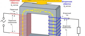
Transformer is translated from Latin as “converter”, “converter”. This is a static type electromagnetic device designed to convert alternating voltage or electric current. The basis of any transformer is a closed magnetic circuit, which is sometimes called a core. Windings are wound onto the core, of which there can be 2-3 or more, depending on the type of transformer. When an alternating voltage appears on the primary winding, a magnetic current is excited inside the core. It, in turn, causes an alternating current voltage with exactly the same frequency on the remaining windings.
The windings differ from each other in the number of turns, which determines the coefficient of change in voltage. In other words, if the secondary winding has half as many turns, then an alternating voltage appears on it, two times less than on the primary winding. But the current power does not change. This makes it possible to work with high currents at relatively low voltage.
Calculation method - step-by-step instructions
The calculation of the toroidal transformer itself is divided into two parts:
- You can directly calculate the power of a toroidal core in order to determine it; if you have a specific core, or a given power, then determine the dimensions of the future transformer.
- Calculation of the electrical part itself, which includes the number of turns in the windings, as well as what cross-section will be used in the windings and wire material.
Core calculation
We will produce it using a formula that already includes constants to simplify the understanding of its results. Next, all that remains is to substitute only variable values into the formula below, namely:
We recommend! How to make a gas burner yourself
“P=1.9*Sc*So” , where:
- P is the power that can be obtained using a core with such overall dimensions
- 1.9 – the result of mathematical operations on all constants for this type of transformers
- Sc - core area, unit of measurement square centimeters
- So is the area of the hole in the core body, in “sq. cm."
Formulas for calculating the cross-sectional area of a toroidal core
If the transformer made will have the main purpose of welding, then the dimensions of its core must be adequate, otherwise the resulting power of the device will not be enough to perform its functions. For example, take the following values and use a calculator to calculate. "P=1.9*70*70=9310 Watt"
Let's determine the number of turns of the primary winding
First of all, we will consider the calculation with a single primary winding, without adjustment. To do this, we first find out how many winding turns a toroidal transformer must have to produce 1 volt of voltage. Let's apply the following formula. K=35/Sc , where:
- K – number of turns per 1 volt of voltage.
- 35 is a constant that is the same for all types of toroidal cores.
- Sc is the area of the core, the unit of measurement is square centimeters.
Thus, if we have a core with an area of 70 "sq. see", then substituting the values in the formula, we get the following situation. “K=35/70=0.5” turns for each volt, and accordingly we find out the volume of the primary winding by applying the appropriate formula. “W1=U1*K” , where:
- W1 is the number of turns in the first winding.
- U1 is the required voltage at this point.
- K – number of turns per 1 volt of voltage.
“W1=220*0.5=110” – turns. Taking into account the fact that we are carrying out calculations for a welding transformer, we will take the operating voltage of the secondary equal to 35 volts, then based on a similar formula, we will obtain. “W2=35*0.5=17.5” – turns.
Calculation of the cross-section of the wires used
To calculate the required cross-sections, you need to understand what current will flow through them, this is the only parameter that affects the thickness of the material used, so, calculating the amount of current in the transformer windings: “I AC = 9310 Watts/220 Volts = 42.3 Amperes” With a secondary winding several more complicated, everything must rely on the arc voltage and welding current. “I weld.=(29 Volt-14)/0.05=300 Ampere” , where 29 volts is the average value of the welding arc. Now we check whether such power is possible for our device: 300 Amperes * 29 Volts = 8700 Watts.
We recommend! How to make an induction heater and oven from a welding inverter
This value fits well into the power of the toroidal transformer that we are calculating, so we consider 300 Amps to be the secondary winding current. Having carried out these simple calculations, for which you don’t even always need a calculator, you can proceed to determining the cross-section of the wires and their material.
From guidance documents such as, for example, “PUE”, it is known that for long-term operation, 1 square millimeter of copper cross-section is required for every 5 amperes of current, and when using aluminum, 2 amperes. Based on these data, we calculate the cross-section of the wires in the device for copper:
- Primary winding = 42.3/5 = 8.46 sq. mm, the closest cross-section standard is 10.
- Secondary winding=300/5=60 sq. mm, choose the next standard section in the direction of increase - 70.
We apply the load duration condition of 40 percent, since no one works under load all the time. In this case, the cross section can be reduced by half, then we get:
- 8.46/2=4.23 the nearest cross-section standard is -6 sq. mm.
- 60/2=30 next standard 35 sq. mm.
Types of transformers
Depending on the shape of the magnetic circuit, there are three types of transformers:
- Armored. It has a square shape with two side, one central and two transverse rods. In this case, only the central rod is effectively used. It is on this that the winding is put on. Therefore, the efficiency of this device is not very high. Forms two turns of magnetic field. This transformer is designed for heavy loads. This explains its very heavy weight.
- Rod. In some ways similar to the first type. The shape is half of an armored magnetic circuit. It consists of two lateral cores and two transverse ones. The magnetic field is single-turn, and, as a result, it has less power. The efficiency of such a transformer is 40%.
- Toroidal. It got its name due to its original shape. In mathematics there is such a thing as a toroidal surface. To put it simply, it is a voluminous circle or donut shape. Thanks to this shape of the magnetic core, toroidal transformers have the highest level of efficiency, approaching 100%. Therefore, such transformers are always smaller in size with the same power compared to other types. Due to the fact that the windings are evenly distributed over the entire area of the core, more efficient cooling of the turns occurs. Which, in turn, allows such devices to be loaded to the maximum without the risk of overheating.
Plate materials
Transformer cores are made of either metal or ferrite. Ferrite, or ferromagnetic, is iron with a special crystal lattice structure. The use of ferrite increases the efficiency of the transformer. Therefore, most often the transformer core is made of ferrite. There are several ways to make a core:
- Made from stacked metal plates.
- Made from wound metal tape.
- In the form of a monolith cast from metal.
Any transformer can operate in both step-up and step-down modes. Therefore, all transformers are conditionally divided into two large groups. Boost: The output voltage is greater than the input. For example, it was 12 V, it became 220 V. Step-down: the output voltage is lower than the input. It was 220, but became 12 volts. But depending on which winding the primary voltage is supplied to, you can turn the step-down transformer into a step-up transformer, which will turn 10 A into 100 A.
DIY toroidal transformer
A toroidal transformer, or simply a torus, is most often made at home as the main part for a home welding machine and more. In fact, this is the most common type of transformer, first manufactured by Faraday in 1831.
Advantages and disadvantages of the torus
Thor has undoubted advantages compared to other types:
- Relatively small in size.
- Very strong output signal.
- The windings are short and, as a result, these devices are characterized by low resistance and very high efficiency.
- Thanks to their shape, they are easy to install and also easy to dismantle if necessary.
The simplest torus consists of two windings on its ring-shaped core. The primary winding is connected to the source of electric current, the secondary winding goes to the electricity consumer. By means of a magnetic circuit, the windings are combined and their induction is enhanced. When the power is turned on, an alternating magnetic flux appears in the primary winding. Connecting to the secondary winding, this flux generates electromagnetic force in it. The magnitude of this force depends on the number of wound turns. By changing the number of turns, you can convert any voltage.
Read also: Do-it-yourself heating with diesel fuel
Calculation of the power of a toroidal transformer
Making a welding toroidal transformer at home begins with calculating its power. The main parameter of the future torus is the current that will be supplied to the welding electrodes. Most often, electrodes with a diameter of 2–5 mm are sufficient for domestic needs. Accordingly, for such electrodes the current power should be in the range of 110–140 A.
The power of the future transformer is calculated using the following formula:
U - open circuit voltage
cos f - power factor equal to 0.8
n - efficiency equal to 0.7
Next, the calculated power value is compared with the cross-sectional area of the core using the appropriate table. For home welding transformers, this value is usually 20−70 kV. cm depending on the specific model.
After this, using the following table, the number of turns of the wire is selected in relation to the cross-sectional area of the core. The pattern is simple: the larger the cross-sectional area of the magnetic circuit, the fewer turns are wound on the coil. The direct number of turns is calculated using the following formula:
U is the current voltage on the primary winding.
I - secondary winding current, or welding current.
S is the cross-sectional area of the magnetic circuit.
The number of turns on the secondary winding is calculated using the following formula:
Toroidal core
Toroidal transformers have a rather complex core. It is best made from special transformer steel (an alloy of iron and silicon) in the form of a steel strip. The tape is pre-rolled into a dimensional roll. Such a roll, in fact, already has the shape of a torus.
Where can I get a ready-made core? A good toroidal core can be found on an old laboratory autotransformer. In this case, it will be necessary to unwind the old windings and wind new ones onto a ready-made core. Rewinding a transformer with your own hands is no different from winding a new transformer.
Main advantages and disadvantages
When using toroidal transformers supplied with free twisted leads, it is possible to achieve savings of up to 64% of the occupied volume compared to conventional transformers with laminated cores (very often it is easier to connect equipment using leads from the transformer, rather than terminal blocks).
The toroidal (ring) core has an ideal shape, allowing the transformer to be manufactured using a minimum amount of material. All windings are symmetrically distributed over the entire circumference of the core, due to which the winding length is significantly reduced.
The main pros and cons of toroidal transformers.
This leads to a decrease in winding resistance and an increase in efficiency. Higher magnetic induction is possible since the magnetic current flows in the same direction that the silicon steel core is oriented during rolling. You can also note the advantages:
- low dispersion rates;
- less heating;
- low weight and size;
- Compact, easy to install in electrical equipment.
Higher current densities can be used in the wires since the entire surface of the toroidal core allows the copper wires to be effectively cooled. Iron losses are very low - a typical value is 1.1 W at 1.7 Tesla and 50/60 Hz. This provides very low magnetizing current, contributing to the amazing thermal load capacity of the toroidal transformer.
Toroidal transformer
Why is this the most popular type of transformer?
Any specialist will say that the toroidal shape of the core is ideal for a transformer for several reasons: firstly, it saves materials in production, secondly, the windings evenly fill the entire core, distributed over its entire surface, leaving no unused spaces, thirdly, Since the windings are shorter, the efficiency of toroidal transformers is higher due to the lower resistance of the winding wires.
Energy savings are another plus in favor of a toroidal transformer. Approximately 30% more energy is saved at full load, and approximately 80% at idle, compared to laminated magnetic cores of other forms. The dissipation rate of toroidal transformers is 5 times less than that of armored and rod transformers, so they can be safely used with sensitive electronic equipment.
Winding of a toroidal transformer.
Winding cooling is another important factor. The windings are effectively cooled by being arranged in a toroidal shape, hence the current density can be higher. Losses in the iron are minimal and the magnetizing current is much lower. As a result, the thermal load capacity of the toroidal transformer turns out to be very high.
It will be interesting➡ What is a pulse transformer and how to calculate it
With a power of a toroidal transformer up to a kilowatt, it is so light and compact that for installation it is enough to use a metal pressure washer and a bolt. All the consumer needs to do is select a suitable transformer based on load current and primary and secondary voltages. When manufacturing a transformer at the factory, the cross-sectional area of the core, the area of the window, the diameters of the winding wires are calculated, and the optimal dimensions of the magnetic circuit are selected, taking into account the permissible induction in it.
Features of torus winding
The primary winding is made of copper wire in glass cloth or cotton insulation. Under no circumstances should rubber-insulated wires be used. For a current on the primary winding of 25 A, the wound wire must have a cross-section of 5-7 mm. On the secondary, it is necessary to use a wire of a much larger cross-section - 30-40 mm. This is necessary due to the fact that a much higher current will flow on the secondary winding - 120-150 A. In both cases, the wire insulation must be heat-resistant.
In order to properly rewind and assemble a homemade transformer, you need to understand some details of the process of its operation. It is necessary to correctly wind the wires. The primary winding is made using a wire of a smaller cross-section, and the number of turns themselves is much larger, this leads to the fact that the primary winding experiences very heavy loads and, as a result, can get very hot during operation. Therefore, the installation of the primary winding must be done especially carefully.
During the winding process, each wound layer must be insulated. To do this, use either a special varnished cloth or construction tape. The insulating material is pre-cut into strips 1-2 cm wide. The insulation is laid in such a way that the inner part of the winding is covered with a double layer, and the outer part, respectively, with one layer. After this, the entire insulating layer is coated with a thick layer of PVA glue. The glue in this case has a dual function. It strengthens the insulation, turning it into a single monolith, and also significantly reduces the humming sound of the transformer during operation.
Winding devices
Winding a torus is a complex and time-consuming process. In order to somehow lighten it, special winding devices are used.
- The so-called fork shuttle. The required amount of wire is first wound onto it, and then, using shuttle movements, the wire is sequentially wound onto the transformer core. This method is only suitable if the wire being wound is sufficiently thin and flexible, and the internal diameter of the torus is so large that it allows the shuttle to be pulled through freely. At the same time, winding occurs quite slowly, so if you need to wind a large number of turns, you will have to spend a lot of time on it.
- The second method is more advanced and requires special equipment for its implementation. But with its help you can wind a transformer of almost any size and at a very high speed. In this case, the quality of winding will be very high. The device is called a “breakable rim”. The essence of the process is as follows: the winding rim of the device is inserted into the hole of the torus. After this, the winding rim is closed into a single ring. Then the required amount of winding wire is wound onto it. And finally, the winding wire is wound from the rim of the device onto the torus coil. Such a machine can be made at home. His drawings are freely available on the Internet.
Calculation of product parameters
Before winding a toroidal transformer at home, you will need to calculate its values. To do this you need to know the source data. These include: the output voltage, the outer and inner diameter of the core.
The power of the device is determined by the product of the areas S and Sо, multiplied by the coefficient: P=1.9* S * Sоk.
The cross-sectional area is calculated using the formula: S=h*(Dd)/2, where:
- S - cross-sectional area;
- h - height of the structure;
- D - outer diameter;
- d is the internal diameter.
To calculate the window area, the formula is used: Sok=3.14*d2/4.
The number of turns in the secondary winding is equal to the product W2=U2*50/Sok.
Next, it remains to calculate the number of turns in the primary. For this, the expression is used: W1=(Uin*W2)/Uout, where Uin is the input voltage, and Uout is the voltage at the output of the device.
This calculation method can be applied to almost any type of toroidal transformer. But for the calculation of some products there is its own methodology.
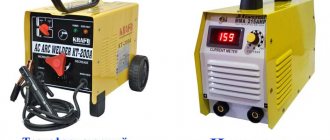
Welding device
This type of transformer is characterized by a high output current. The maximum current and voltage are used as input parameters. For example, for a device with a welding current of 200 amperes and a voltage of 50 volts, the calculation is as follows:
1. The power of the transformer is calculated: P = 200 A * 50 V = 1000 W.
2. The window cross-section is calculated: Sok = π * d2/ 4 = 3.14 * 144 / 4 (cm2) ≈ 113 cm².
3. Cross-sectional area: Sc=h * H = 2 cm * 30 cm = 60 cm².
4. Core power: Рс = 2.76 * 113 * 60 (W) ≈ 18712.8 W.
5. Number of turns of the primary winding: W1 = 40 * 220 / 60 = 147 turns.
6. Number of turns for the secondary winding: W2 = 42 * 60 / 60 = 42 turns.
7. The area of the secondary wire is determined based on the highest operating current: Spr = 200 A / (8 A/mm2) ≈ 25 mm².
8. The area of the primary wire is calculated: S1 = 43 A / (8 A/mm2) ≈ 5.4 mm².
This calculation option is applicable not only for welders, but can also be successfully used for other types. As you can see, no difficulties should arise during the calculation.
Current transformer device
It is not difficult to make a current transformer with your own hands, but before making it you will need to perform a calculation. This calculation differs from the generally accepted one due to the design features of the product. It starts with the required value of the secondary current (unit ampere): Iam = Iper / Ivt, where:
• Iper - the value of the primary winding current, multiplied by the number of turns in it;
• Ivt - the number of turns in the secondary winding.
In order to figure out how to correctly perform the calculation, it is easier to consider a practical example of a homemade current device. Let it be necessary to obtain 4 volts at the output of the current device, and limit the current to 5 amperes.
The step-by-step calculation method looks like this:
- Take a ferrite ring, for example 20x12x6 from 2000hM.
- 100 turns of wire are wound. These turns constitute the secondary winding, since the primary is simply one turn of wire passed through ferrite.
- The value of the current in the secondary will be equal to: I/Ktr = 5 / 100 = 0.05 A. where Ktr is the transformation ratio of the transformer (the ratio of the number of primary windings to the secondary).
- The size of the load shunt is calculated according to Ohm's law: R = U/I. It turns out R= 4/0.05 = 80 Ohm.
In this way, calculations can be performed for any required parameters. Regardless of the shape of the current at the input, the voltage at the output of the current device is always bipolar. It is the resistance, not the diode, that is used as the secondary winding shunt. If there is a need for a diode, then a resistor is connected first, and then a diode or diode bridge. In the second case, the resistance is included in the diagonal of the bridge.