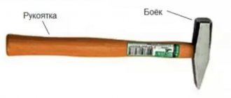
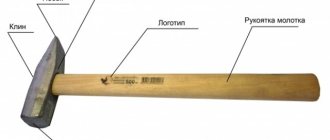
Classification and types
Depending on the type of energy carrier used, the following types of units described are distinguished:
- Steam-air hammer , which uses the energy of superheated steam.
- Pneumatic hammer , the energy carrier of which is compressed air.
- Hydraulic hammer , which deforms the workpiece by the force of the flow of the working liquid medium (water or oil).
- Hydraulic screw hammer , where, along with fluid energy, mechanical energy is also used.
- Mechanical hammer , for which the principle of direct conversion of potential energy/work into kinetic energy is implemented.
Hydraulic Hammer Steam Air Hammer
Air hammer
Classification is also carried out according to technological purpose; this determines the design features of the hammers. In particular, a forging hammer has free-standing racks, and a steam-air hammer is distinguished by the design of racks connected to the hammer using fasteners, spring-loaded parts.
The layout principle of all hammers is mainly vertical. The few variants of horizontal hammerless hammers - impactors - have not gained much popularity. The reason is the difficulty of holding a heated workpiece during pressure treatment. At the same time, shaking of the ground and foundation is significantly reduced, which makes working with such equipment more comfortable.
Construction of a frame structure for a forging hammer
A channel is used to make the frame. Typically, its parameters are selected based on which products will be processed. As a rule, a 12x8 cm channel is suitable for household equipment.
IMPORTANT TO KNOW: Types of desktop metal milling machines
The distance at which the channel sections will be located from each other is selected taking into account the size of the anvil - it can be 80-100 cm.
Either the same channel or an iron pipe are used as metal spacers.
In this case, the spacer in the front part of the frame - the future location of the anvil - must be mounted under the channel.
Since it is the front part of the forging installation that will be subject to heavy loads during the working process.
The rear spacer of the installation should be welded near the top level of the channels.
Structural components
In terms of its design, a typical forging hammer consists of the following components:
- power cylinder;
- rod;
- two side racks;
- Shabota;
- women;
- control systems.
In the cylinder, the pressure created by the superheated steam is redistributed, with the direction of the energy flow into the lower cavity, to which the rod is rigidly connected. A hammer head is attached to the opposite part of the rod, making reciprocating movements, thereby deforming the material. A forging hammer is distinguished by the presence of smooth strikers, while a steam-air hammer is equipped with a special tool - a forging die.
Diagram of operation of a pneumatic forging hammer
Current positioning is carried out by special guides on the side posts with a developed contact surface. Similar elements are provided on the side surfaces of the woman; as a result, fairly accurate blows are applied to the heated blank.
The chabot is a large and massive cast iron part: for operational reasons, the mass of the chabot should be at least 10 times greater than the mass of the falling parts. To reduce vibrations, the chabot is placed deep in the ground and installed on a vibration damper, which is large square oak boards.
Design and principle of operation
The functioning of a forging hammer is based on the dynamic impacts of the working body - the rod, connected to the head (the striking part of the machine) and devices that control the force of impact. Other required structural elements are:
- a piston connected to a woman;
- base (fixed on a solid surface);
- bed (guides for moving units are fixed on it);
- drive equipment;
- shield fence (for operator safety);
- electrical equipment;
- compressor cylinder (for pneumatic hammers).
Early machines were either foot or hand driven. A modern forging hammer is equipped with a convenient control system that minimizes the effort of the forge worker.
Rice. 1. Pneumatic hammer device.
(1 - working cylinder, 2 - compressor cylinder, 3 - piston, 4 - crank mechanism, 5 - woman, 6 and 7 - upper and lower strikers, 8 - cushion, 9 - air distribution mechanism, 10 - deformable workpiece)
Briefly, the device works like this:
- the workpiece is placed in the lower part of the hammer (usually the hammer);
- set the device to a certain impact frequency and set it in motion;
- after activating the hammer, the driven upper part hits the workpiece;
- the dynamic effect continues until the workpiece acquires the desired shape.
When a forging hammer operates, the reciprocating movement of the crank mechanism is converted into the same movement of the piston. This allows you to perform many operations on it.
Sequence of action
The forging hammer has a rather complex control system, which requires the blacksmith to have high production qualifications and appropriate experience. The fact is that any steam-air distribution mechanism constantly operates in a cycle of idle and working swings. The difference between them is the vibration amplitude: in the idle cycle it is, depending on the power of the unit, 10...50 mm, and in the working cycle it is determined by the initial height of the forging. Since with each new blow this parameter decreases and the metal cools, the force of the next impact should be greater, and this depends solely on the angle of rotation of the lever blocking (fully or partially) the holes of the control spool.
The principle of operation of double impact hammers is to carry out the following actions:
- Lifting to its top position (but not to the extreme, since in this case you can knock out the cover of the cylinder located on the sub-cylinder plate).
- Holding in a canopy while a heated blank is installed on the die.
- Downward acceleration, and for the first contact with the workpiece, the amount of compressed air (if a pneumatic hammer is used) or steam should be the greatest.
- Lifting the upper half of the die upward and removing the forging from the lower cavity (or its edging, if hot deformation is performed in several transitions).
Hot stamping technology involves applying up to 5...6 blows to the workpiece, depending on the complexity of the forging and the temperature of the metal. A specific deformation scheme is established in the operation flow chart.
The mechanism of the forging hammer
At the first stage of assembling the forging hammer mechanism, a lever is made. A striker is mounted on one end of it, and a counterweight is equipped on the other.
In this case, the design of the lever can be made either in prefabricated or monolithic form. How to make a lever correctly can be considered in more detail in the proposed video material.
The use of strip steel, but not pipes, will prevent bending of the lever during strong impacts. In this case, the steel must have a thickness of at least 25 mm and a width of about 70 mm.
Visually dividing the steel strip into three parts, at the end of the first part, a hole is made at one edge of the pipe for a section of pipe that will create conditions for rotation of the lever.
To do this, a pipe segment is inserted and welded into the finished hole; it will act as a bearing.
With a 70 mm wide steel strip, the hole should have a diameter such that there is 8-10 cm left to the edge of the strip, which will prevent premature repair of the installation due to deformation of the lever in this place.
Therefore, you can take a 50 mm product as a pipe for making a “bearing”.
The crossbar for the lever device is taken with a diameter that will allow it to rotate freely on the axis, but not “dangle”.
IMPORTANT TO KNOW: Review of equipment for cold metal forging
Video:
To prevent the forge hammer lever from moving during the working process, which would require repairs at the most inopportune moment, it is additionally secured with pins.
Fastening elements are installed using radial holes.
By welding, one end of the lever is equipped with a hammer, the other with a counterweight.
The striker must be made of high-strength tool steel, otherwise such a striker will be of little use.
Features of the use of hammers of other types
A pneumatic hammer installed in a single unit is usually equipped with an individual compressor unit. This type of pneumatic hammer does not have a high mass of falling parts, and therefore can be used for forging small products. A pneumatic hammer usually has a C-shaped frame, which is fastened with side posts for rigidity. The stamping area of the pneumatic hammer is thus open on three sides, which facilitates its maintenance.
The hydraulic hammer has limited use. Hydraulic forging units are often used in hot sheet stamping, when processing titanium alloys that have low plasticity in the cold state. The speed of the die in hydraulic hammers is lower, which is explained by differences in the density of oil/water compared to air/steam. The hydraulic actuator requires increased requirements for sealing seals; otherwise, its design is not fundamentally different from other schemes of the considered installations.
Download instructions for forging hammers Blacksmith KM1-25R, KM1-20R, KM1-16R
Mechanical drives of impact forging machines - with a belt, board, or spring-spring - are now rare, since in this case additional energy cannot be supplied to the deformation zone. Their design is quite simple, but the efficiency is low.
Air hammer
The basic operating principle of a pneumatic hammer: the drive operates under the influence of air masses filling the cylinder . The compressor piston moves, the air is compressed and decompressed. The piston mechanism is started by an electric motor.
Pneumatic machines are divided into production and artistic units. Using a pneumatic hammer, you can perform all the work performed on a mechanical machine, as well as molding, twisting, and cutting. It is suitable for forging small-sized parts, since the weight of its impact parts is lighter than that of “mechanics”.
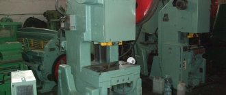
General view of the MA4129A forging hammer
Photo of forging hammer ma4129a
Photo of forging hammer ma4129a
Photo of forging hammer ma4129a. Back view
3-D model of a forging hammer ma4129a from the site asmcg-studio.ru
3-D model of a forging hammer ma4129a from the site asmcg-studio.ru
3-D model of a forging hammer ma4129a from the site asmcg-studio.ru
MA4129A Location of the components of the forging hammer
Location of the components of the hammer ma4129a
List of components of the MA4129A forging hammer:
- Bed - MA4129A-11-001SB
- Drive - MA4129-21-001SB
- Control - MA4129-41-001SB
- Fencing - MA4129-71-001SB
- Oil line - MA4129-81-001SB
- Electrical equipment - MA4129-91-001SB