What is idling of transformers, formulas and diagrams
An electric current transformer is an energy conversion device. The no-load current of the transformer characterizes losses in the absence of a connected load. The value of this parameter depends on several factors:
- Constructive design.
- Core material.
- Winding quality.
When manufacturing converters, they strive to reduce no-load losses as much as possible in order to increase efficiency, reduce heating, and also reduce the parasitic field of magnetic scattering.
What is no-load loss of a transformer
Any energy loss can lead to excessive consumption of materials and fuel, which leads to a significant increase in the cost of energy resources. To prevent losses from leading to serious financial costs, preventive and electrical measuring work must be periodically carried out on transformers, which allows timely identification of any problems and malfunctions in the operation of the equipment.
The most common cause of problems in the operation of transformers is no-load losses. Idling is one of the operating modes of the device, during which dedicated power is supplied to one winding of the device, while the remaining windings are open. No-load losses of a transformer are any leaks and losses that occur during this mode of operation of the equipment. Leaks necessarily occur at nominal levels of frequency, voltage and other parameters of electrical energy. No-load losses affect the quality of power supply, which should be kept in mind when creating electrical reconstruction projects in homes and other facilities.
An example of a draft technical report for non-residential premises
Back
Forward
General design and operating principle of the transformer
Structurally, the transformer consists of the following main parts:
- Closed core made of ferromagnetic material.
- Windings
The windings can be wound on a rigid frame or have a frameless design. Specially treated steel is used as the cores of industrial frequency voltage transformers. In some cases, there are devices without a core, but they are used only in the field of high-frequency circuitry and will not be considered within the framework of this topic.
The operating principle of the design in question is as follows:
- When the primary winding is connected to an alternating voltage source, it generates an alternating electromagnetic field.
- Under the influence of this field, a magnetic field is formed in the core.
- The magnetic field of the core, due to electromagnetic induction, creates an induced emf in all windings.
The induced emf is created, among other things, in the primary winding. Its direction is opposite to the connected voltage, so they cancel each other and the current through the winding when there is no load is zero. Accordingly, the power consumption when there is no load is zero.
Idle concept
The above reasoning is valid for an ideal transformer. Real designs have the following losses (disadvantages):
- core magnetization;
- core scattering magnetic field;
- electromagnetic dissipation of the winding;
- interturn capacitance of winding wires.
As a result, in real transformer designs, the induced induced emf differs from the rated voltage of the primary winding and is not able to fully compensate for it. Some no-load current occurs in the winding. When a load is connected, this value is summed with the rated current and characterizes the total losses in the electrical circuit.
Losses reduce the overall efficiency of the transformer, resulting in increased power consumption.
Measures to reduce no-load current
The main source of no-load current is the design of the magnetic circuit. In a ferromagnetic material placed in an alternating electric field, eddy currents of electromagnetic induction are induced - Foucault currents, which heat the core material.
To reduce eddy losses, the core material is made of thin plates separated from each other by an insulating layer, which is provided by an oxide film on the surface. The material itself is produced using a special technology in order to improve magnetic properties (increasing the value of magnetic saturation, magnetic permeability, reducing hysteresis losses).
The downside of using a large number of plates is that the magnetic flux breaks at the joints, resulting in a stray field. Therefore, for stacked cores, careful adjustment of the individual plates to each other is important. In strip split magnetic cores, individual parts are adjusted to each other by grinding, so when assembling the structure, parts of the core cannot be swapped.
O-shaped magnetic cores are free from these disadvantages. Their magnetic scattering field tends to zero.
The dissipation field of the winding and the interturn capacitance are reduced by changing the design of the windings and the spatial placement of their parts relative to each other.
Reducing losses is also achieved by filling the free window of the core as completely as possible. At the same time, the weight and dimensions of the device tend to be optimal.
How is the idle test performed?
The no-load experience involves applying voltage to the primary winding when there is no load. Using connected measuring instruments, the electrical parameters of the structure are measured.
To conduct the no-load experiment, the primary winding is connected to the network in series with a device for measuring current - an ammeter. A voltmeter is connected parallel to the terminals.
It should be borne in mind that the measurement limit of the voltmeter must correspond to the applied voltage, and when choosing an ammeter, it is necessary to take into account the approximate values of the measured value, which depend on the power of the transformer.
Transformation ratio
The transformation coefficient is most simply determined. To do this, the input and output voltages are compared. The calculation is made using the following formula:
This relationship is valid for all windings of the transformer.
Single-phase transformers
In single-phase transformers, the ammeter readings characterize the current consumed when there is no load. These readings are final and there is no need for further calculations.
Three-phase
To test a three-phase transformer, a more complex connection diagram is required. The following devices are required:
- ammeters for measuring current in each phase;
- voltmeters for measuring phase-to-phase voltages of the primary winding;
- voltmeters for measuring phase-to-phase voltages of the secondary winding.
When conducting an idle test, the following calculations are made:
- the average current value is calculated based on the ammeter readings;
- average voltage value of the primary and secondary windings.
The transformation ratio is calculated from the obtained voltage values similarly to a single-phase system.
Current measurement
When measuring current, you can only determine the amount of electrical losses. A more complex measurement scheme allows for a more complete determination of design parameters.
Application of a wattmeter
By connecting a wattmeter to the primary circuit, you can determine the power loss of the transformer in no-load mode. Summed up with the load power, the found value determines the overall power of the transformer.
Loss measurement
When measuring no-load current and power consumption, conclusions can be drawn about the total no-load losses, which lead to the following:
- Heating of winding wires.
- Core heating.
- Decrease in efficiency.
- The appearance of a magnetic scattering field.
Idling of three-phase device
The nature of the operation of the 3-phase device in XX mode depends on the magnetic system and the winding connection diagram:
- primary coil - “triangle”;
- secondary - “star” (D/Y): there is a free circuit of the TGC current I1 through the windings of the device. Therefore, the magnetic flux and EMF are sinusoidal and the unwanted processes described above do not occur; Y/D circuit: TGS magnetic flux appears, but the current from the additional EMF induced by it flows freely through the secondary coils closed in a “triangle”.
It will be interesting➡ Amazing facts about step-down transformers
This current creates its own magnetic induction vector flow, which extinguishes the third GS of the main MP that causes it. As a result, the magnetic flux and emf have an almost sinusoidal shape, the primary and secondary coils are connected in a star (Y/Y).
In the last TGS circuit, there is no current I1, since there is no path for it: the third harmonics of each phase at any time are directed towards the zero point or away from it. Because of this, the magnetic flux is distorted.
Further is determined by the magnetic system: A three-phase transformer in the form of a group of one-phase ones: the TGS of the magnetic flux is closed in each phase along its own core and, due to the low magnetic resistance of the latter, reaches an amplitude of 15% - 20% of the working magnetic flux.
It creates an additional EMF, the amplitude of which can already reach 45% - 60% of the main EMF. Such an increase in voltage can lead to insulation breakdown with subsequent breakdown of electrical installations. Transformers with an armored rod magnetic system have the same phenomena (the third harmonic magnetic flux is closed along the side yokes of the magnetic conductor).
Three-rod magnetic system: the TGS has no path along the magnetic core and is closed through a medium with low magnetic permeability - air, oil, tank walls. Therefore, it has a small value and does not induce significant additional EMF.
Equivalent circuit in transformer mode
Direct electrical calculation of a transformer is complicated because it consists of two electrical circuits connected by a magnetic circuit.
To simplify calculations, it is more convenient to use a simplified equivalent circuit. In the equivalent circuit, instead of windings, complex resistances are used:
- for the primary winding, the complex resistance is connected in series in the circuit;
- for the secondary winding parallel to the load.
Each complex resistance consists of a series-connected active resistance and inductance.
Active resistance is the resistance of the winding wires.
What does the magnetic flux of mutual induction in XX mode depend on?
The magnetic flux of mutual induction in a transformer depends on the method of placing the windings on the core and their design.
An important role is played by the fill factor of the magnetic circuit window, which shows the ratio of the total space to the space occupied by the winding.
The closer this coefficient is to unity, the higher the mutual inductance of the windings will be and the lower the losses in the transformer.
Transformer no-load detection
Transformers are complex equipment that is designed to change the current parameters in a circuit. They can increase or decrease the power and voltage of electricity in accordance with the requirements of consumers.
During operation, some power losses are detected in the equipment. Therefore, not all the electricity that enters the primary winding reaches the consumer. At the same time, the transformer (magnetic drive, windings and other parts) heats up. This indicator is not the same in different designs.
The no-load operation of the transformer makes it possible to determine current losses. This technique is used in combination with voltage determination in transformer short-circuit mode. This process is called aggregate experience. It is carried out according to a certain scheme.
- 1 General structure and types 1.1 Main types
- 1.2 Features of installations
- 2.1 Measurement approach
- 3.1 Single-phase devices
- 5.1 Using a wattmeter
Causes and consequences of transformer no-load losses
No-load losses in transformer devices of any type are a consequence of device wear. Over time, their magnetic system and the structure of the metal used ages and changes, the intersheet insulation becomes worse, and the core compaction weakens. Naturally, this negatively affects the level of electricity losses.
It will be interesting➡ What you need to know about current transformers
Practice shows that despite established standards, according to which losses can differ from factory indicators by no more than five percent, in many cases they exceed the threshold of fifty percent. This is especially true for power type transformers. Measurement data from this type of device makes it possible to fairly accurately predict energy losses in each individual municipality. The table of permissible losses during no-load operation of the transformer is given below.
Table of permissible losses during no-load operation of the transformer.
General structure and types
To understand what the no-load experience of various transformers is, it is necessary to consider what such equipment is.
Main types
Transformers are stationary machines that operate using electric current. They change the input voltage. There are several types of such devices:
- Power.
- Measuring.
- Separating.
- Coordinators.
Most often, a power transformer is required to be connected to the energy circuit. They may have two or more windings. The device can be single-phase (domestic network) or multi-phase (industrial network).
Features of installations
Autotransformers stand out separately. They have only one combined winding. There is also a welding machine. They have a specific scope of application.
Single-phase and multi-phase equipment may have different power ratings. It can be defined in the range from 10 to 1000 kVA or more. Low-power single-phase and multi-phase devices can be in the range of up to 10 kVA. Medium varieties will have a power of 20 kVA, 250 kVA, 400 kVA, 630 kVA, etc. If this figure is more than 1000 kVA, this is a high power unit.
Experiment methodology
The no-load losses of the transformer are determined when creating a certain mode. To do this, the current supply to all windings is stopped. They remain open. After this, the circuits are supplied with electricity. It is determined only on the first circuit. The equipment must operate under the voltage that is set by the manufacturer during its production.
Currents flow through the primary circuit of a power, welding or other installation, which are called XX. Their value is no more than 3-9% of the indicator specified by the manufacturer. In this case, there is no electricity on the secondary circuit winding. In the primary circuit, current produces magnetic flux. It crosses the turns of both windings. In this case, an EMF of self-induction occurs on the primary circuit and mutual induction on the secondary winding.
For example, the open-circuit voltage of a low- and medium-power welding transformer represents the mutual induction emf.
Measurement approach
Measuring no-load losses can be done in two aspects. They are called steel and copper losses. The second indicator indicates heat dissipation in the windings (they begin to heat up). During the experiment this figure is very small. Therefore they are neglected.
Data on the loss of no-load current of the transformer is presented in the form of a table. It calculates parameters for steel of certain grades and thickness. The no-load current of a transformer is considered in terms of power, which is created in the magnetic flux and is called steel loss. It is spent on heating sheets made of a special alloy. They are isolated from each other by a varnish coating. When creating such magnetic drives, the welding method is not used.
The essence of measurement
If for some reason the insulating layer between the plates of the magnetic drive is broken, eddy currents increase between them. At the same time, the system begins to heat up. The varnish layer is gradually destroyed. Losses during operation of the installation increase, its performance characteristics deteriorate.
In this case, power losses in steel increase . When calculating these characteristics in idle mode, it is possible to identify any disturbances in the operation of the unit. It is for this reason that the corresponding calculation is made.
Loss table
Active power consumption is the losses of the XX transformer. Part of it is spent on heating the winding wire (I1 2 * R1). It is insignificant, since the resistance R1 of the wire is negligible and the current XX is also small - 3-10% of the nominal.
The main share is spent on eddy currents in the magnetic circuit and its magnetization reversal. These phenomena lead to heating of the magnetic circuit. F1, which causes the bulk of no-load losses, does not depend on the load current. Consequently, losses exist constantly and in any mode of operation of the device, including active (load).
Loss table XX:
| Rated power, kVA | Rated voltage HV/LV, kV | No-load losses, W |
| 250 | 10/0,4 | 730 |
| 315 | 10/0,4 | 360 |
| 400 | 10/0,4 | 1000 |
| 500 | 10/0,4 | 1150 |
| 630 | 10/0,4 | 1400 |
| 800 | 10/0,4 | 1800 |
| 1000 | 10/0,4 | 1950 |
| 1250 | 10/0,4 | 2300 |
| 1600 | 10/0,4 | 2750 |
| 2000 | 10/0,4 | 3200 |
| 2500 | 10/0,4 | 4200 |
Over time, losses increase due to the following changes in the magnetic circuit:
- the structure of steel changes;
- the insulation resistance between the plates drops;
- The insulation of the ties is broken, which leads to a short circuit between the plates.
Transformation ratio
When determining the operation of an installation, a concept such as transformation ratio is used. Its formula is presented below:
It follows that the voltage on the secondary circuit will be determined by the ratio of the number of turns. To be able to regulate the output electricity, a special device is built into the design of the installation. It switches the number of turns on the primary circuit. This is an antsapf.
To conduct the experiment at idle, the regulator is placed in the middle position. In this case, the coefficient is measured.
Single-phase devices
To carry out the presented experiment, when using a step-down or step-up household unit, the presented coefficient is taken into account. In this case, two voltmeters are used. The first device is connected to the primary winding. Accordingly, the second voltmeter is connected to the secondary circuit.
The input impedance of the measuring instruments must correspond to the nominal characteristics of the installation. It can operate in buck or boost mode. Therefore, if it is necessary to carry out repair work, not only the supply of low but also high voltage is measured on it.
Three-phase devices
For three-phase units, during the experiment, indicators on all circuits are examined. In this case, you will need to use 6 voltmeters at once. You can use one device that will be connected in turn to all measurement points.
If the value set by the manufacturer on the primary winding exceeds 6 kV, a current of 380 V is supplied to it. When measuring in high-voltage mode, it is impossible to determine indicators with the required accuracy class. Therefore, measurements are carried out in low voltage mode. It is safe.
Applying the coefficient
During the measurement process, the trunnion is moved to all positions specified by the manufacturer. In this case, the transformation coefficient is measured. This allows you to determine the presence of a short circuit in the turns.
If the phase readings have a scatter during measurements of more than 2%, as well as their decrease in comparison with previous data, this indicates deviations in the operation of the unit. In the first case, a short circuit is detected in the system, and in the second, a violation of the insulation of the windings is detected. The unit may not operate correctly.
Such facts require confirmation. For example, this could be a resistance measurement. An increase in the spread of the coefficient indicators can be influenced by an increase in the resistance between the contacts of the axle. When switching frequently, this situation occurs.
How to determine the transformation ratio
What is “transformer no-load”? In fact, this is a special mode of operation of the device, the condition of which is that the secondary winding is open, and the primary winding has a rated voltage. In this state, when carrying out a series of calculations, it is possible to determine the exact parameters of a number of indicators, for example, for transformer devices of the common single-phase type, the following are calculated:
- transformation ratio;
- active, total, inductive resistance of the magnetization branch;
- power factor, percentage current and no-load measurements.
Material on the topic: how a toroidal transformer works and what are its advantages.
The algorithm for measuring idle speed looks like this:
- The current that was applied to the primary winding is measured using measuring instruments that are included in the common circuit.
- The secondary winding on the voltmeter closes. The resistance should be of such a value that the value of the secondary winding current approaches the minimum mark.
- The amount of no-load current in the primary winding is minimal relative to the nominal value when compared with the applied voltage, which is balanced by the electromotive force of the primary winding. And both of these indicators differ slightly, which means the value of the course of the electromotive force in the primary winding can be determined from the data of a voltmeter.
Most accurate
The desired values can be obtained using windings of different voltages - low and high. The accuracy of such measurements will be determined by the difference in denominations between
mi.
Electricity loss diagram.
Loss measurement
Losses in the magnetic drive are measured exclusively when using a powerful installation. In this case, you can take for calculations a reduced voltage, which is connected to the primary circuit through a wattmeter. This is a direct measurement method.
When taking into account the readings of a voltmeter or ammeter, you will need to multiply their powers by each other. This is an indirect method. However, the result has a certain error. The distortion occurs due to the inability to take into account the power factor in such a calculation. This is the cone angle that is formed in a vector circuit between voltage and current. In idle mode, an angle of 90º appears between them.
Application of a wattmeter
The wattmeter allows you to measure taking into account the power factor. This makes it possible to obtain a more accurate result. The calculation is performed using the following formula:
Next, you need to create a vector diagram based on the obtained result. For each phase, established losses are taken into account. For this purpose, a table is most often built. In this case, the scheme that was originally used by the manufacturer when creating the equipment is used.
The obtained result cannot be compared with the standards. The indicators are compared only with the characteristics of previous inspections. If losses only increase over time, this indicates a violation of the insulation of the magnetic drive plates or the appearance of other violations. It is impossible to reverse this process.
Carrying out idle speed measurements allows you to assess the condition of the equipment, as well as determine the need for scheduled or emergency repairs. Therefore, regular tests allow you to correctly plan the operation of the installation and prevent its unexpected shutdown.
Interesting video: Description of the basics of a transformer.
Source
Measurement of current and no-load losses
In accordance with the requirements of the PUE, one of the measurements is made: a) at rated voltage. The no-load current is measured. The current value is not standardized;
Rice. 2.7. Scheme for checking the connection group of the windings of a power transformer using the phase meter method.
Rice. 2.8. Schemes for checking the connection group of windings of power transformers using the two-voltmeter method.
b) at low voltage. The measurement is carried out with or without reduction of losses to the rated voltage (comparison method). The no-load experience of a transformer is the switching on of one of its windings (usually low voltage) to the rated voltage. The current consumed in this case is called the no-load current Iхх (usually expressed as a % of Ir).
Table 2.10. Vector diagrams and calculation formulas for determining the connection group of power transformers
Note : Formulas table. 2.10
where U2 > and Cl are, respectively, the linear voltage at the terminals of the low voltage winding and the linear transformation ratio.
The active power consumed in this case is called no-load losses Рхх (kW). This power is spent mainly on magnetization reversal of electrical steel (hysteresis losses) and eddy currents. Current and no-load losses are the rating data of power transformers.
The no-load losses of transformers Рхх, measured at normal frequency and very low excitation (of the order of several percent of the rated voltage of the transformer), can be converted to no-load losses at rated voltage using the formula
where P'xx= Riz – Ppr losses measured at the voltage (excitation) U supplied during measurement; Rpr and Riz are, respectively, the power consumed by the devices and the total losses in the transformer and devices. n is the exponent equal to 1.8 for hot-rolled steel; for cold-rolled steel - 1.9.
Manufacturers measure no-load losses at rated voltage and at low (usually 380 V) voltage.
No-load losses can also be measured at a voltage equal to 5 - 10% of the nominal voltage. The difference between the obtained loss values and the factory data should be no more than 10% for single-phase and no more than 5% for three-phase.
No-load losses are measured at voltages and according to the circuits specified in the manufacturer's test report.
If the manufacturer measured no-load losses only at the rated voltage of the transformer, then the no-load losses should be measured at a voltage of 380 V and recalculated to the rated voltage using the formula indicated above.
In the future, measurement of no-load losses should be carried out at voltages of 380 V. For serviceable three-phase three-core transformers, the loss ratio, as a rule, does not differ from the ratios obtained at the manufacturer by more than 5%.
For transformers that have a switching device with a current-limiting reactor, an additional no-load test is performed in the intermediate “Bridge” position.
Measuring no-load losses at a voltage of 380 V should be carried out before measuring the resistance of the windings to direct current and warming up the transformer with direct current.
When measuring losses and no-load current, measuring instruments of accuracy class 0.5 should be used. For measurements, portable measuring kits of the K-50 (K-51) type can be used.
When measuring losses and no-load current at rated winding voltages above 0.4 kV, it is recommended to use measuring transformers of accuracy class 0.2.
No-load losses of three-phase three-leg transformers are measured under three-phase or single-phase excitation.
With three-phase excitation, measurements are made with two single-phase wattmeters or one three-phase wattmeter (see Fig. 2.9).
The measured loss is defined as the algebraic sum of the losses measured by each wattmeter. Losses in a transformer are defined as the difference between the measured total losses and losses in devices (see Fig. 2.10), since losses in devices can be comparable to no-load losses.
Rice. 2.9. Schemes for switching on devices when conducting no-load testing of power transformers. a - for single-phase transformers; b - for three-phase transformers.
The no-load current of the transformer is determined as the arithmetic mean value of the currents of the three phases.
When measuring no-load losses with single-phase excitation with a voltage of 380 V, three experiments are carried out with bringing a three-phase transformer to a single-phase one by alternately short-circuiting one of its phases and excitation of the other two phases.
The first experiment is to short-circuit the winding of phase A, excite phases B and C of the transformer and measure the losses. The second experiment is to short-circuit the winding of phase B, excite phases A and C of the transformer and measure the losses.
Causes of idle losses
Today, oil and dry transformer devices are used. Until recently, oil transformers were more common, but they have a number of serious disadvantages, for example, low fire safety and difficulty in placement, which is why today dry transformers are used much more often.
Among the main reasons for idle losses in various devices are the following factors:
- Corrosion processes on metal elements of transformers. Corrosion on metal occurs due to damage to the protective varnish layer, which causes eddy currents to increase on the equipment and significant heating of the metal plates.
- Turning short circuits on the windings, which can cause strong voltage surges.
- Low quality insulation.
- Magnetic gaps on metal elements.
- Too many or too few winding turns.
- Overheating of elements of transformer equipment.
These are just the most basic causes of idle losses that experts encounter most often. There are other factors due to which the amount of no-load losses may exceed acceptable limits, which will increase the cost of operating electrical systems. To determine the causes of losses on an individual transformer, the owner will need to order the services of professional electrical measurements.
Below you can use the online calculator to calculate the cost of electrical laboratory services.
What is no-load speed (XX) of a transformer?
The amount of power transformer losses consists of the so-called copper losses and steel losses. The first are associated with the flow of load current through the winding conductors, which have a certain electrical resistance. Losses in steel are caused by eddy currents and magnetization currents arising in the magnetic circuit.
Therefore, this experiment allows us to measure the power losses in steel, called no-load losses.
Additionally, by connecting a voltmeter to the remaining open winding, you can measure the voltage on it and, based on the readings of two voltmeters, calculate the transformation ratio. But this measurement does not apply to the idling experience itself.
Idling experience during commissioning is subjected to
- All dry transformers, as well as those having a liquid non-flammable dielectric as an insulating and cooling medium.
- Oil-filled transformers with a power of more than 1600 kVA.
- Transformers for auxiliary needs of power plants, regardless of their power.
In operation, such measurements are carried out only for transformers with a power of 1000 kVA or more, and only after major repairs associated with changing the windings or repairing the magnetic circuit.
According to network rules, it is possible to carry out measurements by order of the technical manager of the enterprise after chromatographic analysis of gases dissolved in oil has given alarming results. But this applies only to power transformers with windings for voltages of 110 kV and higher.
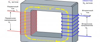
Transformer no-load mode
Idle circuit (XX) is the connection of a device when the rated alternating voltage is supplied to the primary winding, and the circuits of all secondary windings are open (no loads are connected).
In a voltage converter, the division of windings (coils) into primary and secondary is conditional. Any of them becomes primary when the original alternating voltage is applied to it. Others, in which EMF is induced, become, accordingly, secondary.
The idle test is carried out according to the scheme shown in the figure.
Consequently, any transformer, depending on the connection method, can be either a step-down or step-up transformer (except for an isolation transformer - with a transformation ratio equal to unity).
Since the secondary coil circuit is disconnected, there is no current in it (I2 = 0). I1 flows in the primary, forming the flux of the magnetic induction vector F1 in the magnetic circuit. The latter changes according to a sinusoidal law, but due to the magnetization reversal of the steel, it lags in phase from I1 by angle B (loss angle).
The following terminology applies:
- I1: transformer current XX;
- F1: working magnetic flux.
Under the influence of F1, an EMF arises in all coils:
- in primary – self-induction (E1);
- in secondary ones – mutual induction (E2).
The dependence of EMF on various parameters is determined by the formulas:
E1 = 4.44 * f * W1 * Ф1max *10 -8,
E2 = 4.44 * f * W2 * Ф1max * 10 -8, where
W1 and W2 - number of turns in the windings;
Ф1max is the magnitude of the magnetic flux at the maximum point.
Consequently, the numerical value of the EMF is directly dependent on the number of turns of the coil. From the ratio of the EMF in the primary and secondary windings, the main parameter of the device is determined - the transformation ratio (K): K = E1 / E2 = W1 / W2.
Compared to the primary coil, the secondary coil contains:
- in a step-up transformer – more (K is less than one);
- in the downward direction it is less (K is greater than one).
In addition to the working (main) magnetic flux Fr1 is formed in the installation. These are power lines that branch off from the working magnetic flux F1 in the core and close through the air around the turns of the coils. Like F1, Fr1 is variable, which means that, according to the law of electromagnetic induction, it induces self-inductive emf Ep1 in the primary winding.
E1 and Ep1 are always directed opposite the voltage U1 applied to the primary winding. By the nature of their effect on current, they are similar to a resistor, which is why they are designated by the term “inductive reactance” (X).
Capacitive and inductive reactance
Consequently, creating I1, the voltage U1 overcomes the active resistance R1 of the primary coil and both self-induction emfs. Mathematically it looks like this: U1 = I1 * R1 + (-E1) + (-Ep1).
The recording is made in vector form, therefore, the symbols “-” are placed before the designations of the self-induction EMF: they indicate the opposite direction of these vectors relative to the voltage U1. The no-load current I1 is not strictly sinusoidal.
It is distorted because it contains the so-called third harmonic component (THC), caused by eddy currents, hysteresis and magnetic saturation of the magnetic circuit. But with a certain degree of approximation, suitable for practical calculations, it can be replaced by an equivalent sinusoidal current with an equivalent effective value.
Measurement procedure and scheme
Before carrying out the experiment, the process of demagnetization of the magnetic circuit of the transformer under test is carried out. This is done using a direct current passed through one of the low voltage side windings. The current connection is made repeatedly, each subsequent connection occurs with a change in polarity and a decrease in value.
The initial value should not be less than twice the expected no-load current. With each subsequent switching on, the value decreases by 30-40%. The process ends at a current less than the no-load current.
To carry out measurements, you will need three laboratory instruments with an accuracy class of at least 0.5. These are ammeters, voltmeters and wattmeters. ammeters are connected to each phase in series. voltmeters are switched on to the linear voltage of all three phases. The current windings of wattmeters are connected in series with ammeters.
The voltage windings of the wattmeters are connected according to the diagrams given. Voltage is applied and readings are taken from the instruments.
Strictly speaking, the measurement is carried out according to the same schemes that were used at the manufacturer to conduct the experiment. After all, the data obtained will need to be compared with the factory data. But, if a three-phase voltage source is not available, three measurements can be made by applying voltage to two phases of the transformer winding, short-circuiting the third, which remains free.
In this case, only linear voltage is used, since distortion of the curve shape due to nonlinear loads in the network has minimal influence on it. Using the same schemes, an idle test is carried out at a reduced (low) voltage.
Who needs energy efficient transformers
The Transformer group's product range includes a whole line of energy-efficient transformers.
How do they achieve efficiency and how much are losses reduced? A transformer, like any device, requires energy to operate. Part of it is spent on heating the wires in the windings - these are short circuit losses (Psc), part is spent on magnetization reversal processes in the core - these are no-load losses (Pxx). Due to changes in load during the day and at different periods of the year, the weight of a unit of no-load losses is two to four times higher than short-circuit losses. Therefore, energy-saving transformers are characterized primarily by reduced no-load losses.
In order to assess energy efficiency, we compare various Transformer transformers with a power of 1000 kVA: for an oil sealed transformer (TMG) in the standard version, Pxx = 1600 W, for its analogue with reduced losses (TMG12 series) Pxx = 1100 W. The losses for dry transformers with cast insulation “Transformer” are also different: for TSL in the standard version Pхх = 2000 W, for TSL low-noise with reduced losses Pхх = 1500 W. This means that, compared to a standard transformer, an economical transformer consumes 500 W less for each hour of operation. Over a year of operation, it will save 4380 kW only due to reduced Rxx. At a tariff of 3 rubles per kilowatt, the savings in monetary terms will be 13,140 rubles.
Technologically, reducing no-load losses is achieved by assembling a magnetic core using step-lap technology and using higher grade electrical steel. The use of amorphous steel gives an even greater effect. No-load losses in the ATMG transformer (oil sealed transformer with an amorphous core, manufactured by Transformer) with a power of 1000 kVA are only 450 W. The operation of such a transformer saves 10,074 kW annually. It is not difficult to imagine how much electricity will be saved if hundreds of thousands of power transformers operating in the country are replaced with energy-efficient ones.
Power transformers with reduced losses were developed primarily for the country's electric grid companies - in power systems, 25-30 percent of technical losses occur in distribution transformers. Back in 2008, it launched a whole line of economical TMG transformers. And this year, the first samples of innovative “amorphous” ATMG transformers were manufactured for trial operation in the networks of IDGC Holding.
It is worth noting that losses can be reduced not only by using energy-saving installations. One of the possible technologies is changing the network topology and reducing the length of lines on the 0.4 kV side. To implement this approach, instead of one large transformer-distribution substation, several pole-type transformers are installed. They are located near small groups of end consumers and ensure their connection to the 6-10 kV network with voltage reduction to 0.4 kV. This solution can be used to connect individual subscribers - farms, holiday communities, cottage villages, etc. If you install transformers with reduced losses, then energy consumption will be even more efficient.
Due to higher production costs, the cost of a transformer with improved characteristics and an “amorphous” power transformer, of course, will be slightly higher than the price of a standard analogue. But due to lower electricity costs, this increase will pay for itself after three to five years of operation, depending on the power of the transformer and regional electricity tariffs, and the overall economic effect will be positive. On a national scale, the use of energy-saving transformers will save tens of billions of rubles annually.