Materials, markings, sizes
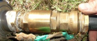
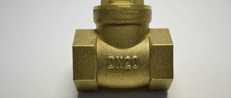
The check valve for water is made of stainless steel, brass, larger sizes are made of cast iron. For household networks, brass is usually used - it is not too expensive and durable. Stainless steel is, of course, better, but it is usually not the body that fails, but the locking element. This is where you should approach your choice carefully.
For plastic plumbing systems, check valves are made from the same material. They come in polypropylene and plastic (for HDPE and LDPE). The latter can be welded/glued or threaded. You can, of course, solder adapters to brass, install a brass valve, then again an adapter from brass to PPR or plastic. But such a unit is more expensive. And the more connection points, the lower the reliability of the system.
For plastic and polypropylene systems there are check valves made of the same material
The material of the locking element is brass, stainless steel or plastic. Here, by the way, it’s hard to say which is better. Steel and brass are more durable, but if a grain of sand gets between the edge of the disk and the body, the valve jams and it is not always possible to return it to functionality. Plastic wears out faster, but it doesn’t jam. In this regard, it is more reliable. It’s not for nothing that some manufacturers of pumping stations install check valves with plastic discs. And as a rule, everything works for 5-8 years without failures. Then the check valve begins to “poison” and is replaced.
What is indicated in the labeling
A few words about the marking of the check valve. It states:
- Type
- Conditional pass
- Conditional pressure
- GOST according to which it is manufactured. For Russia, this is GOST 27477-87, but there are not only domestic products on the market.
The conditional diameter is designated as DU or DN. When choosing this parameter, you need to focus on other fittings or pipeline diameter. They must match. For example, you will install a check water valve after a submersible pump, and a filter next to it. All three components must have the same nominal diameter. For example, all should have DN 32 or DN 32 written on them.
A few words about conditional pressure. This is the pressure in the system at which the shut-off valves remain operational. You should definitely take it no less than your working pressure. In the case of apartments - no less testing. According to the standard, it exceeds the working one by 50%, and in real conditions it can be much higher. You can find out the pressure for your home from the management company or plumbers.
What else to pay attention to
Each product must come with a passport or description. It indicates the temperature of the working environment. Not all valves can work with hot water or in a heating system. In addition, it is indicated in what position they can work. Some should only stand horizontally, others only vertically. There are also universal ones, for example, disk ones. That's why they are popular.
Opening pressure characterizes the “sensitivity” of the valve. For private networks it rarely matters. Only on supply lines close to the critical length.
Also pay attention to the connecting thread - it can be internal or external. Choose based on ease of installation
Don't forget about the arrow that indicates the direction of water movement.
Dimensions of check valves for water
The size of a check valve for water is calculated according to the nominal diameter and they are produced for all - even the smallest or largest pipeline diameters. The smallest is DN 10 (10 mm nominal bore), the largest is DN 400. They are the same sizes as all other shut-off valves: taps, valves, drains, etc. Conditional pressure can also be referred to as “dimensions”. The lowest is 0.25 MPa, the highest is 250 MPa.
Each company produces check valves for water in several sizes.
This does not mean that any of the valves will be in any variant. The most popular sizes are up to DN 40. Next come the main ones, and they are usually purchased by enterprises. You won't find them in retail stores.
And also, please note that for different companies, with the same nominal diameter, the external dimensions of the device may differ. The length is clear
Here the chamber in which the locking plate is located may be larger or smaller. The diameters of the chambers also differ. But the difference in the area of the connecting thread can only be due to the thickness of the walls. For private houses this is not so scary. Here the maximum working pressure is 4-6 Atm. But for high-rise buildings it can be critical.
How to check
The easiest way to test a check valve is to blow into it in the direction that is blocking it. No air should pass through. At all. No way. Also try pressing on the plate. The rod should move smoothly. No clicks, friction, distortions.
How to test a check valve: blow into it and check for smoothness
Valve operation.
Operation comes down to periodic cleaning of the nylon filter. About once every month or two, the filter should be washed in soap and water.
The valve of the latest modification, since the last revision, has been in operation for more than 11 years and was dismantled for the purpose of photographing this article. I hope that I will live to see the next revision.
The question may arise as to how to find out in what position the valve flaps are located, since they are not visible from the room.
If you sharply open the door of the room in which the valve is installed, and the valve makes a bang, then its flaps are open; if the valve slams when the door is closed, then the flaps are closed. But, this is if the door opens to the outside of the room. If the door opens inward, then everything will be exactly the opposite.
Purpose of the device
The need for installation is explained by the fact that a modern apartment is a completely sealed room due to the fact that PVC windows do not allow air flow when closed. Opening them for ventilation is not always convenient, since in winter too much cold air enters.
In this regard, several difficulties arise at once:
- excess exhaled carbon dioxide accumulates in the room;
- chronic lack of oxygen leads to stuffiness, stuffy air and often heaviness in the head;
- moisture quickly accumulates in a confined space; systematic over-humidification of the air leads to the formation of mold on walls and products.
A supply valve mounted into the wall is convenient in that it creates a uniform and constant weak inflow, which essentially replaces the need to use a window during the cold period.
The valve is designed for use in any residential or commercial premises. Its use is especially relevant:
- if there are many people living in the apartment, especially small children;
- if there are often a lot of people in the room;
- if the apartment has pets and/or plants that constantly need fresh air.
The need for additional ventilation increases if the house is old, since in this case the natural ventilation system, which was installed during construction, most likely does not function or does not work effectively enough.
Ventilation in an apartment or house
Air exchange in an apartment or house, on the one hand, must comply with the standards established for residential buildings, and on the other hand, it is subject to the laws of physics. Therefore, it is not always possible to get by with trivial solutions and sometimes you have to install a check valve designed to allow flow in one specific direction.
Standards and regulations
The main document that you need to rely on when designing ventilation both in an apartment and in a private house is SP 54.13330.2016. This is an updated version of SNiP 01/31/2003 “Residential multi-apartment buildings”. The air movement diagram for a residential building of any layout must be drawn up based on the provisions of paragraphs. 9.6 and 9.7 of this set of rules.
Table 9.1 establishes air exchange standards for various types of premises. Designers and owners of commercial real estate are required to strictly follow these parameters.
The influx of outdoor air should occur in living rooms and the kitchen, and the outflow should occur from the kitchen, bathroom and technical rooms
Residents can install ventilation with a lower capacity, focusing on microclimate indicators:
- Humidity, which can be measured with a hygrometer. Air oversaturated with water leads to the formation of fungus on the wallpaper and ceiling, as well as stains on the windows.
- Carbon dioxide, the concentration of which can be measured by a gas analyzer. Without the device, the lack of oxygen can be clearly felt immediately upon entering the room from the street.
Air circulation can be natural or forced. This depends on many factors, including area, number of floors, location of rooms and technical premises.
The ventilation system of the gas boiler room is autonomous. Due to safety requirements, it cannot be combined in any way with the air circulation inside the house
Thus, in any housing there are points of air inflow and removal, and a situation where an outflow occurs through the inlet opening and an air mass enters through the ventilation shaft is unacceptable.
This leads to violation of sanitary, hygienic, fire safety and other standards and can seriously worsen living conditions.
Artificial and natural air exchange
Sometimes a situation arises when it is necessary to forcefully remove air from the following rooms:
- Kitchen. When cooking food, intense evaporation may occur. To prevent it from spreading throughout the kitchen and further into other rooms, a hood is installed above the stove. Its operation allows you to direct contaminated air directly into the ventilation shaft.
- Bathroom. When taking a shower, the air becomes saturated with water vapor. To quickly remove it, turn on the ventilation unit, since otherwise the appearance of mold or peeling of plastic and tiles will occur much more intensely.
- Workshop. During carpentry or other work, a suspension is often formed that can be harmful to human health. To do this, run fans or hoods that are located near the source of pollution.
Turning on forced ventilation is temporary, as it consumes a lot of electricity and creates noise during operation.
A powerful hood is capable of taking all the air above the stove, but when turned off it does not allow any air into the ventilation duct.
After the introduction of devices for forced ventilation, a problem arises with the natural circulation of air through the obstacle that has arisen. If an ordinary bladed fan somehow still allows air flow to pass through, then hoods, as a rule, minimize the passage to unacceptably low levels.
Stopping natural circulation can cause local problems in the room. For example, in the kitchen there will be increased humidity and in winter the windows will leak. But what's even worse is that air movement throughout the house will be disrupted, which will affect all rooms.
Installing a hood can have another negative consequence if this device is integrated into the general duct ventilation. Air exchange is subject to the law of maintaining balance: at any given time, the amount of incoming and outgoing air is the same.
It follows from this that an increase in pressure at one point leads to a change in readings at others. The main thing here is to exclude the possibility of flow reversal.
An increase in air flow power leads to a redistribution of pressure inside the duct ventilation. In the absence of check valves, reverse may occur
To solve both problems, install a check valve. Taking into account the fact that modern air ducts for residential premises have standard dimensions, independent installation of such an element is not very difficult.
Making and installing a check valve yourself
Although the market offers a large selection of types of devices to solve certain problems, some people decide to make the valve themselves. To do this, you will need to purchase individual elements of the future product and fastening means.
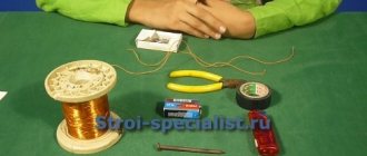
Required tools and materials
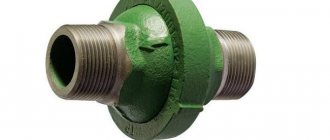
To make your own ball-type shut-off valves for water, you need to prepare the necessary materials in advance:
- Tee with internal thread.
- For the valve seat, you need to take a coupling with an external thread.
- Spring made of stainless steel. It should fit into the hole freely.
- Cork. It will serve as a plug for the entire device and support for the spring.
- A steel ball, the diameter of which is slightly less than the nominal diameter of the tee.
- FUM tape.
Work progress
When all the materials are ready, you can begin the process of assembling the product. To do this, you can use the instructions below:
- First of all, screw the coupling into the tee, which will serve as a saddle for the valve element. It is necessary to screw in until the coupling covers the side hole of the tee by approximately 2 mm. This is necessary so that the ball does not jump out into the side passage.
- Through the opposite hole, a ball is first inserted, and then a spring.
- Plug the hole through which the spring was inserted. This is done using a threaded plug using sealing tape.
- Such a homemade device will allow water to flow into the side hole due to the fact that the direct flow will put pressure on the ball and the spring, and in the absence of flow, the ball will block the passage, returning to its original position under the action of the spring.
When making the device yourself, it is recommended to correctly adjust the spring. It should not deviate when the pressure in the system is low, and should not be too tight so as not to interfere with the normal flow of fluid.
Rules for installation and operation of the device
There are a number of rules and recommendations that must be followed when carrying out installation work:
- Using a valve, turn off the water supply completely or only at the installation site.
- Devices in which the operating element comes to the closed position due to gravity should be mounted in a horizontal position. On vertical pipelines, such devices will only work if water moves through the pipeline from bottom to top. All other types of valves can be fixed to both horizontal and vertical pipes.
- The arrow on the device body must coincide with the direction of water movement.
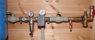
- It is recommended to install a mesh filter in front of the device, which will trap debris present in the liquid.
- In order to be able to diagnose the condition of the device in the future, a pressure gauge can be attached to the outlet of the device.
- It is not recommended to destroy the paint coating on the device body, as it performs a protective function.
Connection diagram
In heating and water supply systems, the choice of location for installing the valve is determined by those areas where water or coolant flow is required in only one direction, and the hydraulic features of the system can lead to fluid flow in the opposite direction. These shut-off valves should be installed in accordance with all regulatory requirements. The following connection diagrams exist:
- If the system contains several pumps installed in parallel to each other, then the valve should be mounted on the connecting pipe of each pump. This is done to prevent water from flowing in the opposite direction through a failed pump.
- If heat flow sensors or water consumption meters are installed in the system, then a valve should be installed on their pipes. The absence of a shutter can cause water to flow in the opposite direction through the meters, which will lead to improper operation of these meters and incorrect readings.
- In heating systems with a common heat supply center, the device must be installed in the mixing units on the jumper. If this is not done, the coolant may pass from the supply pipe to the return pipe, bypassing the heating system.
- In a heating system, the valve is installed in the area through which the coolant flows from the heating device to the heating device, if there is a possibility of a pressure drop in this area. This will help prevent the backflow of water from the pipeline when the pressure in the external network drops. In this case, on the return section it is necessary to install a pressure reducer that operates on the “toward” principle.
Connection diagram.
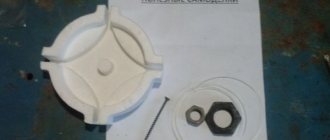
Manufacturing of valve flaps.
Particular attention should be paid to the polyethylene film from which the valve flaps are made. I used 0.1mm thick polyethylene. The larger the cells in the valve body, the thicker the film should be.
It is better to go to the market to buy film with your own scissors. You also need to choose the largest roll with a smooth film. Wavy film is not suitable. You need to cut several pieces of film directly from the roll and immediately put them in a hard folder for papers so that the film does not accidentally wrinkle.
To attach the flaps to the valve body, I used Mylar tape. Previously, similar tape was used for gluing tape tape.
The video shows the process of making valve flaps. Expand the player to full screen to see the video in HD quality.
The sashes are made in the following order.
First, a piece of film of the required size is glued to the base using adhesive tape (scotch tape).
Then, using a sharp knife, the outline of the valve flaps is cut along a ruler. And only at the very end the valve flaps are separated from each other.
If the film accidentally becomes wrinkled during gluing or assembly, you can safely change it. With low excess pressure in the ventilation shaft, the crumpled film will “siphon” and let miasma into the apartment.
To seal the joint between the valve and the wall of the room, it is convenient to use a self-adhesive sealing tube. I bought a meter of pipe at the construction market, which is usually used to seal windows and doors.
Ventilation devices with built-in check valves
An anti-return valve can be an integral part of many devices for natural and forced ventilation. Let's look at a few examples.
Exhaust fans with check valve
New models of exhaust fans with a check valve can operate almost silently thanks to the design features using liners that dampen vibration. The small bearings of the device are treated with “eternal” lubrication, which does not require periodic renewal. All parts of the case are made of strong, durable plastic that is resistant to high temperatures and humidity. The minimum warranty period for exhaust fans with a check valve is three years.
Fan device diagram
Three types of valves can be installed in fans:
- with manual or automatic control;
- on springs;
- mechanical (changing the direction of the petals based on air pressure).
The most common devices are spring-based. Springs return the blade flaps to the closed state as soon as the fan stops operating.
When choosing a fan, pay attention to the size of the ventilation outlet. What you should pay attention to when purchasing a device:
What you should pay attention to when purchasing a device:
- fan power;
- check valve shape;
- noise level;
- energy consumption level;
- decor.
For exhaust hood in the bathroom, a power factor of 6 is used - that is, the atmosphere in the room must be updated 6 times per hour
Fans can be overhead or in-duct. In-channel ones are inserted into the hole in the air shaft. The further you install the device into the shaft, the lower the noise level in the room will be. For small shafts, overhead models are used; they are mounted on the wall near the ventilation hole.
The exhaust fan can be equipped with a timer and a motion sensor. This is very convenient; there is no need to control the device using a switch.
Ventilation grille with check valve: design and purpose
This is a very simple design, consisting of a decorative grille, a flange and the petal itself. Ventilation grilles with valves can be round, rectangular or square. For household purposes, these products are made of durable plastic.
In addition to blocking incoming air flows, such devices are equipped with mosquito nets to protect against insects and noise-absorbing pads.
Ventilation devices of this type are most often used in private houses, where the entire ventilation system is combined at one point on the roof and the air in it is forcibly pumped out using a small electric motor. In this case, such grilles are installed in every room of the house.
Tees with check valve and their application
Ventilation tees with a check valve are used both as a stand-alone device for ventilation and in conjunction with a hood. They are not used very often; there is an opinion that for natural ventilation it is enough to simply install a conventional anti-return device.
This is what a tee for ventilation looks like
Exhaust tees with a check valve are often used when connecting a solid fuel boiler. Such a device not only ensures the release of combustion products into the exhaust pipe, but also refreshes the air in the room.
Using a check valve on an exhaust hood
Returning to the topic of ventilation in kitchens, let's talk again about what is an anti-return valve for an exhaust hood? We have already written about the design of this device, but how to install it and use it correctly?
There are two options: without a tee or with a tee.
In the first case, two grilles are inserted into the ventilation hole, suitable for connecting a corrugated hose. An exhaust hood is connected to one of the grilles, and an anti-return structure is connected to the second. When the hood is turned on, the valve will prevent air from the ventilation from entering the room. And when the hood is turned off, natural air exchange will work.
This method will allow you to use not only a corrugated hose to connect a kitchen umbrella, but also a rectangular ventilation duct, which has excellent aerodynamic properties and an attractive design
The second option for connecting a check valve for an exhaust hood involves using a tee already known to you. One outlet of the tee is directed to the ventilation shaft. The second is connected to the corrugated hose of the hood, and an anti-return device is mounted on the third outlet. This hood with a check valve works in the same way as the first one, only it looks different.
Hood with tee
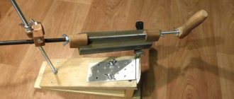
Valve installation.
To install the valve, I drilled four holes with a diameter of 8 mm in the wall and hammered factory nylon plugs (dowels) into them. The valve body was secured with four screws and washers, having previously placed rubber gaskets under the washers.
To avoid damaging the valve flaps during installation, I pressed them down with a piece of cardboard and removed the cardboard only when the valve was secured to the wall with the two top screws.
The right side of the valve is not visible in the photo, since the vent hole is located just behind the cast iron sewer pipe.
Since the fan was purchased with some power reserve, I connected it to the network through the simplest triac regulator. The regulator allows you to reduce the engine speed and, accordingly, reduce noise. The design of this homemade power regulator is described in detail here.
How to Design a Check Valve
To build a check valve, you will need to buy a grille, polymer film and fasteners. It is also better to purchase a sealant to create the device. The simplest design option is a membrane-acting valve. It is easy to construct it with your own hands.
The design is protected from condensation on the front panel of the supply air regulator. It has an automatic pressure-throttle system for excess supply air. The amount and direction of fresh air flow is determined by the front panel, which has a mechanism for changing the opening angle. The front grille opens at the top edge and directs the air flow up and down to ensure comfortable air distribution even when used in underfloor heating. The filter is mounted in a cylindrical filter basket and is additionally protected from water interference.
The manufacture of a check valve is carried out in the following sequence:
- Measure the dimensions of the ventilation hole, and then cut out the grille. It should have dimensions exceeding the dimensions of the vent by 2 cm.
- If there is plastic for the workpiece, the grate can be made using a file.
- Its surface should be smooth. This will ensure a tight fit of the membranes.
- Secure 2 squares of film on 2 sides of the grille. This procedure is performed using sealant.
- Use a drill to make holes in the grille - the fasteners will subsequently be placed in them.
- Place the grate in the vent and screw it on.
Such a device will work effectively both in the case of natural and forced ventilation. It will be especially useful to install a check valve if there are some problems with ventilation. This will allow you to maintain fresh air in the room, eliminating the appearance of unpleasant odors.
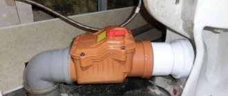
The valve is equipped with a damping tube designed for direct wall mounting. Every sewer system must have a vented and vented portion. Unpleasant and unsafe odors emanating from sanitary ware, drain approaches approaching during drainage, water being sucked out of water seals, slow drainage into the sewer system, and contaminant buildup in sewer lines are just some of the signs that indoor sewer pipes are not aerating properly.
The internal sewage system in a facility works correctly if all atmospheric pressure is present in all drains. Any disruption of this balance leads to the failure of the entire sewage system in the building. To ensure the smooth and correct functioning of the entire system in a building, proper ventilation must be provided and designed based on the applicable standards and regulations. The ends of the sewer pipes must be led out of the building and must be located where wastewater and pipeline gas leaving the sewer system will not penetrate into the building.
Design and principles of operation of a check valve for ventilation
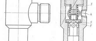
Standard product for installation in circular ducts
This industrial air valve for ventilation functions as follows:
- When air moves in the direction indicated by the arrow, the damper (1) opens slightly.
- It is fixed on a metal axis (3) installed in the holes of the housing (2).
- Under the influence of the force created by the load (5), the disk returns to its original position. Using the screw (6), this part can be positioned in the desired location of the auxiliary rod (7) to change the sensitivity of the device.
- In the lower position, the disc rests on the lock (4).
Using this ventilation check valve as an example, we can point out certain disadvantages in order to more accurately formulate the requirements for the parameters of high-quality equipment:
- There is an adjustment mechanism here. But it is not intended for installation in domestic ventilation ducts hidden inside building structures.
- There are no bearings in the central axle mounting unit. It is possible that during operation of this ventilation check valve, extraneous noise will appear. They will be difficult to eliminate with lubricant, even if the appropriate procedure is performed regularly.
- There are no seals here, so it will not be possible to completely block the air flow in the opposite direction. If you do not leave technological gaps, the risk of the damper jamming will increase.
This product is made of sheet steel, which increases strength (not necessary in this case) and increases weight. Conventional painting does not meet modern requirements for good corrosion protection. The listed facts must be taken into account when creating a design with your own hands, when choosing a suitable model in a retail chain.
The process of creating a check valve with your own hands
| Photo | Step-by-step algorithm of actions with comments |
| The author of the project is going to install a homemade check valve in a 125 mm wide channel under a standard plastic grille. There are no plans to install a forced fan. It was decided to use available materials to save money. The need for modernization arose due to the arrival of unpleasant odors from neighboring premises located on other floors of the house. | |
| This cover can be removed without any difficulty. It is attached to strips of tape (with two adhesive sides). Over time, they have ceased to perform their functions, so more reliable means will be used for new fixation. | |
| After removing the tape and dirt, a good basis was obtained for creating the necessary design. | |
| Cardboard, thin plywood, or a sheet of plastic are suitable for the valve frame. In this case, empty writing paper packaging was used. The corrugated lid has the necessary strength. An additional advantage is that damping sound vibrations is not useful here. But it can be used when creating a structure with a fan. | |
| To avoid damaging the workpiece, use a soft lining. | |
| The outline of the lattice is outlined with a pencil, and a rectangle is cut out from the lid along the marked lines. | |
| Next, measure the width and height of the ventilation hole. It turned out 125 x 170 mm. | |
| Using a ruler and pencil, the detail is drawn in the center of the rectangle. The distances from opposite edges to its perimeter should be the same. | |
| A vertical jumper 10-15 mm wide is placed in the central part. It will be useful for attaching the valve, which can be made from a suitable piece of thick polymer film. The author used the top part of a standard office folder (binder). | |
| First, cut out the central parts. | |
| Next, the valve flaps are created. They should converge in the closed state in the middle of the central bridge. If less rigid plastic is used, install an additional horizontal support bar in each hole. | |
| The valves are attached to the side parts of the frame using tape. Check the strength of the fastenings and the functioning of the mechanism. | |
| The multi-colored surface of the box will be visible through the cracks. | |
| To eliminate this drawback, the workpiece is covered with white paper. | |
| Using a practical experiment, you can test the functionality of the check valve for ventilation with your own hands. It is necessary to make sure that the petals move freely and reliably block the access of air when closed. | |
| To increase the test duration, the valve is mounted on self-tapping screws without tightening them completely. The locations of the holes are marked in accordance with the lattice parameters. If everything is in order, it is installed on top and attached with screws to the wall along with the valve. |
How to install it yourself
In order to correctly install the ventilation air valve with your own hands, you need to perform a number of actions:
- Study the diagram of the ventilation system and choose a place to install the valve.
- Inspect the location of the proposed installation of the ventilation valve.
- Disconnect the hood from the mains and dismantle it if necessary.
- Install the valve into the air duct and mark its attachment points.
- Prepare a place for fastening, insert dowels if necessary.
- Install the device, securing it securely.
- Seal the cracks with silicone. Lack of tightness in the seams will significantly impair air exchange.
- Install all other ventilation elements.
There are models that can be installed in front of the exhaust fan. These are overhead models and are much easier to install.
The grille with the device is installed at the inlet or outlet of the ventilation duct. To attach it, you can use liquid nails or self-tapping screws.
At the outlet of the ventilation duct, a single-leaf gravity valve or a double-leaf spring valve is often installed
It is important that a powerful fan is installed
Options for working connection schemes
Heating systems are very diverse and the presence of a check valve is not necessary in all of them. Let's consider several cases when its installation is necessary. First of all, a check valve must be installed on each of the individual circuits in a closed circuit, provided that they are equipped with circulation pumps.
Some craftsmen strongly recommend installing a spring-type check valve in front of the inlet pipe of the only circulation pump in a single-circuit system. They motivate their advice by the fact that in this way pumping equipment can be protected from water hammer.
This is in no way true. Firstly, installing a check valve in a single-circuit system is hardly justified. Secondly, it is always installed after the circulation pump, otherwise using the device loses all meaning.
If two or more boilers are included in the heating circuit, the occurrence of parasitic flows is inevitable. Therefore, connecting a check valve is mandatory
For multi-circuit systems, the presence of a reverse-acting shut-off device is vital. For example, when two boilers are used for heating, electric and solid fuel, or any others.
When one of the circulation pumps is turned off, the pressure in the pipeline will inevitably change and a so-called parasitic flow will appear, which will move in a small circle, which can lead to trouble. It is impossible to do without shut-off valves here.
A similar situation arises when using an indirect heating boiler. Especially if the equipment has a separate pump, if there is no buffer tank, hydraulic arrow or distribution comb.
Here, too, there is a high probability of a parasitic flow, to cut off which a check valve is needed, which is used specifically for arranging a branch with a boiler.
It is mandatory to use shut-off valves in systems with bypass. Such schemes are usually used when converting a scheme from gravitational fluid circulation to forced circulation.
In this case, the valve is placed on the bypass parallel to the circulation pumping equipment. It is assumed that the main mode of operation will be forced. But if the pump is turned off due to lack of electricity or breakdown, the system will automatically switch to natural circulation.
When installing bypass units for heating circuits, the use of check valves is considered mandatory. The figure shows one of the possible bypass connection options
This will happen as follows: the pump stops supplying coolant, the check valve actuator unit ceases to experience pressure and closes.
Then the convection movement of the liquid along the main line resumes. This process will continue until the pump starts working. In addition, experts suggest installing a check valve on the make-up pipeline. This is not necessary, but highly desirable, since it allows you to avoid emptying the heating system for a variety of reasons.
For example, the owner opened a tap on the make-up pipeline to increase the pressure in the system. If, by an unpleasant coincidence, the water supply is cut off at this moment, the coolant will simply squeeze out the remaining cold water and go into the pipeline. As a result, the heating system will be left without liquid, the pressure in it will drop sharply and the boiler will stop.
In the circuits described above, it is important to use the correct valves. To cut off parasitic flows between adjacent circuits, it is advisable to install disk or petal devices
In this case, the hydraulic resistance will be lower in the latter option, which must be taken into account when choosing.
In heating systems with natural coolant circulation, the use of spring check valves is impractical. Only paddle rotators can be installed here
To install a bypass unit, it is preferable to choose a ball valve. This is due to the fact that it provides almost zero resistance. A disc-type valve can be installed on the make-up pipeline. This should be a model designed for fairly high operating pressure.
Therefore, a check valve may not be installed in all heating systems. It is necessarily used when installing bypasses of all types for boilers and radiators, as well as at pipeline branch points.
Types of air valves for ventilation
Some types of ventilation valves
There are several classifications by which ventilation dampers are divided:
- by appointment;
- according to form;
- by function;
- according to the control method.
When dividing by purpose, it is customary to distinguish the following groups of devices:
Air valves. Their main purpose is to regulate the gas supply. They are used when working with non-flammable gases, fumes and suspensions. The temperature of the transported flow should not exceed 80 °C.
The maximum permissible pressure is 1500 Pa. Scope of application: warehouses, apartments, vegetable stores, etc.
Fire dampers. There are 2 models of valves available: smoke and fire-retardant.
Explosion-proof. A special type of fire damper. The design is made in such a way as to prevent sparks from passing through it.
Unified. The most common type. Used in air conditioning and air heating systems. They have found application both in everyday life and in industry.
Devices can be distinguished by shape:
- round;
- rectangular;
- square.
Based on the installation principle, there are built-in and overhead models.
Devices may differ by drive type:
Equipped with manual drive. They are marked "P". At the extended end of the axis there is either a handle or a special profile tip (in this case, rotation is carried out using a special key).
Equipped with electric drive. In this case, the marking “E” is applied. control is carried out via a servo drive located on the valve body. Most often it is installed in ventilation ducts and shafts of increased diameter.
Equipped with pneumatic drive. The device body is marked “P”. They differ from models equipped with an electric drive only in the drive device itself.
It is important to mention the classification related to the functions performed by the valves:
- check valve;
- emergency device;
- normally open;
- normally closed;
- spring loaded;
- exhaust type;
- other models.
The valve control can be either manual or automatic or using a control panel.
Let's consider the types and principles of operation
In an apartment building, a vertical ventilation shaft box starts in the basement and goes to the roof. In each apartment the branches end with bars.
There are three types of ventilation in buildings:
- Natural outflow of air due to pressure differences in the mines.
- Forced draft on fans for air inlet and outlet. With an autonomous system, the fan operates on the façade of the building. Supply valves are installed. With a centralized network, supply and exhaust units create draft in the house around the clock.
- Combined options. Air is supplied forcibly and naturally leaves through the shaft. In the second option, it comes through the windows and is removed using exhaust fans.
Connecting a hood with your own hands disrupts standard ventilation. During installation, a hole is punched, but the section of the shaft does not change. To improve air exchange, install a flapper valve. It blocks reverse draft when the hood is operating. After it is turned off, the valve opens.
Instructions for self-construction of the valve
As you already understand, to create a ventilation system with backdraft protection, it is not at all necessary to buy a ready-made structure. Of course, you won’t be able to do it completely without cost, since you will have to buy an exhaust fan. This will be the basis for the check valve.
Before starting work, you should prepare all the necessary tools and materials. So, to build a diaphragm valve you will need a piece of plastic and thick plastic film
It is also important to immediately prepare a drill, screws, rubber gaskets and glue
To understand how to properly make a check valve for ventilation with your own hands, it is important to read the following instructions. All exhaust fans are manufactured according to already established standards, corresponding to the ventilation duct openings in private and apartment buildings
All exhaust fans are manufactured according to already established standards, corresponding to the ventilation duct openings in private and apartment buildings
We cut out a plate from thick plastic strictly according to the shape of the hole in the ventilation duct. Actually, this will be the basis of the future valve.
Next, we drill several holes along the edges to attach the panel to the wall and fix the fan. The number of holes can be adjusted independently.
We also drill several holes in the center of the plate through which exhaust air will be discharged. You will also have to determine their number yourself, based on your personal needs. The more holes in the center of the plate, the greater the valve's capacity.
Next, we attach the hood to the finished base. First, you will need to install a rubber gasket at the connection point, and only then can you fix the fan. This will ensure the necessary tightness, and therefore improve the quality of the valve.
To avoid annoying noise coming from the fan during operation, it is recommended to place small pieces of rubber under the fasteners of the device.
The thickness of the plastic for the construction of the membrane valve must be at least 4-5 mm, so that under the pressure of even a small air flow, flexible membranes can easily bend
We make flaps for the valve from thick polyethylene film. First of all, you will need to cut the film to the size of the base, and only then glue it to the base of the valve
Please note that the flaps must completely cover the ventilation openings
The next stage is to cut the sash into two equal parts, and it is important that the cut is as even as possible. In this case, it is recommended to use a stationery knife with a sharp blade.
We install the finished valve in the ventilation duct, securing it to the wall with several self-tapping screws. Since there are gaps between the wall and the valve, it is advisable to immediately get rid of them using sealant.
This completes the process of creating and installing a diaphragm valve. By sequentially performing all of the above steps, you should end up with a reliable device that protects the room from backdraft.
Features of installation and operation
Installing a ventilation grille with a check valve is not difficult, however, before starting the procedure it is worth performing several preparatory measures:
- Check the device for possible jamming.
- Make sure that the dimensions of the device are comparable to the size of the ventilation hole.
- Make sure that the wall surface around the ventilation duct is suitable for installing fasteners.
- Pre-mark the location for fastening.
- Carefully drill the required number of holes and drive in the dowels.
Next, the grille is installed in place and secured with self-tapping screws. Do not over-tighten the bolts, as the lightweight plastic housing may crack. Some models allow fastening from the inside, into the end of the ventilation duct. The fasteners are not noticeable, but the installation procedure itself will be more complicated.
An alternative (albeit less reliable) method of fastening is the use of adhesives. A layer of glue is evenly applied to the wall around the ventilation hole, or to the back of the grille itself. The grille is pressed tightly against the wall and secured with construction tape. After the glue has completely dried, the tape is removed.
Before installing the grille, it is worth checking that the valve is positioned correctly. Deviation from the correct orientation (depending on the device model) is fraught with incorrect operation, when the valve will not be able to completely block the reverse draft and will essentially be useless. Correcting errors after fastening (especially with the use of foam or glue) will be problematic, since it will require complete dismantling of the valve.
https://youtube.com/watch?v=a5pyuvONFhc