Hi all! This topic will be of interest to owners of fairly powerful 220 volt compressors and a crappy network...
The more efficient the compressor, the more difficult it is for it to start when the voltage drops. To facilitate starting, powerful compressors are equipped with unloading valves and starting capacitors. If the compressor stops starting, then first of all you should check the inertia switch of the starting capacitor.
It stands on the shaft of the electric motor.
looks something like this
more detailed photo
when the engine does not rotate it closes the contacts of the starting capacitor
If everything is fine, the engine starts easily and naturally!
when the engine spins up to the design speed, the weights begin to move away from the axis of rotation, the pressure disappears and the circuit opens.
Let me tell you, the design is completely unreliable...
The mechanism itself tends to slide to the side, so you have to check it periodically. otherwise the contacts will not press tightly and will burn like in my photo.
And the knot itself is crooked to the point of disgrace. When replacing this contact group, I spent a long time modifying it with a file...
and at the same time I slightly drilled the mounting hole on the shaft. so I hope it doesn’t crawl away)))
BUT for the future there are plans to replace this gravitsap with a time relay and contactor. This will be much more reliable.
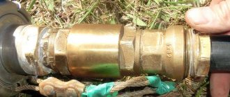
The relief valve is a separate issue. Everyone has a basic one. it is located in the pressure switch
If the valve in the pressure switch is working, then after the compressor pumps up the receiver and turns off, a characteristic sneeze is heard, this is the valve releasing pressure from the line.
It is from the line, the thick tube that goes from the head/heads to the receiver, and not from the receiver. Pressure is not released from the receiver thanks to the check valve
2 thick taps are the input of the main line and the output to the receiver, and the thin one is a tap to the pressure switch.
Some compressors are equipped with an additional pressure-type unloader valve. it lets air into the atmosphere up to a certain pressure and then closes.
Thereby allowing the compressor to spin up and reach operating speed.
It is placed in front of the check valve!
I didn’t have it, so to make life easier for the compressor I added it myself.
I didn’t want to cut the tubes, so I had to resort to using a tee and adapters
But at any moment everything can be returned to its original state.
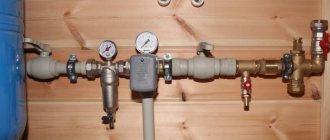
If everything works and the compressor still starts only when the receiver is empty, then you will have to turn on the unloading pre-receiver.
From a 1-2 liter cylinder and insert it into the highway
After the compressor fills the main receiver and the valve in the pressure switch turns off, it releases pressure from the line and from the pre-receiver embedded in it
A small fire extinguisher ala OP-2 is well suited for such purposes.
But there is a better idea!
It’s two in one) At the same time, the air is cooled before entering the receiver)))
To ensure the correct operation of compressor equipment, various technical devices are used, among which is a check valve for the compressor. Without this unit it is almost impossible to imagine the operation of equipment designed for air compression.
Pressure switch for a compressor: independent connection and configuration
In most cases, inexpensive models of air compressors are not equipped with a pressure switch, since such products are mounted on the receiver. Based on this, many manufacturers think that visual monitoring of pressure using a pressure gauge will be more than sufficient. However, during long-term operation of the device, if you do not want to cause the engine to overheat, it makes sense to install a pressure switch for the compressor! With this approach, the drive will be turned off and started automatically.
Circuit and device
The device is divided into the following types:
- Starting the electric motor of the compressor when the pressure drops below the set value (normally closed);
- Switching off the engine when the air pressure rises above the normal level (normally open).
The executive element in the device is springs. Their compression force is measured using a special screw. As a rule, manufacturers adjust the compression force of the springs so that the pressure in the pneumatic network is in the region of 4-6 at. This parameter is always precisely indicated in the instructions.
Since the flexibility and stiffness of springs always largely depends on temperature, all elements of industrial pressure switches are designed and created taking into account subsequent operation at temperatures from minus 5 to plus 80 degrees.
The pressure switch includes 2 mandatory subassemblies in its design - a mechanical switch and a relief valve. A mechanical switch protects against accidental starting of the engine, thus performing the stand by function. After pressing, the device drive starts, after which the compressor begins to operate in automatic mode. Without pressing the button, the electric motor will not work even with reduced pressure in the pneumatic network.
The unloading valve is connected to the air supply line between the compressor and the receiver and is responsible for engine operation. When the compressor drive is turned off, the unloader valve on the receiver gets rid of excess compressed air, thus relieving the moving parts of the extra effort required when restarting the compressor. This eliminates overloading of the engine during torque. When the unloaded engine is turned on, the valve closes, which prevents unnecessary load from being created.
For greater safety, the pressure switches are additionally equipped with safety valves , which turn out to be very useful, for example, in case of piston failure, sudden stop of the electric motor and in any other emergency situation!
A thermal relay can also be installed in the pressure switch housing, allowing you to monitor the current strength in the primary circuit. When this parameter is increased, the thermal relay will automatically turn off the engine, thus protecting the device from overheating and breakdown of the windings.
Check valve
A check valve (return valve) is a device that allows compressed air to flow in only one direction. Structurally, it is assembled (see figure) in a metal case (item 3), inside of which the following are located:
- internal shutter (item 6), blocking the inlet;
- a spring (pos. 4) pressing the rubber ring (pos. 5) to the bolt seat;
- inlet fitting (pos. 7);
- plug (item 1) with a sealing gasket made of cardboard (item 2) (the plug makes it possible to disassemble the return for repair or maintenance).
On a note! The check valve has a branch for connecting it to the receiver and a small branch for connecting a pressure switch.
Operating principle
The reverse action valve works as follows. Passing through the outlet valve of the piston cylinder, the compressed air enters the return pipe through the inlet fitting (pos. 7). Having reached a certain pressure, the air lifts the internal shutter (pos. 6) and passes through the cavity in the housing (pos. 3) into the storage tank of the receiver. When the compressor is turned off, the spring (item 4) returns the internal shutter to its place, blocking the path of air from the receiver back into the piston cylinder.
Varieties
On the domestic market you can find compressors with returns made of three different materials: aluminum, plastic and brass. At the same time, the aluminum part differs from its analogues in its high reliability and durability. It is built inside the air duct that connects the piston cylinder to the receiver, and is capable of operating under high temperature conditions (up to 200°C). Whereas a plastic return line is installed in budget models operating at a low temperature of the working environment. As for valves made of brass, they are widely used. Such return valves are quite reliable and perfectly maintain their performance characteristics in cases where the air temperature during compression does not exceed 140°C.
Recommendations for selection
If the compressor return valve fails, it is not difficult to replace it with a similar one
However, before you buy a new valve, you need to pay special attention to the diameter of the threads cut on the outlets of its body. After all, the connecting dimensions of the return, compressor and receiver may differ from each other
Advice! When going for a new check valve for your compressor, do not forget to take the failed part with you. This will greatly facilitate the selection procedure for a new node.
It is also necessary to take into account the technical characteristics and operating conditions of the compressor. After all, there are valves that are not designed to work with high-pressure compressor equipment. In addition, when the working medium heats up to a high temperature during compression, the use of plastic returns is impractical - it is better to purchase a unit in a metal case, which is mounted inside the air duct connecting the compressor and the receiver. It will not be superfluous to purchase a collapsible design - this will allow you to buy the appropriate repair kit in the future and fix the return fault yourself, replacing the failed parts with purchased spare parts.
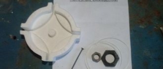
Making a check valve yourself
In cases where it is not possible to purchase a new check valve to replace a faulty one, you can make it yourself from scrap materials. For this you will need:
- female tee;
- spring;
- 2 couplings with external thread, the diameter corresponding to the internal thread of the tee;
- a ball whose diameter is larger than the size of the internal hole in the coupling;
- a metal plug with an external thread that matches the internal thread on the tee.
The valve is assembled in the following sequence: first, the coupling is screwed into one of the branches of the tee, then a ball is inserted into the tee on the other side, and then the plug is screwed in, pressing the ball with a spring.
There are several practical tips for making a return line.
- It is best to take the ball from an old computer mouse - it has a rubberized surface that will fit more tightly to the edges of the hole.
- You can also use a regular piece of pipe of suitable diameter as a body. True, in this case you will have to drill a side hole in it, weld another bend and cut threads at all ends.
- The spring must press the ball with a certain force and in no case should it be weakened.
Connecting and setting up a pressure switch
The pressure switch in the compressor installation circuit is located between the secondary engine control circuit and the unloader valve. As a rule, a pressure switch for a compressor is equipped with 4 threaded heads, one of which is intended for connecting the control pressure gauge, the second for connecting the device to the receiver. A ¼-inch threaded plug is installed on one of the remaining ones, and a safety valve is installed on the last one. The presence of a free connector makes it possible to place the control pressure gauge in the most convenient place.
The pressure switch is connected in the following order:
- A device is connected to the unloading valve of the receiver.
- A control pressure gauge is placed. Otherwise, the threaded entry is plugged.
- The motor control circuits are connected to the terminal contacts. If the network voltage changes, then the connection should be made through a surge protector ! This is also necessary when the contact power exceeds the indicator for which the engine is designed.
- The compressed air pressure readings can be adjusted if necessary using adjusting screws.
Before connecting the pressure switch to the compressor, it is worth checking that the network voltage corresponds to what is specified by the manufacturer! For example, a two-contact group is used for a three-phase network with a voltage of 220V, a three-contact group is used for a voltage of 380V.
The setup is performed with the receiver at least 2/3 full. To do this, the relay is disconnected from the power supply, after which, with the cover removed, the compression of the springs is adjusted. The maximum operating pressure is determined by the adjusting screw with the axis of the larger spring. The second adjusting screw, with a smaller spring, allows you to adjust the pressure difference. In most cases, the manufacturer indicates on the board the direction of rotation for increasing and decreasing pressure. Here you can also see the generally accepted designation for pressure - the Latin letter “P” and “ΔP”.
In some models, to reduce the time required to adjust the pressure, the manufacturer places the adjusting screw outside the pressure switch housing. In this case, the result is controlled based on the pressure gauge readings.
Check valve
A check valve (return valve) is a device that allows compressed air to flow in only one direction. Structurally, it is assembled (see figure) in a metal case (item 3), inside of which the following are located:
- internal shutter (item 6), blocking the inlet;
- a spring (pos. 4) pressing the rubber ring (pos. 5) to the bolt seat;
- inlet fitting (pos. 7);
- plug (item 1) with a sealing gasket made of cardboard (item 2) (the plug makes it possible to disassemble the return for repair or maintenance).
Operating principle
The reverse action valve works as follows. Passing through the outlet valve of the piston cylinder, the compressed air enters the return pipe through the inlet fitting (pos. 7). Having reached a certain pressure, the air lifts the internal shutter (pos. 6) and passes through the cavity in the housing (pos. 3) into the storage tank of the receiver. When the compressor is turned off, the spring (item 4) returns the internal shutter to its place, blocking the path of air from the receiver back into the piston cylinder.
Varieties
On the domestic market you can find compressors with returns made of three different materials: aluminum, plastic and brass. At the same time, the aluminum part differs from its analogues in its high reliability and durability. It is built inside the air duct that connects the piston cylinder to the receiver, and is capable of operating under high temperature conditions (up to 200°C). Whereas a plastic return line is installed in budget models operating at a low temperature of the working environment. As for valves made of brass, they are widely used. Such return valves are quite reliable and perfectly maintain their performance characteristics in cases where the air temperature during compression does not exceed 140°C.
Recommendations for selection
If the compressor return valve fails, it is not difficult to replace it with a similar one
However, before you buy a new valve, you need to pay special attention to the diameter of the threads cut on the outlets of its body. After all, the connecting dimensions of the return, compressor and receiver may differ from each other
It is also necessary to take into account the technical characteristics and operating conditions of the compressor. After all, there are valves that are not designed to work with high-pressure compressor equipment. In addition, when the working medium heats up to a high temperature during compression, the use of plastic returns is impractical - it is better to purchase a unit in a metal case, which is mounted inside the air duct connecting the compressor and the receiver. It will not be superfluous to purchase a collapsible design - this will allow you to buy the appropriate repair kit in the future and fix the return fault yourself, replacing the failed parts with purchased spare parts.
Making a check valve yourself
In cases where it is not possible to purchase a new check valve to replace a faulty one, you can make it yourself from scrap materials. For this you will need:
- female tee;
- spring;
- 2 couplings with external thread, the diameter corresponding to the internal thread of the tee;
- a ball whose diameter is larger than the size of the internal hole in the coupling;
- a metal plug with an external thread that matches the internal thread on the tee.
The valve is assembled in the following sequence: first, the coupling is screwed into one of the branches of the tee, then a ball is inserted into the tee on the other side, and then the plug is screwed in, pressing the ball with a spring.
There are several practical tips for making a return line.
- It is best to take the ball from an old computer mouse - it has a rubberized surface that will fit more tightly to the edges of the hole.
- You can also use a regular piece of pipe of suitable diameter as a body. True, in this case you will have to drill a side hole in it, weld another bend and cut threads at all ends.
- The spring must press the ball with a certain force and in no case should it be weakened.
DIY pressure switch
If you have a working thermostat at home from an old refrigerator, as well as some operating skills, then you can easily make a pressure switch for the compressor with your own hands. However, it is worth warning in advance that such a solution will not have great practical possibilities, since the upper pressure with such an approach will be limited only by the strength of the rubber bellows.
It is most convenient to convert the KTS 011 thermal relay into a pressure switch, because they differ in the reverse operating sequence - when the temperature in the chamber decreases, they turn off, and when the temperature in the chamber increases, they turn on.
Work order
After opening the cover, the location of the required group of contacts is determined, and for this purpose the circuit is ringed. The first step is to modify the connection of the compressor with the thermal relay: the contact groups are connected to the terminals of the electric motor circuit, and the unloading valve is connected to the outlet pipe with a control pressure gauge. The adjusting screw is located under the thermal relay cover.
Pressure switch for compressor: device, marking + connection diagram and adjustment
The use of an air pneumatic relay allows you to automate the filling of the compressor receiver with compressed gas. The operator of equipment with a pressure switch does not need to monitor the process, trying to fix the limit parameters. As a result, engine damage is prevented. Significant results, right?
If you are planning to purchase a pressure switch for your compressor, then you have come to the right place. Here you will find a vast amount of extremely useful information about the principles of operation of the device, its configuration and connection methods.
We have described in detail the existing types of pneumatic relays. They provided options for connecting to a household and industrial network with extremely clear diagrams. We looked at typical breakdowns and ways to prevent them. The information and useful tips we provide are supplemented with graphic, photo and video applications.
Operating principle of a pressure switch
The name of the relay is determined by its purpose - controlling a piston compressor to maintain the required atmospheric pressure in the receiver. It is rarely found on a screw type device responsible for compressing and supplying air.
I take into account the magnitude of the pressing force in pneumatic automation; the device acts on the voltage line, closing or opening it. Thus, insufficient pressure in the compressor starts the motor, and when the required level is reached, it turns it off.
This standard operating principle, based on connecting a normal closed loop to a circuit, is used to control the motor.
Modifications with the opposite operating algorithm are also presented: when reaching minimum values in the compression circuit, the pressure switch turns off the electric motor, and at maximum values it activates. Here the system operates in a normally open loop.
The operating system is made up of spring mechanisms with varying degrees of rigidity, reproducing the response to fluctuations in the air pressure unit.
During operation, the indicators formed as a result of the elastic force of tension or compression of the springs and the pressure of the atmosphere pressed by the device are compared. Any changes automatically activate the action of the spiral and the relay unit connects or disconnects the electricity supply line.
However, it is worth considering that the design of the review model does not provide for regulatory influence. Exceptional impact on the engine. In this case, the user has the opportunity to set a peak value, upon reaching which the spring will fire.
How to make a check valve with your own hands
There are situations when the air compressor return valve has failed, and for some reason it is not possible to buy a new part. In this case, the part can be made by hand.
On the Internet you can find quite complex methods for manufacturing this unit using lathes, milling machines and other equipment. But there is still a way to make a simple homemade valve from improvised materials. A drawing of this unit is shown below.
To make a return you will need a metal pipe or tee, a spring, a coupling, a metal threaded plug and a ball.
The air check valve is manufactured as follows.
- Take a piece of metal tube of the required size and cut internal threads on both sides.
- Drill a hole in the side of the tube and weld a tap (with thread). The receiver will be connected to it. You can also try to find a suitable tee. In this case, there will be no need to weld the outlet.
- Screw the coupling into one part of the tube (tee), as shown in the drawing.
- Place the ball into the body and press it with a spring. The spring should press the ball with sufficient force and not be too loose.
- Pressing the spring, tighten the metal plug. At this stage, the production of the return line is completed.
After this unit is ready, its inlet pipe is connected to the cylinder of the unit, and the second to the receiver.
Hi all! This topic will be of interest to owners of fairly powerful 220 volt compressors and a crappy network...
The more efficient the compressor, the more difficult it is for it to start when the voltage drops. To facilitate starting, powerful compressors are equipped with unloading valves and starting capacitors. If the compressor stops starting, then first of all you should check the inertia switch of the starting capacitor.
It stands on the shaft of the electric motor.
looks something like this
more detailed photo
when the engine does not rotate it closes the contacts of the starting capacitor
If everything is fine, the engine starts easily and naturally!
when the engine spins up to the design speed, the weights begin to move away from the axis of rotation, the pressure disappears and the circuit opens.
Let me tell you, the design is completely unreliable...
The mechanism itself tends to slide to the side, so you have to check it periodically. otherwise the contacts will not press tightly and will burn like in my photo.
And the knot itself is crooked to the point of disgrace. When replacing this contact group, I spent a long time modifying it with a file...
and at the same time I slightly drilled the mounting hole on the shaft. so I hope it doesn’t crawl away)))
BUT for the future there are plans to replace this gravitsap with a time relay and contactor. This will be much more reliable.
The relief valve is a separate issue. Everyone has a basic one. it is located in the pressure switch
If the valve in the pressure switch is working, then after the compressor pumps up the receiver and turns off, a characteristic sneeze is heard, this is the valve releasing pressure from the line.
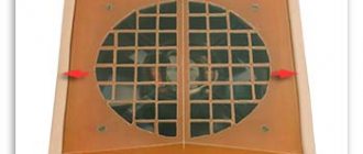
It is from the line, the thick tube that goes from the head/heads to the receiver, and not from the receiver. Pressure is not released from the receiver thanks to the check valve
2 thick taps are the input of the main line and the output to the receiver, and the thin one is a tap to the pressure switch.
Some compressors are equipped with an additional pressure-type unloader valve. it lets air into the atmosphere up to a certain pressure and then closes.
Thereby allowing the compressor to spin up and reach operating speed.
It is placed in front of the check valve!
I didn’t have it, so to make life easier for the compressor I added it myself.
I didn’t want to cut the tubes, so I had to resort to using a tee and adapters
But at any moment everything can be returned to its original state.
If everything works and the compressor still starts only when the receiver is empty, then you will have to turn on the unloading pre-receiver.
From a 1-2 liter cylinder and insert it into the highway
After the compressor fills the main receiver and the valve in the pressure switch turns off, it releases pressure from the line and from the pre-receiver embedded in it
A small fire extinguisher ala OP-2 is well suited for such purposes.
But there is a better idea!
It’s two in one) At the same time, the air is cooled before entering the receiver)))
An air compressor is a unit whose operating principle is based on compressing and supplying air to pneumatic equipment under the required pressure. Such installations are an indispensable element both in everyday life and in industry, being an autonomously functioning technical unit or being included in more complex electrical appliances (for example, climate control or refrigeration equipment). The schematic diagram of any compressor includes a working chamber and a valve system. And since these devices, like any other mechanisms, can break down, you need to know how they are designed, what types of valves there are, how to choose them correctly or make them yourself. More on all this in the material below.
Complete set of compressor automation unit
The relay design is a small-sized block equipped with receiving pipes, a sensing element (spring) and a membrane. Mandatory subassemblies include an unloading valve and a mechanical switch.
The pressure switch sensing unit is made up of a spring mechanism, the compression force of which is changed by a screw. According to the factory standardized settings, the elasticity coefficient is set to a pressure in the pneumatic chain of 4-6 at, as reported in the instructions for the device.
The degree of rigidity and flexibility of the spring elements is subject to the temperature of the environment, therefore absolutely all models of industrial devices are designed for stable operation in an environment from -5 to +80 ºC.
The reservoir membrane is connected to the relay switch. During movement, it turns the pressure switch on and off.
The unloading element is located between the ejector check valve and the compression block. If the motor drive stops working, the unloading section is activated, through which excess pressure (up to 2 atm) is released from the piston compartment.
With further start or acceleration of the electric motor, a pressure is created that closes the valve. This prevents overloading of the drive and simplifies starting the device in switched off mode.
There is an unloading system with a time interval of activation. The mechanism remains in the open position when the engine starts for a specified period. This range is enough for the engine to achieve maximum torque.
Recommendations for selection
When choosing a check valve, you should consider a number of parameters. These include, in particular:
- the intensity of the air flow that will be transported through the system;
- the performance of the air exchange device on which the check valve will be installed;
- the power of the air pumping device, which can be a compressor or fan;
- the degree of contamination of the working environment that will be transported through the elements of the system being created;
- temperature operating conditions.
In addition, it is necessary to take into account the type of medium with which the elements of the valve device will come into contact. This parameter has a direct impact on the choice of valve material, which must have the required durability.
Types of pressure switch devices
There are only two variations in the design of the automatic compressor unit. The determination is made based on their operating principle. In the first version, the mechanism turns off the electric motor when the established limits of the air mass pressure level in the pneumatic network are exceeded. These devices are called normally open.
Another model with the opposite principle - turns on the engine if a drop in pressure is detected below the permissible level. Devices of this type are called normally closed.
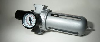
Design and principle of operation of the pressure regulator
A gas pressure regulator or pressure reducing valve is designed to reduce the pressure in the line diverted from the main line and maintain this pressure at a constant level.
Pressure regulators are used to maintain the pressure required for the operation of pneumatic, gas or other equipment.
For example, pressure reducing valves are installed on gas cylinders and allow you to adjust the required pressure in the line discharged to the consumer. Reducing valves installed on cylinders are often called pressure reducers, since they reduce or reduce the pressure in the outlet line (reduction - reduction, reduction, reduction).
Structure of pneumatic relay symbols
The marking of the air pressure switch indicates the entire optional set of the device, design features, including information about the factory settings for the pressure differential.
Let us examine the designations in more detail using the example of devices for air ejectors RDK – (*) (****) – (*)/(*):
- RDK – series of relays for compressors;
- (*) – number of threaded ports: 1 – one port with 1/4”NPT internal thread; 4 – four connectors;
- (****) – type of housing design: T10P – version 10 with a “lever” switch; T10K – “button” switch; T18P – execution 18 with a “switch” switch; T19P – 19 s;
- (*) – factory settings of the threshold response: 1 – 4…6 bar; 2 – 6…8 bar; 3 – 8…10 bar;
- (*) – diameter of the unloading valve: the absence of a symbol means a standardized parameter of 6 mm; 6.5 mm – 6.5 mm.
The difference between the minimum and maximum pressure thresholds is set by the manufacturer and, as a rule, has a value of 2 bar.
However, it is also possible to manually adjust the range of two values – maximum and minimum, but only downward.
The specifics of setting up pressure switches for pumping stations are outlined in the following article, the contents of which we recommend that you familiarize yourself with.
Types and principles of operation of valve mechanisms
Currently, the most common types of compressors are screw and piston units. At the same time, screw compressors, for example, those produced by the Belarusian plant REMEZA, are widely used in various industries, and piston compressors are used in everyday life. The latter can be found both in garages of car enthusiasts (compressors such as SO-7B, Forte VFL-50, etc.) and in life support systems for fish in aquariums (Resun compressors, etc.), as well as in household pneumatic tools.
Piston compressors are characterized by a simple design and a relatively small number of parts and components. There are many different designs of such compressor units, equipped with special plate valves that regulate the process of suction and injection of air during operation . Depending on the purpose of compressor units (their performance, power and operating pressure), three types of valve mechanisms can be found:
Inlet and exhaust valves
Inlet and outlet valve assemblies play such a role in the operation of compressor equipment.
- The movement of the piston to bottom dead center causes air to be drawn in through the open suction valve.
- When the bottom point is reached, the piston begins to move in the opposite direction. At the same time, the suction valve closes, and the air in the sealed chamber begins to decrease in volume under the influence of piston pressure.
- When approaching top dead center, the discharge valve opens and air compressed under high pressure begins to flow into the receiver.
- Having displaced the air from the chamber, the piston again begins to move to the bottom dead center, and the working cycle is repeated.
Unloader and safety valves
Thus, the compressor pumps air into the receiver cycle by cycle until the specified pressure value is reached. This process is monitored by a special pressure switch (pressostat), which controls the operation of the electric motor by turning it on and off depending on the degree of air compression. As a rule, the pressure switch also includes a starting unloading valve. A pressure switch is connected between the output of the compressor head and the check valve (return valve), which is connected to the receiver and holds the compressed air there.
Important! The safety valve is responsible for relieving air pressure. Its functions include: ensuring a smooth start of the compressor and preventing the return of compressed air to the compression chamber after the engine is turned off.
The necessary pneumatic equipment is connected directly to the receiver, which can be additionally equipped with various devices (separators, filters, pressure equalizers, etc.).
Air relay connection diagrams
The compressor pressure switch is manufactured for connection to electrical circuits of different loads. In accordance with the rating of the power supply line, the appropriate model of the relay unit is selected.
Option #1: to a network with a nominal value of 220 V
If the drive motor is a single-phase device, then a 220 V relay with two groups of contacts is installed.
Option #2: to a three-phase network with a voltage of 380 V
For a three-phase load of a 380 V circuit, one of the options can be used: a modification of the relay for 220 V or 380 V, with three contact lines, to simultaneously disconnect all three phases.
Both methods have different schemes. Let's consider the first option:
By choosing the second method, power is supplied from one phase (zero) and in this case the relay rating should be 220 V. For more details, see the following diagram:
After connecting to the power supply, you need to understand the additional capabilities provided in the air blocks for ejectors.
Installation of relays and auxiliary elements
In some modifications of pressure switches, you can find additional equipment in the form of flange connections, through which additional equipment is connected. These are basically three-way parts, with a ¼-inch diameter.
To put the device into operation, it must be connected to the receiver. Installation consists of the following steps:
- The device is connected to the compressor through the main outlet.
- A pressure gauge is connected to the device with flanges. There may also be other auxiliary mechanisms that require activation: a safety or unloading valve.
- Channels that are not used for connection must be closed with plugs.
- Next, according to the electrical diagram, the relay is connected to the contacts of the motor control circuit.
Motors with low power can be connected directly; in other cases, additional installation of an electromagnetic starter of appropriate power is required.
Before moving on to setting the threshold response parameters, it is worth paying attention to the operating conditions. First, adjustments are made under pressure. Secondly, the electrical supply to the engine must be cut off.
What does the device consist of and how does it work?
The design consists of the following main parts:
At normal or reduced air pressure, the compression force of the spring tightly presses the locking element to the seat. The air passage is closed.
As soon as the pressure begins to exceed the actuation value, it overcomes the force of the spring and begins to push the locking element away from the seat. A gap opens for air to pass through. Air is released into the atmosphere, and its pressure inside the system decreases. The spring force again overcomes the pressure force and pushes the locking element back to the seat. The shutter closes and is ready for the next air release cycle.
Possible malfunctions of the device
Several malfunctions characteristic of pressure switches are noted. In most cases, they are simply replaced with new devices. However, there are minor problems that you can fix yourself without the help of a repairman.
The most common malfunction is characterized by air leakage from the relay when the receiver is turned on. In this case, the culprit may be the start valve. It is enough to replace the gasket and the problem will be eliminated.
Frequent starting of the compressor indicates loosening and displacement of the adjusting bolts. Here you will need to double-check the threshold for turning on and off the relay and adjust them according to the instructions in the previous section.
Troubleshooting methods
A more difficult problem lies ahead if the compressor does not work. There may be several sources. Let's consider one of them - melting of the pressure switch contacts due to erosion arising from electrical sparks.
To eliminate this type of malfunction, you can use one of the following methods: clean the surface, which extends the service life by at least 3 months, or repair it by replacing the contacts in the terminal clamps.
Step-by-step instructions for the second option:
- Bleed all air from the receiver and turn off the power to the ejector. Remove the pressure switch.
- Having removed the protective housing, disconnect the wiring connected to the group of contacts.
- Using a screwdriver, you need to remove the terminal with contacts and drill out the burnt lines from it.
- You can replace the wire with copper wire. It is necessary to select it taking into account the diameter of the hole, since it must fit tightly into the seat. It is inserted into the hole and pressed on both sides.
- Similar actions are performed with the remaining burnt lines.
- After the contact group is assembled, it is mounted in its original place and the pressure switch cover is screwed on.
The compressor relay operates in difficult conditions, subject to wear and failure.
Although the repair is not cost-effective, those familiar with the device can perform the repair themselves. However, the option of replacing it with a new device still remains profitable.
Why do you need an overpressure relief valve?
The device is designed to protect the system from exceeding operating pressure. The emergency valve is activated when the threshold pressure value is exceeded, opens and releases part of the air into the atmosphere. At the same time, the pressure drops to normal, and the air pressure relief valve closes.
When the compressor stops, compressed air remains in its cylinders. The unloading valve is activated when the engine is turned off, releasing air into the atmosphere.
If this is not done, subsequent startup of the unit will be difficult or even impossible.
In addition, storing the compressor without increased pressure in the cylinders increases its service life.
Emergency air release valves must be installed on the compressor in case of failure of the pressure switch relay.