Types of deformation
Deformation is a change in the shape or size of the body.
There are several types of deformation:
- shift;
- torsion;
- bend;
- compression/extension;
Shear deformation occurs when some parts of the body move relative to other parts of the body. If we apply a horizontal force to the top of a cardboard box filled with various objects, we will cause the top of the box to shift relative to its bottom.
Compression or stretching is easy to imagine using the example of a rectangular piece of thin rubber. This deformation is used, for example, in elastic bands for clothing.
Examples of bending and torsion are shown in Figure 1. A plastic ruler deformed by bending is shown in Figure 1. 1a, and in Figure 1b - the same ruler deformed by torsion.
Rice. 1. plastic ruler, deformed by bending – a) and torsion – b)
In a deformable body, forces arise that are of an electromagnetic nature and prevent deformation.
Determination of tensile stiffness coefficient
To determine the tensile stiffness coefficient, the following calculations are performed.
- The length of the spring in a vertical suspension with one free side of the product is measured - L1;
- The length of the spring with a suspended load is measured - L2. If you take a load weighing 100g, then it will act with a force of 1N (Newton) - value F;
- The difference between the last and first length indicators is calculated - L;
- The elasticity coefficient is calculated using the formula: k = F/L.
The compression stiffness coefficient is determined using the same formula. Only instead of hanging, the load is installed on the top of a vertically mounted spring.
To summarize, we conclude that the spring stiffness indicator is one of the essential characteristics of the product, which indicates the quality of the source material and determines the durability of the final product.
Calculation of elastic force
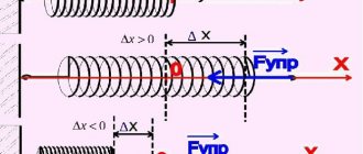
If we stretch a spring by hand, we can notice that the more we stretch the spring, the more it resists.
This means that the elongation of the spring is associated with a force that resists this elongation.
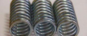
Of course, if the spring is elastic enough to resist. For example, a multi-colored toy spring (Fig. 3), made of plastic, will practically not resist stretching, which doubles its length.
A multi-colored plastic toy spring has little resistance to stretching.
Hooke's law
The English physicist Robert Hooke, who lived in the second half of the 17th century, established that the resistance force of a spring and its elongation are directly proportional. He called the force with which a spring resists deformation (F_{text{upr}}) the force of elasticity.
[ large boxed{ F_{text{control}} = k cdot Delta L }]
This formula was called Hooke's law of elasticity.
( F_{text{control}} left( H right) ) – elastic force;
( Delta L left(text{м} right) ) – spring extension;
( displaystyle k left(frac{H}{text{m}} right) ) – stiffness (elasticity) coefficient.
What deformations are called small
Hooke's law is used for small elongations (strains).
If the deforming force is removed and the body returns to its original shape (size), then the deformations are called small.
If the body does not return to its original shape, the deformation cannot be called small.
How to calculate the stiffness coefficient
A weight attached to the end of the spring stretches it (Fig. 4). Let's measure the elongation of the spring and create a force equation for the projection of forces on the vertical axis. The weight of the load is directed against the axis, and the elastic force opposing it is directed along the axis.
Rice. 4. The weight of a load suspended on a spring is balanced by the elastic force
Since the forces cancel each other, there is a zero on the right side of the equation.
[ large F_{text{control}} — m cdot g = 0 ]
Let us substitute the expression for the elastic force into this equation
[ large k cdot Delta L — m cdot g = 0 ]
We add the weight of the load to both parts and divide by the measured change in length (Delta L) of the spring. We obtain an expression for the stiffness coefficient:
[large boxed{ k = frac{ m cdot g }{Delta L} }]
(g) is the acceleration of gravity, it is related to the force of gravity.
We connect two identical springs
In physics problem books and textbooks for preparing for the Unified State Exam, there are problems in which identical springs are connected in series or in parallel.
Parallel connection of springs
Figure 5a shows a freely hanging spring. Let's load it (Fig. 5b), it will stretch by an amount (Delta L). Let's connect two such springs in parallel and hang a load in the middle of the crossbar (Fig. 5c). The figure shows that a structure of two parallel springs under the action of a load will stretch less than a single such spring.
Rice. 5. Two springs connected in parallel are deformed less than one such spring
Let us compare the stretch of two identical springs connected in parallel with the stretch of one spring. We hang one weight (mg) from the springs.
One spring:
[ large k_{1} cdot Delta L = m cdot g ]
Two parallel springs:
[ large k_{text{parallel}} cdot Delta L cdot frac{1}{2}= m cdot g ]
Since the right sides of the equations are the same, the left sides will also be equal:
[ large k_{text{parallel}} cdot Delta L cdot frac{1}{2}= k_{1} cdot Delta L ]
Both sides of the equation contain the value (Delta L). Let's divide both sides of the equation by it:
[ large k_{text{parallel}} cdot frac{1}{2}= k_{1} ]
Let's multiply both sides of the resulting equation by the number 2:
[ large boxed{ k_{text{parallel}} = 2k_{1} } ]
The stiffness coefficient (k_{text{parallel}}) of two springs connected in parallel has doubled compared to one such spring
Series connection of springs
Figure 6a illustrates a free-hanging spring. Loaded spring (Fig. 6b), stretched to length (Delta L). Now let's take two such springs and connect them in series. Let's hang a load on these (Fig. 6c) springs.
Practice shows that a structure of two springs connected in series under the action of a load will stretch more than a single spring.
Each spring in the chain is subject to the weight of the load. Under the influence of weight, the spring stretches and transmits this weight further along the chain without changes. He stretches the next spring. And that, in turn, stretches by the same amount (Delta L).
Note: Under the influence of force, the spring stretches and transmits this tensile force further along the chain without changes
Rice. 6. A system consisting of two identical springs connected in series, more than one spring is deformed
Let's compare the stretch of two identical springs connected in series and the stretch of a single spring. In both cases, we suspend the same weight (mg) from the springs.
One spring:
[ large k_{1} cdot Delta L = m cdot g ]
Two springs in series:
[ large k_{text{last}} cdot Delta L cdot 2 = m cdot g ]
Since the right sides of the equations are the same, the left sides will also be equal:
[ large k_{text{last}} cdot Delta L cdot 2 = k_{1} cdot Delta L ]
Both sides of the equation contain the value (Delta L). Let's divide both sides of the equation by it:
How to calculate spring stiffness
To calculate the stiffness coefficient, the formula is used:
k = G * (Dw)^4 / 8 * Na * (Dm)^3,
where G is the shear modulus. This value can not be calculated, since it is given in tables for various materials. For example, for ordinary steel it is 80 GPa, for spring steel it is 78.5 GPa. From the formula it is clear that the remaining three quantities have the greatest influence on the spring stiffness coefficient: the diameter and number of turns, as well as the diameter of the spring itself. To achieve the required rigidity indicators, it is these characteristics that must be changed.
Read also: Copper-phosphorus solder for copper soldering
You can calculate the stiffness coefficient experimentally using the simplest tools: the spring itself, a ruler and a load that will act on the prototype.
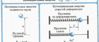
Potential energy of a compressed or stretched spring
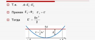
A spring compressed (left part of Fig. 7) or stretched (right part of Fig. 7) by a length (Delta L) has the potential to return to its original state and at the same time do work, for example, to move a load. In such cases, physicists say that the spring has potential energy.
Rice. 7. A deformed - compressed or stretched spring has potential energy
This energy depends on the spring constant and on its elongation (or shortening during compression).
The greater the stiffness (elasticity) of the spring, the greater its potential energy. By increasing the elongation of the spring, we obtain an increase in its potential energy according to the quadratic law:
[ large boxed{ E_{p} = frac{k}{2} cdot left( Delta L right)^{2} }]
( E_{p} left( text{J} right)) – potential energy of a compressed or stretched spring;
( Delta L left(text{м} right) ) – spring extension;
( displaystyle k left(frac{H}{text{m}} right) ) – spring stiffness (elasticity) coefficient.
Conical coil compression springs
In cases where it is necessary to significantly reduce the overall dimensions of the spring in a compressed state, this type of spring is used.
The height of these springs in a compressed state is equal to the thickness of one turn. The conical spring is wound in such a way that when compressed it resembles an Archimedes spiral with a pitch “a” slightly exceeding the thickness of the wire
Maximum stresses occur in the coil with the largest radius.
The spring displacement is found using the formula:
When calculating the moving units of a mechanism that move due to the accumulated energy of springs, it becomes necessary to determine the parameters of this spring that provide the specified response time or the required speed of the unit.
Maximum stresses occur in the coil with the largest radius.
The spring displacement λ is found by the formula:
When calculating the moving units of a mechanism that move due to the accumulated energy of springs, it becomes necessary to determine the parameters of this spring that provide the specified response time or the required speed of the unit.
Response time:
where: - reduced mass and all forces acting on this node (to the end of the spring
in a compressed state).
If the force P is displaced relative to the axis, this leads to undesirable operating conditions. Compression springs lose stability, and extension springs bend under the influence of additional torque. The coaxiality of the acting force P and the spring is achieved by using various methods of securing the ends of the spring.
Helical torsion springs
They are used for elastic connection in couplings, closing kinematic chains of various mechanisms, as position clamps and energy accumulators. To ensure longitudinal stability of the springs during operation, they are mounted on a guide stand. In this case, one end of the spring is fixed to a stationary stand, and the other is loaded with force P.
Under the influence of the moment PI = M, the spring is twisted. In this case, in the sections of the turns, normal stresses arise from the bending moment Mi - M cosa and tangent stresses from the torsional moment Mi = M sina, where a is the angle of elevation of the helix of the spring. The effect of tangential stresses on the spring strength can be taken into account by introducing a correction factor K, which, depending on the spring index (C = 4 - 5) is usually equal to 1.2 - 1.1. In this case, the calculation of the spring is carried out only for bending.
The diameter of the wire:
Average spring diameter in free state: Do - cd;
Spring twist angle:
where L is the length of the wire for the operating state of the spring. L= Пcdn0 (n0 is the number of turns in the free state).
And correspondingly:
When choosing a guide rod Dct, it is necessary to take into account the change in the average diameter of the spring and the number of working turns during its deformation. Assuming the length of the wire remains constant
Coil springs
These springs are used both in recorders and in watches and other mechanisms. A spiral spring creates a moment acting in a plane perpendicular to its axis.
Depending on their purpose, coil springs are called torque or winding springs.
Torque is used in devices to create a counteracting moment of a moving system, in lever, gear and other measuring systems - for the force closure of kinematic chains. These springs are often called hairs. They have a small cross-sectional area and develop a small moment. Torque springs are parts of devices on which the accuracy of measuring systems depends. Since they often work in specific conditions, they are subject to the following requirements:
· The dependence of the moment on the angle of twist must be linear.
Line OA is the dependence of M on n without taking into account hysteresis (internal friction). Its loop is shown with dashed lines.
· Imperfections in the properties of elasticity (hysteresis and elastic response) must be less than the error, the value of which is determined by the accuracy class of the device.
· The temperature coefficient of the elastic modulus must be small.
· The spring material must have high corrosion resistance.
· In electrical measuring instruments, the material of torque springs must be antimagnetic and have low resistivity.
The counteracting moment of the spiral spring is determined by the value of the effective torque in the electrical measuring system.
When using it for force closure of the kinematic chain of the device under small inertial loads, its minimum moment at a preliminary angle of twist is found depending on the friction moment reduced to its axis.
where K is the safety factor K = 2 ÷ 3.
Reduced friction moment, equal to the sum of the friction moments in certain components of the mechanism, reduced to the axis of the spring.
The theoretical values of the largest and smallest moments are determined by the formulas:
1 - length of the elastic part of the hair.
Having determined the value of the required torque of the spiral spring using the formula
you can find its geometric parameters from the strength and stiffness equations: where:
L is the length of the hair.
The length of a moment helical spring can be approximately found from the equality of areas equation:
Thus, the condition for normal operation of the hair will be:
To take into account the various loads that arise during the operation of the device (vibrations, temperature...), a hair safety factor nв= 2÷3 is introduced, then:
Reduced friction moment in general form: (equation *).
Where:
- the sum of the friction moments reduced to the axis of the hair, equivalent to the friction moments acting on each of the n axes of the mechanism. MTpj is the moment on one of the n axes, ddi is the rotation angle of the nth axis, corresponding to the rotation of the hair axis by the angle dω.
— the sum of the friction moments reduced to the axis of the hair, equivalent to the friction moments caused by the friction forces Fipj on linear movements dsj in each of the m translational pairs of the mechanism.
The number of turns and the pitch of the spiral are determined by the formulas:
To ensure a linear characteristic, it is necessary to fasten the outer and inner ends of the helical spring so that during deformation its turns remain concentric. The figure shows methods for attaching mainsprings, which serve to accumulate mechanical energy in spring motors.
Spring motors come in two types: with a movable finishing drum and with a fixed one. Motors with a moving drum are more often used.
As we have already discussed, torque springs are often used in transmission mechanisms to eliminate gaps and the like. During operation of the measuring device, due to deflection of the pointer when hitting the stop and residual deformation of the spring, the arrow may not return to its original position. To set the arrow to its original position (zero mark), install a corrector.
In some cases, the initial part of the scale of the measuring device should correspond to high sensitivity, and the final part to lower sensitivity. For this purpose, a spring with variable stiffness is used.
A limiter (1) is placed in the middle part of the spring, and a stop (2) is placed in the stationary part of the device. When the roller is rotated at a certain angle corresponding to the contact stop with the stop, the entire spring works. The sensitivity is high. In this case, the characteristic will be depicted as a flat straight line AC. When turning further
roller to a larger angle, not the entire spring will work, but only part of it from the roller to the stop. The spring stiffness increases, the sensitivity decreases, and the characteristic becomes steeper - the CD segment.
Steel strips and bronze are used as materials for the manufacture of torque springs.
When calculating hairs, the safety factor is . Great importance
The coefficient is taken to obtain small residual deformations and ensure the constancy of the elastic properties of the hair.
The minimum hair moment, which is created by twisting the hair when installed in the device, must be greater than all the friction moments arising in the moving joints of the transmission mechanism in order to bring all moving parts of the reading device to their original position.
The total effect of the friction moments arising in the movable joints of the transmission mechanism is characterized by the friction moment reduced to the axis of the hair
The reduced moment of friction to any axis of the mechanism is the moment applied to this axis that is equivalent to the total action of all forces and moments of friction in the transmission mechanism.
conclusions
- Elastic bodies are those that resist deformation;
- During deformation, a force arises in elastic bodies, it prevents deformation, it is called the elastic force;
- Deformation is a change in the shape or size of the body;
- There are several types of deformation: bending, torsion, shear, tension/compression;
- The elongation of a spring is the difference between its final and initial lengths;
- A compressed or stretched spring has potential energy (in general, any elastically deformed body has potential energy);
- A system consisting of several identical springs will have a stiffness coefficient different from that of a single spring;
- If the springs are connected in parallel, the stiffness coefficient of the system increases;
- And if you connect the springs in series, the stiffness coefficient of the system will decrease.