When are calculations needed?
Parameters are calculated using a calculator or using online programs
It is important to know what area the pipeline surface should have in the following cases.
- When calculating the heat transfer of a “warm” floor or register. Here the total area is calculated, which transfers heat emanating from the coolant to the room.
- When heat losses are determined along the way from a source of thermal energy to heating elements - radiators, convectors, etc. To determine the number and size of such devices, we need to know the amount of calories that we must have, and it is derived taking into account the development of the pipe.
- To determine the required amount of thermal insulation material, anti-corrosion coating and paint. When constructing highways that are kilometers long, accurate calculations save the enterprise considerable money.
- When determining a rationally justified profile section that could ensure maximum conductivity of the water supply or heating network.
Determination of pipe parameters
Cross-sectional area
The pipe is a cylinder, so calculations are not difficult
The cross-section of a round profile is a circle, the diameter of which is determined as the difference in the outer diameter of the product minus the wall thickness.
In geometry, the area of a circle is calculated as follows:
S = π R^2 or S= π (D/2-N)^2, where S is the internal cross-sectional area; π – number “pi”; R – section radius; D—outer diameter; N is the thickness of the pipe walls.
Note! If in pressure systems the liquid fills the entire volume of the pipeline, then in a gravity sewer only part of the walls is constantly wetted. In such collectors, the concept of open cross-sectional area of the pipe is used.
External surface
The surface of the cylinder, which is the round profile, is a rectangle. One side of the figure is the length of the pipeline section, and the second is the circumference of the cylinder.
Pipe development is calculated using the formula:
S = π DL, where S is the pipe area, L is the length of the product.
Inner surface
This indicator is used in the process of hydrodynamic calculations, when the surface area of the pipe that is constantly in contact with water is determined.
When determining this parameter, you should consider:
- The larger the diameter of the water pipes, the less the flow rate depends on the roughness of the walls of the structure.
On a note! If pipelines with a large diameter are characterized by a short length, then the value of the wall resistance can be neglected.
- In hydrodynamic calculations, the roughness of the wall surface is given no less importance than its area. If water flows through a water pipe that is rusty inside, then its speed is less than the speed of the liquid that flows through a relatively smooth polypropylene structure.
- Networks that are mounted from non-galvanized steel are characterized by a variable internal surface area. During operation, they become covered with rust and overgrown with mineral deposits, which narrows the lumen of the pipeline.
Important! Pay attention to this fact if you want to make cold water supply from steel material. The throughput of such a water supply system will be halved after ten years of operation.
The calculation of the pipe development in this case is made taking into account the fact that the internal diameter of the cylinder is determined as the difference between the external diameter of the profile and the double thickness of its walls.
As a result, the surface area of the cylinder is determined by the formula:
S= π (D-2N)L, where the indicator N is added to the already known parameters, which determines the wall thickness.
The workpiece development formula helps to calculate the amount of thermal insulation required
To know how to calculate the development of a pipe, it is enough to remember the geometry course that is taught in middle school. It’s nice that the school curriculum is used in adult life and helps solve serious problems related to construction. Let them be useful for you too!
Determination of the dimensions of the workpiece during bending is carried out as a development of the part, with the lengths of straight sections and the lengths of curves calculated from the neutral layer being summed up. Such calculations do not present significant difficulties. In practice, when bending particularly complex parts, it is recommended to obtain their development experimentally, since it is not always possible to accurately calculate it theoretically.
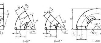
There are two main cases of bending: 1) along a curve of a certain radius; 2) at a rounding angle at r
Bending along a curve of a certain radius.
To determine the length of the workpiece, you can use the method of unwrapping a part, based on the fact that the neutral line retains its original dimensions during bending and is located in places of curves at a distance x
0 s
from the inside of the product
(Fig. 2.4).
Therefore, to determine the length of the blank of a complex part, one should sum the length of the straight sections of the bent product with the length of the rounded sections, calculated from the neutral layer.
For a part with one bend at an angle, the length of the workpiece is determined by the formula
, (2.13)
where l 1, l 2 – length of straight sections of the bent product, mm;
l
0
- length of the neutral layer of the rounded section,
mm
;
r
— radius of curvature,
mm
;
Bending angle, degrees;
x
0
is a coefficient that determines the position of the neutral layer.
For a part with several angles, the length of the workpiece is determined by the formula
Rice. 2.4 Calculation of workpiece length
For small elastoplastic deformations (when bending workpieces with a relative radius of curvature r
/ s >5
), it is assumed that the neutral layer passes through the middle of the thickness of the strip
p(p 0 ) = p cf
, that is, its position is determined by the radius of curvature
p = r + s / 2
.
A x 0
is found by the formula:
For significant plastic deformations, which occurs when bending workpieces with a relative radius of curvature, bending is accompanied by a decrease in the thickness of the material and a displacement of the neutral layer towards the compressed fibers. In these cases, the radius of curvature of the neutral deformation layer should be determined by the formula:
where is the thinning coefficient of the material (the thickness of the material after bending, mm).
The thinning coefficient during bending depends on the type of material, the relative radius of the bend and the bending angle. The distance of the neutral layer from the inner surface of the bent workpiece when bending wide strips is determined by the formula
The values of the coefficients and x
about
for bending are given in reference books.
Bending at an angle without rounding.
When bending at an angle without roundings or with roundings of very small radius ()
, which is accompanied by a significant thinning of the metal at the bend points, to determine the size of the workpiece (Fig. 2.5) before bending AB and after bending AVG, they use the mass equality method.
Fig.2.5 Calculation of workpiece length
In practice, the following formula is used:
, (2.20)
where L is the length of the workpiece;
The amount of increase (allowance) of material to form an angle.
Typically, this value, depending on the hardness and thickness of the material, is taken equal to each angle. Moreover, the softer the material, the smaller the increase, and vice versa.
The length of the workpiece for n right angles can be determined by the formula:
During sequential bending. When bending corners at the same time, bending is accompanied by stretching of the material in the middle and at the ends of the sections. In this case, the stretching of the material occurs over most of the bent workpiece, so that here the formation of corners occurs partially due to the stretching of the material of the straight sections. Therefore, for these cases, it is recommended to take half the increase in the length of the workpiece than with sequential bending, that is, accept.
Elements of the workpiece located in the deformable zone and adjacent to the inner surface of the bent part (from the punch side) are subject to compression, and those adjacent to the outer surface (from the matrix side) are subject to tension. Between the stretched and compressed fibers there is a neutral line whose length does not change (Drawing 106).
Crap. 106
Neutral line radius
R in mm (drawing 106) is determined by the formula
where r is the bending radius, mm;
s - material thickness mm;
x is a coefficient, the value of which depends on the ratio r/s (Table 48).
Table 48
| r/s ratio | ||||||||||
| Coefficient x | 0,323 | 0,340 | 0,356 | 0,367 | 0,379 | 0,389 | 0,400 | 0,413 | 0,421 | 0,426 |
| r/s ratio | 10 or more | |||||||||
| Coefficient x | 0,441 | 0,445 | 0,463 | 0,469 | 0,477 | 0,780 | 0,485 | 0,490 | 0,495 | 0,500 |
When curling hinges (loops), due to the presence of external friction forces that prevent deformation, the coefficient x is determined from the table. 48a.
Table 48a
| r/s ratio | ||||
| Coefficient x | 0,56 | 0,54 | 0,52 | 0,51 |
Development length
bending part L p in mm (Fig. 107) is determined by the formula
L р =(l 1 +l 2 +l 3 +. . .)+ π / 180 (φ 1 R 1 +φ 2 R 2 +φ 3 R 3 +. . .) (47)
where l 1; l 2 ; l 3 - straight sections, mm;
φ 1; φ 2; φ 3 — bending angles, degrees;
R1; R2; R 3 - radii of the neutral line, determined by formula (46).
Crap. 107
When bending materials with a thickness of more than 3 mm at an angle of 90° with a bending radius r≤s, the radius of the neutral line R, calculated according to formula (46), must be adjusted to the value R 1 (Fig. 108), based on the condition of material integrity and mating in points a and a 1 of a curved section of radius R 1 with straight lines a-a and a 1 -a 1 passing through the middle of the thickness s. In section C-C 1, the dotted line shows the outer contour in the calculation without taking into account the thinning of the material. Due to thinning during bending, the thickness s 1 in this area is less than the original s.
Crap. 108
The values of R 1 for the radius of the adjusted neutral line and the length of the arc aba 1 should be calculated using the formulas
R is determined by formula (46); r—bending radius, mm; other designations are shown in Fig. 108.
Elements for determining the dimensions of the reamers of commonly used bent parts are given in Table. 49.
Table 49
Note
:
- y, y 1, y 2 - values that take into account the change in the development length when bending at an angle of 90°. For material thickness up to 2.5 mm, they are taken according to the table. 50, and with a thickness of 3 mm or more at r
- x - coefficient, taken according to the table. 48a.
Table 50
Table 50a
Example
. Determine the length of the development for the part shown in Fig. 109.
Crap. 109
According to table.
49 L р =l+l 1 + y, where l and l 1 are the lengths of the straight sections of the bent part;
y - find from the table. 50a
At s=4 mm and r= 3.5 mm
L p =50+40+ 1.22=91.22 mm.
If one-sided tolerances are specified in the working drawing of a part, then to calculate the length of the development, these tolerances must be recalculated to two-sided ones, while maintaining the specified tolerance field. In this case, the nominal dimensions of the part must also be recalculated (Fig. 110).
Crap. 110
In table 51 and 52 provide formulas for calculating the sweep length
bent parts with different initial data on the working drawing and different forms of mating.
Table 51
Note
: x - coefficient, determined from table. 48.
Table 52
Let's consider a situation that often arises in bending production. This is especially true for small workshops that make do with small and medium-sized mechanization. By small and medium mechanization I mean the use of manual or semi-automatic sheet benders. The operator sums up the length of the shelves, obtains the total length of the workpiece for the required product, measures the required length, cuts and... after bending, receives an inaccurate product. Errors in the dimensions of the final product can be quite significant (depending on the complexity of the product, the number of bends, etc.). This is because when calculating the length of the workpiece, it is necessary to take into account the thickness of the metal, the bending radius, and the coefficient of the position of the neutral line (K-factor). This is exactly what this article will focus on.
So let's get started.
To be honest, calculating the dimensions of the workpiece is not difficult. You just need to understand that you need to take into account not only the lengths of the shelves (straight sections), but also the lengths of the curved sections resulting from plastic deformations of the material during bending.
Moreover, all the formulas have long been derived by “smart people”, whose books and resources I constantly indicate at the end of the articles (from there, if you wish, you can get additional information).
Thus, in order to calculate the correct length of the workpiece (part development), which ensures the required dimensions after bending, it is necessary, first of all, to understand which option we will use to make the calculation.
I remind you:
So if you want shelf surface A
without deformations (for example, for the location of holes), then you calculate according to
option 1
.
If the overall height of shelf A
, then, without a doubt,
option 2
is more suitable.
Option 1 (with allowance)
We will need:
c) Sum up the lengths of these segments. In this case, the lengths of straight sections are summed up without change, and the lengths of curved sections are summed up taking into account the deformation of the material and the corresponding displacement of the neutral layer.
So, for example, for a workpiece with one bend, the formula will look like this:
Where X
1
is the length of the first straight section,
Y 1
is the length of the second straight section,
φ
is the external angle,
r
is the internal bending radius,
k S
is the thickness of the metal.
Thus, the calculation progress will be as follows..
Y1 + BA1 + X1 + BA2 +
..etc
The length of the formula depends on the number of variables.
Option 2 (with deduction)
In my experience, this is the most common calculation option for rotary beam bending machines. Therefore, let's look at this option.
We also need:
a) Determine the K-factor (see table).
b) Divide the contour of the bending part into elements, which are straight segments and parts of circles;
Here it is necessary to consider a new concept - the outer boundary of bending.
To make it easier to imagine, see the picture:
The outer boundary of the bend is this imaginary dotted line.
So, to find the length of the deduction, you need to subtract the length of the curved section from the length of the outer boundary.
Thus, the formula for the length of the workpiece according to option 2:
Where Y
2
,
X 2
– flanges,
φ
– external angle,
r
– internal bending radius,
k
– neutral line position coefficient (K-factor),
S
– metal thickness.
Deduction from us ( BD
), as you understand:
Outer bending boundary ( OS
):
And in this case, it is also necessary to calculate each operation sequentially. After all, the exact length of each shelf is important to us.
The calculation scheme is as follows:
(Y2 – BD1 / 2) + (X2 – (BD1 / 2 + BD2 / 2)) + (M2 – (BD2 / 2 + BD3 /2)) +
.. etc.
Graphically it will look like this:
And also, the amount of deduction ( BD
) during sequential calculations, it is necessary to calculate correctly.
That is, we are not just cutting two. First we count the entire BD
, and only after that we divide the resulting result in half.
I hope that I did not offend anyone with this remark. I just know that mathematics is forgotten and even basic calculations can be fraught with surprises that no one needs.
That's all. Thank you all for your attention.
When preparing the information, I used: 1. Article “BendWorks. The fine-art of Sheet Metal Bending” Olaf Diegel, Complete Design Services, July 2002; 2. Romanovsky V.P. “Handbook of Cold Forging” 1979; materials from the English-language resource SheetMetal.Me (section “Fabrication formulas”, link:
TECHNOCOM | Online bending force calculator
The calculator for calculating the required force of a press brake allows you to calculate the required tonnage. Useful for technologists and engineers for a general study of the capabilities of their equipment or for selecting a press brake to perform certain bending parameters. Allows you to obtain general reference values in a matter of seconds without complex calculations, including for further selection of bending tools or placing bending orders.
Legend
F (force, tonnage), tons - the total required force for bending S (thickness), mm - thickness of the material (sheet) for bending V (opening), mm - opening of the matrix h (flange length), mm - minimum required length for a straight residual flange parts after bendingL (bending length), mm - main bending length of the part (parallel to the width of the press brake)R (radius), mm - internal bending radius TS (tensile strength) - tensile strength of the part material for bending
The main formula used for calculation is:
Bending force F = (1.42 x TS x S2 x L)/1000 x V Inner radius R = (5 x V) / 32
Attention!
This calculator is intended solely for obtaining indicative reference information and cannot be an effective tool for accurate calculations and preparation of technical specifications. To obtain accurate and reliable values, you must consult with specialists.
Bending force table for press brake
The table below displays the approximate reference force according to die opening, minimum flange, metal thickness and radius. This table is valid for 1 meter of structural steel
| V | H min | R | 0,5 | 0,8 | 1 | 1,2 | 1,5 | 1,8 | 2 | 2,5 | 3 | 3,5 | 4 | 4,5 | 5 | 6 | 7 | 8 | 9 | 10 | 12 | 15 | 18 | 20 |
| 6 | 5 | 1 | 2,5 | 6,5 | 10 | |||||||||||||||||||
| 8 | 6 | 1,3 | 2 | 5 | 8 | 11 | ||||||||||||||||||
| 10 | 7 | 1,7 | 1,5 | 4 | 6 | 9 | 13 | |||||||||||||||||
| 12 | 9 | 2 | 3 | 5 | 7 | 11 | 16 | |||||||||||||||||
| 15 | 12 | 2,7 | 4 | 6 | 9 | 13 | 16 | |||||||||||||||||
| 20 | 15 | 3,3 | 4 | 7 | 10 | 13 | 19 | |||||||||||||||||
| 26 | 18 | 4,2 | 5 | 7,5 | 10 | 14 | 21 | |||||||||||||||||
| 30 | 22 | 5 | 6,5 | 8 | 12 | 19 | 24 | |||||||||||||||||
| 32 | 23 | 5,4 | 7,5 | 11,6 | 17 | 23 | 30 | |||||||||||||||||
| 37 | 25 | 5,8 | 10 | 14,5 | 20 | 26 | 33 | |||||||||||||||||
| 42 | 29 | 6,7 | 13 | 17 | 23 | 29 | 35,5 | |||||||||||||||||
| 45 | 32 | 7,5 | 16 | 21 | 27 | 33 | 48 | |||||||||||||||||
| 50 | 36 | 8,3 | 19 | 24 | 30 | 43 | 58 | |||||||||||||||||
| 60 | 43 | 10 | 20 | 25 | 36 | 49 | 64 | |||||||||||||||||
| 70 | 50 | 11,5 | 21 | 31 | 42 | 55 | 69 | |||||||||||||||||
| 80 | 57 | 13,5 | 27 | 37 | 48 | 60 | 75 | |||||||||||||||||
| 90 | 64 | 15 | 32 | 42 | 54 | 66 | 95 | |||||||||||||||||
| 100 | 71 | 17 | 38 | 48 | 60 | 86 | 134 | |||||||||||||||||
| 130 | 93 | 22 | 37 | 46 | 66 | 103 | 149 | |||||||||||||||||
| 180 | 130 | 30 | 33 | 48 | 75 | 107 | 133 | |||||||||||||||||
| 200 | 145 | 33 | 43 | 67 | 97 | 119 | ||||||||||||||||||
| 250 | 180 | 42 | 54 | 77 | 95 |
www.technocom-rus.ru
Sheet metal unfolding program
The material is bent by hand or on a bending machine, or with stamps under presses. Mostly small-sized parts are bent by hand.
On a bending machine, sheet blanks and parts are bent in a straight line from various materials and at various angles, both to obtain various profiles of box-shaped shapes and for flanging small widths (5-30 mm).
When bending the material, in order to avoid cracks, you need to monitor the bend radius, guided by the data in table. 4.
Table 4 - Bend radii in mm
| Material thickness | Electron | Duralumin | Aluminum, copper, brass | Steel |
| 0,3 | 1.5 | 1.5 | 0,6 | O.6 |
| 0,4 | 1,5 | 1,5 | 0.6 | 0,6 |
| 0,5 | 2.5 | 1.5 | 0,6 | 0.6 |
| 0,6 | 2,5 | 2.5 | 1.0 | 1,0 |
| 0,75 | — | — | 1,0 | |
| 0,8 | 4,0 | 2.5 | 1,0 | — |
| 1,0 | 4.0 | 2.5 | 1,5 | 1,5 |
| 1,2 | 4,0 | 4,0 | 1.5 | — |
| 1,25 | — | — | — | 2.5 |
| 1,5 | 6,0 | 4,0 | 2,5 | 2.5 |
| 1,75 | — | — | 2,5 | |
| 2,0 | 10,0 | 6,0 | 2,5 | 2,5 |
Before bending to a small radius, all parts are annealed. When bending, the material compresses and stretches (Fig. 194).
rice. 194.
Before the bend, the length of the line ab at the upper edge of the sheet blank at the bend is equal to the length of the line сd, located in the middle of the sheet blank, and the line mi at the bottom edge of the sheet blank.
After bending, the length of the arc ab is less than the length of the arcs c and pl.
This inequality shows that when bending, the material on the outside is stretched, and inside the curve it is compressed, and only the middle line CD does not change its length.
When bending sheet blanks from various materials to obtain a part of the required dimensions, the choice of permissible radii and determination of the lengths of the reamers (blanks) are of great importance.
Bending with rounding (Fig. 195) requires a shorter workpiece than bending without rounding (Fig. 196).
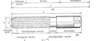
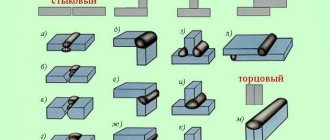
Device for marking pipes. Calculation and production of a template - Equipment
In large procurement workshops, marking and cutting of pipes is carried out on a marking and cutting unit, which makes it possible to obtain pipeline parts with a tolerance of ± 1 mm.
In small procurement workshops and at the installation site, pipe marking is carried out on marking racks using conventional marking and measuring tools: rulers, tape measures, scribers, templates, etc.
Marking the pipe consists of determining its blank length and drawing the necessary axes. Having marked the pipe for cutting, the beginnings of all bends, holes for inserting taps and tees are marked on it.
To manufacture a bent bend and determine the length of the workpiece, the radius (R) and angle (a) of the bend of the pipe, the length of the free ends or the length of the straight section between the bends must be known. The length of the workpiece (Fig. 1) is determined by the formula
Where LTotal is the length of the workpiece, m;
L= π/180*αR – length of the curved part, m;
L1 = L – S – length of the straight section, m;
L2 = L1-S-length of the second straight section, m; .
Figure 1. Marking the pipe for bending
- a – marking of the outlet;
- b – pipeline section.
When two pipes intersect, the cutting tee is marked using a device that is made on a sheet of thick paper. First, the intersection of two pipes is drawn in two projections and in full size, as shown in Fig. 2. A semicircle is built on the embedded part of the pipe, which is usually divided into six parts (points 1, 2, 3, 4, 5, 6). Straight lines parallel to the axis of the pipe are drawn through these points. On the second projection, similar constructions are made, straight lines are drawn until they intersect with the contour of the pipe into which the insertion needs to be made (points 0, 1, 2, 3). Drawing parallel lines from these points, as shown in the figure, we obtain points 0l, 1l, 2l, 3l, 4l, 5l, 6l.
Rice. 5. Marking the intersection of two pipes
Program for calculating the length of development in Excel when bending pipes.
To perform calculations we use MS Excel.
You can use the Calc spreadsheet processor from the free Apache OpenOffice or LibreOffice .
Initial data:
Let's assume that in the example under consideration, the part consists of three straight and two curved sections (as in the diagram above).
1.
We write down the outer diameter of the pipe
D
in millimeters
to cell D4: 57,0
2.
the value of the internal diameter of the pipe
d
in millimeters
to cell D5: 50,0
Attention!!!
If the development length of a solid round bar is calculated, then d =0!
3.
the length of the first straight section
L 1
in millimeters
to cell D6: 200,0
4.
the axial bend radius of the first curved section
R 1
in millimeters
to cell D7: 300,0
5.
the bending angle of the first curved section
α 1
in degrees
to cell D8: 90,0
6.
the length of the second straight section of the part
L 2
in millimeters
to cell D9: 100,0
7.
the axial bend radius of the second curved section
R 2
in millimeters
to cell D10: 200,0
8.
the bending angle of the second curved section
α 2
in degrees
to cell D11: 135,0
9.
the length of the third straight section of the part
L 3
in millimeters
to cell D12: 300,0
10-15.
Entering the initial data into Excel for our example is complete. We leave cells D13…D18 empty.
The program allows you to calculate the development of parts containing up to five straight sections and up to four curved ones. Bending a pipe with a large number of sections requires a slight modernization of the program to calculate the development.
Calculation results:
16.
the length of the first curved section
L 1
in millimeters
in cell D20: =IF(D7=0;0;PI()*D8/180*((4*D7^2-$D$4^2)^0.5+(4*D7^2-$D$5 ^2)^0.5)/4) =469,4
17.
the length of the second curved section
L 2
in millimeters
in cell D21: =IF(D10=0;0;PI()*D11/180*((4*D10^2-$D$4^2)^0.5+(4*D10^2-$D$5 ^2)^0.5)/4) =467,0
18-19.
Since in the example under consideration there are no third and fourth curved sections, then
in cell D22: =IF(D13=0;0;PI()*D14/180*((4*D13^2-$D$4^2)^0.5+(4*D13^2-$D$5 ^2)^0.5)/4) =0,0
in cell D23: =IF(D16=0;0;PI()*D17/180*((4*D16^2-$D$4^2)^0.5+(4*D16^2-$D$5 ^2)^0.5)/4) =0,0
20.
The total length of the part development
L
in millimeters is summed up
in cell D24: =D6+D9+D12+D15+D18+D20+D21+D22+D23 =1536,3
The development length of the curved pipe was calculated using MS Excel.