The invention of Joseph Guillotine (1791, France), named after the inventor of guillotine, worked until 1981 for its intended purpose. The guillotine for cutting metal was developed somewhat later. For an industrial machine to be in demand, it is necessary to create a certain technical base.
The principle of the movement of a knife from top to bottom under the influence of gravity has found application not only in the field of execution of punishments. In 1817, the “death machine” was tested to perform other functions. They began to use it for chopping meat and bones. In the same year, the device was used in the tanning industry, they began to cut leather for boots, hats and outerwear using falling oblique cutters.
Later (in the twenties and thirties of the nineteenth century) the need arose to make metal products. The consumers were steam locomotives. It was for them that it was necessary to cut metal plates into identical sizes. There was no rolled metal yet; in the forge shops, strips and small sheets of metal came out from under the hammer. They were turned into lining parts for steam boilers, driver's cabins, and trailer cars. Conventional cutting with a hammer and chisel could not satisfy the developing railway transport. Rail transport appeared all over the world.
H3121 Guillotine shears for sheet metal processing. Purpose and scope
Guillotine crank shears N3121 were produced in accordance with GOST 6282-64 from 1968 to 1983 and were replaced by a more advanced model NA3121
.
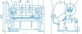
Mechanical guillotine shears N3121 with an inclined knife are designed for cutting sheet metal with a tensile strength (tensile strength) σ BP = 500 MPa (50 kg/mm2). Transverse cutting of sheets up to 12.5 mm thick and up to 2000 mm wide is carried out in one knife stroke. Longitudinal cutting - with a sheet length of more than 2000 mm - is carried out by a series of repeated cuts while moving the sheet along the cutting line.
Design features of guillotine shears N 3121
The guillotine frame is welded, made of sheet steel. Two side posts are connected by a table and three ties. The table to which the lower knife is attached has an adjustment to set the required gap.
The N3121 shears are driven by an electric motor through a V-belt drive and a two-stage helical gearbox; the design of the closed helical gearbox ensures a significant reduction in the noise characteristics of the shears. The guillotine knife beam receives reciprocating motion from the crankshaft through the connecting rods. The knife beam is balanced by a spring balancer.
The force on the knife beam from the crankshaft is transmitted by two connecting rods. Scissor clutch with two rotary keys, band brake, intermittent action. The frequency of braking is achieved due to the eccentric location of the pulley relative to the axis of the crankshaft. This braking occurs when the knife beam is in the upper position, which prevents it from running under the influence of inertial forces.
The engagement clutch is rigid with two rotary keys and an electromagnet. The design of the main drive clutch ensures reliable operation of the sheet shears without air, which significantly reduces operating costs.
The material being cut is pressed against the scissors table by a pressure beam, the movement of which is coordinated with the movement of the knife beam.
Mechanical scissors H3121 are equipped with a back stop . For safe work on the scissors, a protective grid is provided.
H3121 guillotine shears can operate on single and automatic strokes. Push-button control from the control panel and from the foot pedal.
The design of the connection of the knife beam with the connecting rods provides for the possibility of increasing the open height of the knives by 20 mm, which is necessary for longitudinal cutting of the sheet.
pressed to the table by individual spring-loaded rods.
Cutting can be done either according to the markings or using a back stop.
Scissors can be used in warehouses and workshops of various enterprises where cutting sheet steel is required.
When cutting steel with a tensile strength greater or less than 50 kg/mm 2, to calculate the maximum cutting thickness, use the formula specified in the section “Adjusting the scissors.” In this case, the hardness of the sheet being cut should not exceed 35 Rockwell units on the “C” scale.
N3121 scissors are manufactured with basic parameters in accordance with GOST 6282-64
Main parameters of the N3121 machine:
- The largest dimensions of the metal to be cut are 12.5 x 2000 mm
- Ultimate strength (temporary resistance) of metal σ BP, no more than - 500 MPa (50 kg/mm2)
- Maximum cutting force - 500 kN (50 tf)
- Maximum clamping force - 29 kN (2.9 tf)
- Knife stroke frequency, no less than 40 min-1
- Knife stroke - mm
- The tilt angle of the moving knife is 2°10′
- Drive power - 18.5 kW
- Total vehicle weight - 7 tons
Principles of classification
Guillotine shears are distinguished by the following characteristics:
- By type of drive. In industrial production, as well as when cutting thick sheets, driven metal guillotines are more common. In this case, the control can be mechanical or hydraulic. In individual business practice, as well as in private workshops, manually driven machines are found.
- According to the execution of the main actuator. An electromechanical guillotine is most often equipped with a crank mechanism, while manual machines often have a lever mechanism.
- According to the method of pressing the workpiece to the supporting surface of the table. Guillotine shears can have mechanical (spring) or hydraulic clamping.
- According to the control method, cutting shears with non-automated feeding and removal of cut strips are distinguished, and automated complexes based on sheet shears, where all technological operations are carried out without human intervention.
Despite all the design and technological differences, these machines have one thing in common: the angle of inclination of the knives at which they cut. The fact is that at a zero inclination angle, penetration is carried out simultaneously across the entire width of the sheet, which causes increased energy costs and becomes the main reason for the increased drive power. Since the schedule of the technological operation of separating sheet metal has a peak of effort only at the beginning of the introduction of knives, and then rapidly decreases, it is much more profitable to ensure the gradual introduction of the tool into the workpiece. The force is significantly reduced, and the working displacement, although increased, is not much (due to the small thickness of the processed rolled profiles). Therefore, the knives of equipment for cutting sheet profiles are always inclined. The tilt angle ranges from 1.5...3.5°; it is larger for more powerful equipment. When cutting a harder product, for example, stainless steel, the gaps, on the contrary, are reduced. Increasing the gaps for ductile mild steel or copper degrades the quality and accuracy of the cut because the material being cut is pulled into the gap between the blades and forms burrs. Burrs are also a sign of a dull tool.
According to the classification accepted in our country, mechanically driven guillotine shears have the symbol H31__, H32__, H34__ or H33__ (the last two digits of the designation indicate the maximum thickness of the sheet metal being cut). Hydraulic shears are designated H37__. In practice, there is also marking of drive units for cutting sheet material according to its thickness and width. A typical example would be German-made machines, designated, for example, as follows: ScTR16×3150 (the first number is the maximum thickness, the second is the greatest width).
Design of guillotine shears H3121
The shears consist of a frame, knife and pressure beams, drive, drive shafts, engagement clutch, back stop, balancer, brakes, guards, electrical and lubrication systems, and protective grille.
H3121 guillotine shear bed
The bed is the base unit on which all other scissor units are attached. The frame is a welded structure consisting of two racks connected to each other by channels.
The table rests on the racks, to which the lower knives are attached with screws.
To adjust the gap between the table knives and the knife beam, the table is moved with bolts screwed into the ends of the frame with the table fastening bolts relaxed. When regrinding, adjusting the knife height is done by grinding the spacers located under the knives.
The table has extensions with T-slots.
On the right edge of the table there is an extension fixed with pins, in the T-shaped groove of which the cross-cut stop is attached. To perform longitudinal cutting, this stop is removed.
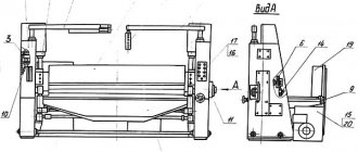
Drive drive shafts of guillotine shears H3121
The shears are driven from an electric motor through a V-belt transmission to the flywheel, through gears and a clutch to the crankshaft (see Fig. 3).
The electric motor is attached to a sub-motor plate, hinged on the frame. Belt tension is adjusted using the eye bolt nuts.
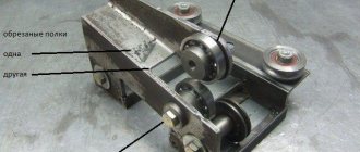
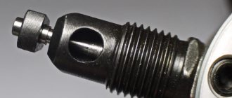
Clutch for turning on guillotine shears H3121
Clutch for turning on guillotine shears N3121
At the left end of the crankshaft, a keyed engagement clutch is installed in the gear hub.
Bushings 1, 2, 3 are stationary in the gear hub. The remaining parts are connected to the crankshaft. The rotating (working and locking) keys of the engagement clutch are activated by springs 6 and, turning, are captured by the semicircular grooves of the sleeve 2.
Bushings 8 and 9, having semicircular grooves, complement the sockets for the round ends of the key. The right end of the working key is equipped with an easily detachable shank 4, which, when the scissors are in operation, disables the keys connected to each other by levers 5. When the keys are turned on, their angle of rotation is limited by the groove of the drive sleeve 8.
Knife beam of guillotine shears H3121
The knife beam is an L-shaped welded structure reinforced with ribs. The back stop is attached to the knife beam.
The force from the crankshaft is transmitted to the knife by two connecting rods; in the upper position, the beam is held by balancing springs, pivotally connected to the beam, and during repairs, it is fixed in the upper position by two Ø25 pins inserted into the hole. knife beam guides.
Clamp and protective grid of guillotine shears H3121
While the scissors are working, the sheet being cut is pressed against the table by a pressure beam. When the knife beam moves downwards, the clamping beam, under the action of springs, lowers and presses the sheet, and first the sheet is pressed, and then the cutting begins. This is achieved by installing the beam at a height of 24 mm, and the knife - 26 mm from the table surface.
The lifting of the clamp is carried out by the stops of the knife beam, resting against the clamping plates.
The clamping force is adjusted using nuts that compress the spring of the clamping beam.
A protective grille is attached to the guides of the pressure beam, protecting the worker’s hands from falling under the pressure. When the scissors are working, the grille is lowered: the M8X40 screw on the left presses the microswitch rod, and the screw on the right limits the rotation of the grille to the clamp.
If necessary, the grille can be raised up, but turning on the scissors is impossible - the switching contacts are open. The grille is held in the lowered and raised position by a 2X16 spring.
Rear scissor stop N3121
The back stop is installed on the back side of the knife beam and serves as a stop for the sheet during cross cutting. The back stop consists of two cylindrical cuts, moved manually by handwheels sitting on gear shafts meshed with racks. By moving the slats, the stop line is set at the required distance from the edge of the knife, which achieves measured cutting of the sheet using the back stop.
Scissor balancer H3121
The balancer is used to hold the knife beam in the upper position after each single stroke - when repairing scissors or changing knives. It consists of two sets of springs installed in cups welded to the upper channel of the frame. The rods are hingedly connected by axes to the knife beam. When the beam is lowered during cutting, the rods compress the springs. During the reverse stroke, the springs, unclamping, help lift the knife beam. Both sets of springs are rated at 1.0 ton with the beam in the top position.
Scissor brake H3121
An intermittent brake is mounted on the right end of the crankshaft. The frequency of braking is achieved due to the eccentric location of the pulley relative to the crankshaft axis.
Braking occurs when the knife beam is in the upper position, which prevents it from running under the influence of inertial forces.
Electromagnetic control of scissors N3121
When you press a button or pedal, an electromagnet is turned on, the armature of which turns the fork with a pin, releasing the shank that engages with it and is connected to the working key. After that, under the action of the key springs, the crankshaft turns and turns on. There is a cut. If the operator does not release the button or pedal in the “Single stroke” mode, an electrical lock is activated (see the electrical equipment section).
To repeat the working stroke, the button or pedal must be released, then pressed again. During automatic operation, the electromagnet armature is set to a stroke of 40 mm, and when operating on single strokes - to 20 mm.
Scissor guard H3121
The shear guard is made of 1.6 mm thick sheet steel and serves to protect the rotating parts of the shears. The guard consists of four casings that cover the motor pulley and the V-belt flywheel, six drive shafts and the scissor brake.
All casings are attached to the frame with M10 bolts.
Lubrication diagram for scissors H3121
Lubrication diagram for scissors N3121
- 1-2 Crankshaft supports - Central lubrication from pump
- 3-4 Crankpins - Centralized lubrication from the pump
- 5-6 Connecting rod pins - Central lubrication from the pump
- 7-8 Knife beam guides - Central lubrication from pump
- 9-10 Pressure guides - Manual lubrication with a syringe
- 11 Clutch - Manual lubrication with a syringe
- 12 Axle of the activation mechanism - Manual lubrication with a syringe
- 13-14 Drive and intermediate shafts - Centralized lubrication from the pump
The main rubbing surfaces are lubricated from a manual pumping station through feeders. Lubrication is carried out through all individual grease nipples installed on the scissors using a manual syringe. The drive gears are lubricated by applying grease to the gear teeth respectively.
During operation, the scissors must be lubricated so that the lubricant comes from the side bearing locations. Any grease that comes out of the gaps must be wiped off. It is necessary to periodically check the condition of the oil nipples and oil passage holes in the parts and be sure to clean them. At least once every three months, the lubrication holes should be flushed with clean kerosene.
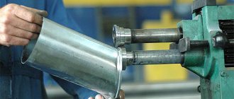
Guillotine for cutting metal
The first installations were manually driven. In order to perform cutting, it was necessary to install not only the knife itself, you also need to have a counter plate (fixed knife).
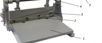
General view of a modern manual guillotine for cutting metal: 1 – table; shear plate; 3 – knife; 4 – crank; 5 – knife feed lever
A manual metal guillotine allows you to cut relatively small workpieces; the cutting width rarely exceeds 1200...1500 mm. In this case, the thickness of the cut parts depends on the material used for manufacturing.
Typically, small industries use similar machines for steel with a thickness of up to 0.5...0.7 mm. You can cut off plastic or different types of films. Flooring factories cut vinyl tiles.
In printing houses, before binding books, brochures and other publications, blocks are formed using manually driven guillotines. Subsequently, they are sent to the press, where printed products are created.
The cutting process on a guillotine machine: 1 – table for feeding material; 2 – metal sheet; 3 – anti-cutting blade; 4 – knife
Gap adjustment
When working, try to reduce the distance between the edges of the blades. The smaller it is, the cleaner the cut. However, when working with metal, operators are forced to move the fixed blade to increase clearance. As the thickness of the metal being cut increases, the distance becomes necessary to increase.
If you do not do this, the edges of the blade will crumble. The metal undergoes deformation changes. It behaves like a plastic substance and is squeezed out between the edges.
Gap δ between cutting edges
The thinner the workpieces, the closer the blades should be placed relative to each other. Table 1 presents recommendations for clearances depending on the thickness of 08 sp steel.
Table 1: Gaps between cutting edges for a manual guillotine when cutting 08 sp steel
| Sheet thickness, mm | Gap between knife and shear plate, mm |
| 0,08…0,095 | 0,02 |
| 0,100…0,195 | 0,03 |
| 0,200…0,295 | 0,04 |
| 0,300…0,395 | 0,05 |
| 0,400…0,495 | 0,06 |
| 0,500…0,595 | 0,07 |
| 0,600…0,695 | 0,08 |
| 0,700…0,800 | 0,09 |
When working on installations with a hydraulic or crank drive, the speed of movement of the knife is higher. Therefore, it is necessary to slightly increase the gap (Table 2).
Table 2: Clearances between cutting edges for mechanical guillotines
| Sheet thickness, mm | Gap between knife and shear plate, mm |
| 0,080…0,095 | 0,04 |
| 0,100…0,195 | 0,06 |
| 0,200…0,295 | 0,08 |
| 0,300…0,395 | 0,10 |
| 0,400…0,495 | 0,12 |
| 0,500…0,595 | 0,14 |
| 0,600…0,695 | 0,16 |
| 0,700…0,800 | 0,18 |
At a high speed of metal displacement (mechanical knives), heating occurs. If you do not increase the gap, then after several consecutive cuts the edges can heat up to such an extent that the metal can weld to the knives.
Oblique cut
When creating the first machines for mass executions, poor-quality cutting sometimes occurred. The straight blade did not cut skin and bone tissue from the first blow. Louis XVI, who was present during the testing of the installation, suggested that the inventor improve the device by making a falling blade with an angle. Sliding entry allows you to optimize the cutting angle and redistribute the load in the device.
When cutting occurs, the meeting of the edge with the material being cut does not occur simultaneously along the entire length of the knife. It gradually penetrates into the metal. Therefore, even a slight tilt, just a few degrees, can significantly reduce the amount of cutting resistance.
Installing the active blade at an angle of inclination β: 1 – active knife; 2 – passive knife; 3 – material to be cut
Modern small guillotine shears work with significant β angles. This is how the designers achieved a noticeable reduction in the forces on the knife. In some enterprises, even women work on such small-sized machines. They cope with the task of cutting metal.
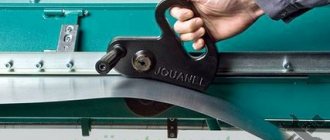
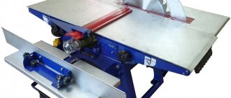
Guillotine shears for cutting metal with manual drive
Adjustment of guillotine shears H3121
During operation of the scissors, the brake, engagement clutch, knife beam, clamp and gap between the knives may be subject to adjustment and adjustment. The operation of the brake must be periodically monitored by adjusting the tension of the springs and preventing contamination of the brake pulley.
The clearances of the knife beam guides and the clamp must be checked regularly in accordance with the feed accuracy.
Adjusting the pressure means that by pressing the spring, the sheet being cut is securely pressed against the table during cutting.
Design and principle of operation
The electromechanical guillotine, a more common design, consists of the following components:
- electric motor;
- V-belt transmission;
- flywheel;
- receiving shaft;
- electro-pneumatic activation system: clutches and brakes;
- main shaft of two-crank type;
- two connecting rods of a pulling or pushing type;
- knife beam. back stop;
- front stop (for units working with thin sheet metal, this unit may be absent);
- desktop;
- clamp;
- welded type beds (in older models of machines there are cast beds);
- working rail cart for collecting cut strips;
- lubrication and control systems.
Industrial versions of mechanically driven sheet metal cutting machines operate in the following sequence. The sheet metal to be cut is set along the back stop to a certain cutting width. In this case, the knife beam is in its uppermost position, the electric motor and flywheel with the receiving shaft rotate, but the beam is motionless, since the brake is on. After positioning the workpiece along the back fence, the operator turns on the front fence, which sets the required cutting accuracy. Next, the clamp is turned on. It is a set of pneumatic or hydraulic cylinders of small working diameters, which with their rods press the sheet metal to be cut to the supporting surface of the table. When the scissors are turned on, the brake is unlocked and the clutch is simultaneously engaged, which connects the main shaft to the receiving shaft. The main actuator performs a forward stroke, at the end of which a complete separation is performed. When the beam returns to its original position, the back stop rotates and releases the cut strip. As a result, it falls along the slide into the cart behind the machine, which is then manually or automatically removed from under the equipment. From the cart, a stack of cut strips is moved by a crane or conveyor to a warehouse or to a place of further processing. The last non-multiple strip is removed manually, while the cylinders of the clamping unit are equipped with protective covers that prevent the operator’s fingers from entering the working area (all scissors are controlled by pedals).
A mechanical guillotine for metal sometimes has a different design. The difference is that the connecting rods of such machines are not of the pulling type, but of the pushing type. They are located in the lower part of the knife beam, and during the working stroke they push it upward. It is believed that such a machine design is characterized by lower working loads on the connecting rods, and guillotine shears with pushing connecting rods have a lower height. This scheme, however, is more complex in routine maintenance and adjustment, and therefore is more typical for machines working with workpieces of small thickness - up to 1.5...2 mm.
Setting up and operating modes of scissors H3121
The scissors are adjusted to cut strips of a given length by moving the back stop. The distance of the back stop from the cutting edge of the lower knife is determined by the scale of rulers mounted on the back stop slats.
The electrical circuit provides for the possibility of operating the machine in the “Single stroke” and “Automatic stroke” modes. Cutting sheets of the maximum thickness and width specified in the technical characteristics of the scissors is not allowed on automatic strokes, since the power of the installed electric motor is designed to use 30% of the number of strokes of the knife beam.
Adjusting the gap between the knives of scissors H3121
When cutting sheets, the gaps between the knives should be set within 1/20 - 1/30 of the thickness of the sheet being cut.
The straightness of the cutting line depends on the correct adjustment of the gap.
The gap between the knives is adjusted by moving the table. It is not allowed to cut sheets of maximum thickness and width from a material with a tensile strength of more than 50 kg/mm2.
In the case of cutting a sheet whose tensile strength (tensile strength) σ is more than 50 kg/mm2, its maximum permissible thickness is determined by the formula:
δ Х = δ√ 50/σВР mm
where δ X is the maximum permissible thickness of a sheet made of a material whose tensile strength is more than 50 kg/mm 2.
δ - maximum permissible sheet thickness for cutting, indicated in the characteristics of the scissors
σВР is the tensile strength of the sheet material that needs to be cut
It must be remembered that the accurate and reliable operation of scissors depends on the quality of sharpening of the knives. Do not cut with dull knives .
When adjusting, it is necessary to maintain the following gaps: Thickness of the sheet being cut, mm - 1; 5÷3; 3÷6.3: 6.3÷12.5. Gap between knives, mm. - 0.15; 0.35; 0.5.
After setting the gap between the blades, tighten the bolts securing the table to the bed.
The knives are made with four cutting edges; if one edge becomes dull, the knives must be periodically turned over.
Main types of guillotine shears
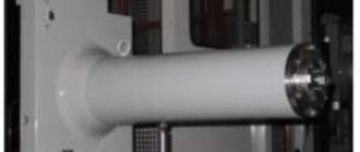
Sample of a German hydraulic guillotine
Industrial workshops, private and home workshops specializing in metalworking are equipped with various types of guillotine shears, which differ in:
- type of drive;
- power;
- type of knives;
- productivity;
- maximum thickness of the metal being cut;
- the range of rental products they can work with;
- size of the processed sheet;
- the number of operations performed.
According to the type of drive, scissors are divided into:
- manual;
- hydraulic;
- pneumatic;
- electromechanical.
Guillotine shears for metal work on the principle of influencing metal simultaneously with a large pressure force and a sharp edge of a knife, operating on the principle of ordinary scissors. The two parts of the knife device are displaced relative to each other. They clamp the sheet or rolled product together and move its adjacent layers, cutting it with a sharp blade.
The guillotine cutting process combines two operations - cutting and breaking.
A good guillotine for cutting industrial metal provides up to 90% of the cut and about 10% of scrap.
Cutting edge with small gap
Cutting edge at optimal clearance
Influence of the gap size on the edge
In this case, the cut is smooth and requires virtually no processing. If the knives are dull or the gap is incorrectly set, then the cut/scrap ratio changes and a sharp protrusion appears on the lower edge - a burr, which indicates poor cutting quality.
The burr can easily cut your hands, especially when working with stainless steel. One of the main safety rules when working with guillotine-type scissors is the use of gloves made of thick fabric or with leather stripes. The appearance of burrs indicates the need to change the settings or sharpen the knives.
Electrical circuit diagram of guillotine shears H3121
Electrical diagram of guillotine shears N3121
The circuit is designed to control a machine with a rigid coupling to clearly engage and disengage the moving slide with the tool. The clutch is activated by an electromagnet, which is activated by an intermediate relay.
Complete shutdown of the circuit is carried out by the input circuit breaker.
Electrical equipment of scissors N3121
The machine is controlled from the control panel. on which control buttons and mode switches are located
The alarm system is electric and light; the designation of modes and controls is symbolic.
Allowed operating mode:
- automatic (continuous running);
- single move.
The machine can be controlled:
- buttons;
- pedal only on single strokes.
The electrical circuit includes the following circuits:
- A. AC power circuit, voltage 380 V.
- b. AC control circuit, voltage 36 V.
- V. AC lighting circuit, voltage 5.5 V.
The following receive power from the power circuit:
- A. Main drive electric motor.
- b. Pulling electromagnet.
- V. The control, lighting and alarm circuits receive power from the secondary windings of the 2T transformer.
Control and protection equipment (transformer, magnetic starters, circuit breaker) are located in the electrical cabinet.
The operation of the scissors is controlled from the control panel.
Description of the operation of the electrical circuit
The electrical circuit provides the ability to operate the scissors in the following modes: “Single stroke”; "Automatic moves."
The selection of the operating mode is carried out by readjusting the scissors (by adjusting the electromagnet thrust) and setting the operating mode switches PR and PU to the desired position, located in the lockable control panel. When resetting the PR and PU switches, the electric motor must be turned off with the 2KU button.
Single move mode
In this mode, operation with a button and a pedal is possible. The PR switch is set to the “Single stroke” position. The thrust of the electromagnet is mechanically adjusted.
a) Button Control
The PU switch is set to the “Button” position. When you press the “Drive Start” button (2KU) along the circuit 1-9-7-15-19-23-3-2, the magnetic starter 1K is turned on, which turns on the main drive electric motor (1D).
Through the normally closed contacts of the 4KU button and the 2K magnetic starter, the 1RP relay receives power via circuit 19-17-115-21-2, becomes self-powered, and with its normally open contacts (circuit 25-31) prepares the 2K magnetic starter, which turns on the electromagnet, for switching on. When you press the 4KU button, the 2K starter is turned on, and therefore the electromagnet E. The 2K starter, turning on, breaks the circuit 21-115 with its normally closed contact,
1 PR turns off and turns off with its no. O. contact circuit 25-31. This turns off the electromagnet E., i.e., electrical blocking from doubling of strokes.
b) Pedal control
The PU mode switch is set to the “Pedal control” position. When you press the “Drive Start” button (2KU), it turns on the electric motor of the main drive 1D.
When you press the pedal, the 2K magnetic starter and electromagnet E are turned on.
Electrical blocking against doubling of strokes is carried out in the same way as when operating buttons.
Automatic mode
The electromagnet thrust for automatic strokes is mechanically adjusted. The PR operating mode switch is set to the “Automatic” position, and the PU switch is set to the “Buttons” position.
When you press 4KU, the 2K magnetic starter is triggered and turns off the electromagnet. Starter 2K with its own no. O. contacts 25-105 become self-powered, automatic movements occur until the 3KU button is pressed.
Locking and alarm
Locking, which ensures complete voltage relief from all equipment when opening the electrical cabinet door, is achieved by turning off the 1A circuit breaker.
The interlock, which ensures that the control circuit is turned off, is achieved by the 1VK limit switch located in the electrical cabinet, which turns off the control circuit when the door is opened.
The blocking, which excludes the possibility of obtaining moves when the protective grille is raised, is carried out by the 2VK end.
The blocking, which prevents the clutch from engaging when operating on “Single and automatic strokes” without turning on the main drive, is achieved by contact 1K (circuit 15-19).
The electrical circuit provides an alarm indicating the presence of voltage in the control circuit. When voltage is applied, a white 1LS lamp on the control panel lights up.
When the main drive motor is turned on, green lamp 2 lights up on the control panel (engine is on).
Protection
Protection of the electrical equipment of the scissors from short circuit currents is carried out by a 1A circuit breaker and fuses 2P, 3P, 4P.
Thermal protection of the main drive motor is carried out by a thermal relay RT, built into 1K magnetic starters.
Zero protection of the electrical circuit is provided by magnetic starters 1K, 2K.
Safety precautions
The electrical equipment of the shears must be reliably grounded in accordance with the current “Rules for Electrical Installations” by connecting the shear frame and electrical cabinet to the workshop grounded circuit.
Before starting work, inspect the scissors and check the grounding.
In order to increase the safety of operating personnel, the electrical circuit provides for locking:
- electrical cabinet doors;
- control panel doors.
During long breaks in scissor work or after the end of the shift, the input circuit breaker is turned off.
The first switching on of the circuit breaker should be carried out briefly, followed by inspection and verification of the correctness of the light signals.
The control panel has a red mushroom-shaped “General Stop” button (1KU) to completely disable the circuit.
It is strictly forbidden to work with scissors if the locks are faulty.
The installation of PU and PR switches is carried out by an adjuster.
Access to the electrical cabinet is permitted only to electrical personnel assigned to the machine.
Drawing of guillotine shears knife N3121-11-402
Drawing of guillotine shears knife N3121-11-402
Knife for guillotine shears 25 x 60 x 625
- Knives must be made of steel grades 5ХВ2С, 6ХВ2С and 6ХС according to GOST 5950-73
- Knife hardness - HRC 54 ... 58
- Surface flatness tolerance B - no more than 0.1 mm over a length of 100 mm
- Tolerance field of dimensions s a B of a set of knives - according to h11
- The permissible difference in the sizes of the set knives at the junction is no more than 0.03 mm
- H14; h14; ±IT14/2
- The following markings must be applied to the knife: trademark of the manufacturer, designation of the knife, quality control department mark, code (number) of the kit (for composite knives).
- The remaining technical requirements for the set of knives N3121-11-402 in accordance with GOST 25306-82 Flat knives for sheet shears. Main and connecting dimensions. Technical requirements
Technical characteristics of guillotine shears H3121
| Parameter name | H3121 | NA3121 |
| Basic parameters of scissors | ||
| Accuracy class | 2 | 2 |
| Maximum thickness of the cut sheet at σ BP, no more than - 500 MPa (50 kg/mm2), mm | 12,5 | 12,0 |
| Maximum length of cut sheets in mm, mm | 2000 | 2000 |
| The number of knife strokes per minute is not less than | 40 | 46 |
| Angle of inclination of the moving knife in degrees | 2°10′ | 2°10′ |
| Width of cut sheet at back stop, mm | 500 | 1000 |
| Number of knife cutting edges | 4 | 4 |
| Clear distance between posts, mm | 2285 | 2235 |
| Maximum cutting force, kN (kgf) | 500 (5000) | 500 (5000) |
| Belts type “B” GOST 1284-67, length, mm | 3550 | |
| Bearings GOST-633-59, designation | 7616 | |
| Clamping force, kN (t) | 29 (2,9) | 29 (2,9) |
| Operating modes | 2 | 2 |
| Brake type | tape | tape |
| Coupling type | with rotary key | with rotary key |
| Electrical equipment | ||
| Electric motor, kW (rpm) | 18,5 () | 17 () |
| Dimensions and weight of scissors | ||
| Dimensions of scissors (length x width x height), mm | 1950 x 38075 x 2875 | 1950 x 3360 x 2135 |
| Weight of scissors, kg | 7000 | 7000 |
- Banquetov A.N., Bocharov Yu.A., Dobrinsky N.S. and others. Press-forging equipment, 1970
- Bocharov Yu.A., Prokofiev V, N. Hydraulic drive of forging and pressing machines, 1969
- Belov A.F., Rozanov B.V., Linz V.P. Volumetric stamping on hydraulic presses, 1971
- Zhivov L.I. Forging and stamping equipment, 2006
- Kuzmintsev V.N. Forging with hammers and presses, 1979
- Rozanov B.V. Hydraulic presses, 1959
- Titov Yu.A. Equipment for forging and pressing shops, 2001
- Shcheglov V.F. Forging and pressing machines, 1989
- Berlet Development of forging drawings, 2001
- Rudman L.I. Sheet Forming Equipment Handbook, 1989
- Romanovsky V.P. Handbook of Cold Forging, 1965
- Okhrimenko Ya.M. Technology of forging and stamping production, 1966
- Kuzmintsev V.N. Forging with hammers and presses, 1979
- Meshcherin V.T. Sheet stamping. Atlas of circuits, 1975
Bibliography:
Related Links. Additional Information
- Manufacturers of forging and pressing equipment in Russia
- Classification and designation of hydraulic and crank presses
- Mechanical presses
- Hydraulic presses
- Automatic forging and pressing machines
- Bending and straightening machines
- Guillotine shears, press shears
- Hammers
- Repair of hydraulic systems of metal-cutting machines
- Designations of hydraulic circuits of metal-cutting machines
- Repair of gear hydraulic pumps
Home About the company News Articles Price list Contacts Reference information Interesting video KPO woodworking machines Manufacturers
Electromechanical shears
This type of guillotine machines is no less popular than hydraulic ones. They have the same high level of productivity, which can reach 60 knife strokes per minute, however, the working process is noisier. This is due to the crank drive mechanism, due to which the knife quickly moves to the lower position and has an impact on the workpiece.
Electromechanical machines are mainly used in industries where it is necessary to ensure high productivity and cutting accuracy of straight workpieces of large size and thickness. At the same time, these machines are often used for cutting metal and in private workshops engaged in small-scale and handicraft production.
To effectively perform such tasks, manufacturers have created a whole series of low-power scissors. Not only are they compact in size, not requiring much space in the workshop, but they can also easily cope with the task of cutting workpieces made of various materials - stainless steel, plastic, copper, aluminum and galvanized sheet steel up to 2-3 mm thick.
To carry out the working process, a crank mechanism is connected to the upper beam with the knife, connected to the power take-off shaft, powered by an electric motor, started by pressing a pedal or button. When work begins, the torque from the eccentric is transmitted to both ends of the knife beam, as a result of which each blade exerts an equal force on the workpiece, ensuring a uniform cut. After each revolution of the shaft, the beam returns to its original upper position, after which the workpiece moves to the working area to perform the next cut.
The working elements used in the design of the CNC electromechanical guillotine make it one of the most accurate and productive machines for cutting and chopping metal. Their superiority over hydraulic models is ensured not only by their lower price, but also by their reliable kinematic design and ease of operation . Any specialist with metalworking qualifications is capable of making a high-performance guillotine machine with an electric drive with his own hands in a private workshop or small production.