Planning plays a major role in production and construction processes. This concerns not only the financial aspect, but also the stocks of materials and consumables necessary for the assembly or construction of the structure. These parameters need to be calculated before work, so that in the future there will be no difficulties with production and lack of resources.
Speaking about welding, it is necessary to clarify that the consumption of electrodes is of great importance, for the most part, only for large industries where a huge number of consumables are involved. For a household, parameters such as consumption per meter of weld and 1 kg of deposited metal do not matter.
What affects the consumption of electrodes?
Before you start calculating consumption, you need to find out what exactly affects it. There are several main parameters on which consumption depends:
- seam length and depth;
- the weight of the deposited metal, determined relative to the entire structure;
- weight of deposited metal per meter of weld;
- type of welding work.
Consumption depends on several factors, which together can give quite large numbers. That is why it is very important to carry out preliminary calculations and only after that order electrodes and begin work.
Calculation of shielding gas consumption.
Correct calculation of the amount of shielding gas required for welding work makes it possible to achieve high quality and continuity of welding work in a shielding gas environment. The amount of gas required depends on what kind of metal is being welded:
- to weld an aluminum structure you will need 15-20 liters of shielding gas (argon) per minute
- welding a copper structure in a shielded gas environment will require 10-12 liters of gas per minute
- for magnesium alloys, 12-14 liters of argon per minute will be required
- when welding nickel alloys, 10-12 liters of gas per minute will be consumed
- titanium and its alloys require higher gas consumption when carrying out welding work - 35-50 liters per minute.
But for welding steel products, shielding gas is used more economically.
In order not to consume excess gas during welding, gas cylinders are equipped with a special regulator.
In conclusion, I would like to note that correct calculation of the consumption of materials for welding work makes it possible not only to provide the welder with everything necessary on time, but also to save costs on the production of welded structures, and therefore, reduce the cost of production and increase its competitiveness in the market.
Calculations in theory and practice
The consumption of certain electrodes is a tabular value, but they can be calculated independently. There are 2 methods for this, universal for various types of materials. The first uses the following formula:
H = M*K
- M is the weight of the structure;
- K - coefficient consumption taken from reference literature (1.5 - 1.9).
The second method is calculated using the formula:
G = F*L*M
- F is the cross-sectional area;
- L—seam length;
- M - weight 1 cu. see consumables.
These are all theoretical calculations, but in practice the cinders, current and voltage, as well as the length of the connection are also of great importance.
We calculate the consumption of welding filler material in pieces
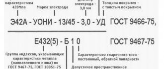
For small-scale welding operations, piece-by-piece calculation of the filler material is necessary. For example, you may need 50 welding electrodes of the UONI-13/45 brand with a diameter of 3 millimeters, of which there are 40 pieces in one kilogram. Then buying one and a half kilos will give a considerable surplus, and weighing with an accuracy of a gram will be too difficult.
By the way, it is the diameter that we need to calculate the number of filler materials in pieces, since the mass of metal deposited by one electrode in grams, which will be needed for the formula, depends on this value. We find the quantity for welding in one pass: HOP = 103ML/ME, where ME is the same melt mass of one rod in grams, which can be taken from the following table.
| Electrode brand | Electrode diameter of standard length, mm | |||
| 3,0 | 4,0 | 5,0 | 6,0 | |
| ANO-1 | — | 71,1 | 111,7 | 160,9 |
| ANO-4 | 15,4 | 35,2 | 55,3 | 79,6 |
| ANO-5 | 19,0 | 43,5 | 68,3 | — |
| ANO-b, ANO-6U | 15,4 | 35,2 | 54,9 | 78,9 |
| MR-3 | 14,7 | 33,7 | 54,1 | 77,4 |
| OZS-4 | 14,9 | 34,5 | 54,6 | 78,6 |
| OZS-6 | 19,0 | 43,5 | 68,4 | 98,5 |
| OZS-12 | 15,3 | 35,1 | 55,3 | 79,6 |
| ANO-12 | 12,1 | 27,7 | 43,5 | 62,5 |
| ANO-13 | 14,6 | 36,5 | 48,4 | — |
| ANO-29M | 15,8 | 35,7 | 55,2 | — |
| ANO-27 | 19,0 | 43,5 | 68,3 | — |
| DSK-50 | — | 41,2 | 64,7 | — |
| TMU-21U | 16,6 | 38,1 | 59,8 | — |
| TML-1U | 15,9 | 36,4 | 57,1 | — |
| ANO-TM | 16,6 | 38,1 | 59,8 | — |
| ANO-TM60 | 16,6 | 38,1 | 59,8 | — |
| ANO-10 | — | 66,7 | 104,8 | 151,1 |
| ANO-11 | 19,0 | 43,5 | 68,3 | — |
| SM-11 | — | 44,3 | 69,6 | 100,3 |
| UONI-13/45 | 16,6 | 38,1 | 59,8 | 86,2 |
| UONI-13/55 | 15,6 | 35,7 | 56,1 | 80,8 |
| UONI-13/55U | 16,6 | 38,1 | 59,8 | 86,2 |
| UONI-13/65 | 15,9 | 36,4 | 57,1 | — |
| UONI-13/85 | 17,9 | 41,1 | 64,5 | — |
| UONI-13/85U | 16,8 | 38,5 | 60,4 | — |
| OZL-8 | 14,5 | 33,2 | 52,2 | — |
| OZL-6 | 14,8 | 35,3 | 56,5 | — |
| TsL-11 | 15,6 | 35,8 | 56,3 | — |
| EA-395/9 | 14,5 | 33,2 | 52,2 | — |
| EA-981/15 | 16,3 | 37,3 | 58,5 | 84,3 |
| TsT-28 | 15,6 | 35,8 | 56,3 | 81,1 |
| TsT-15 | 14,5 | 33,2 | 52,2 | — |
| ANZHR-1 | 16,3 | 37,3 | 58,5 | 84,3 |
| ANZHR-2 | 15,6 | 35,8 | 56,3 | 81,1 |
However, often the seam has to be welded in several passes, which means that the number of consumed electrodes will increase significantly. For such compounds we use a slightly different formula, which looks like HMP = (10
3
M - m )L/ME , where m is the mass of metal from the melting of one rod during the formation of the root weld. The latter indicator is determined separately by the given welding speed and current strength: m = ( aHI )/ U , where aH is the deposition coefficient from the characteristics of the electrode, I is the current strength (A), and U is the welding speed (m/h).
This is interesting: Direct and reverse polarity when welding
Errors arising during calculations
It is almost impossible to calculate everything exactly. In any situation there will be small “disagreements” with what was originally planned. Practical methods for calculating electrode consumption are much more accurate than theoretical ones, but even with them it can be difficult to predict how the joint will turn out and how the material will behave. Errors can occur for various reasons:
- welding mode and currents;
- features of the electrodes used for work;
- welder skill, etc.
Every time you calculate the consumption of materials, you need to include an error in the final figure. The standard error value is approximately 5 - 7%. If after the work it turns out that the consumption significantly exceeded the permissible error, it means that some process violations occurred during welding.
Even if the number of consumables is calculated as accurately as possible, you need to have a small reserve to insure against defective rods.
Way to reduce costs
To improve economic performance, it is necessary to strictly implement technological rules. The qualifications of the welder are essential. To eliminate errors and inaccuracies caused by human factors, specialized automatic machines are used. Investments in the purchase of more complex equipment pay off during operation by reducing consumables consumed by 10-15%.
To reduce costs, you need to strictly follow technological rules.
Electrodes should be used only in the modes recommended by the manufacturer.
Deviations from the design current increase the consumption of materials or deteriorate the quality of the weld.
If manual technology is used, the final result largely depends on the skills of the welder. For this reason, some experts prefer a practical calculation method. By creating several control seams, you can accurately determine the material consumption under working conditions.
We recommend reading Characteristics and operation of non-consumable electrodes
How many electrodes are contained in 1 kg?
Once all the data on the required volume of materials has been received, you can begin purchasing consumables. This brings up another question: how many packs of rods should I buy? To determine this, you need to count how many rods are contained in 1 kg. A kilogram is the standard packaging of electrodes. It is important to consider all the parameters here:
- diameter;
- length;
- weight;
- packaging thickness;
The larger these parameters, the fewer electrodes in the pack. Despite all these parameters, the average weight of the electrode can be determined by its diameter. This table shows the average weight of electrodes with different, most commonly used diameters:
| Diameter, mm | Average weight, g |
| 2,5 | 17 |
| 3 | 26 |
| 4 | 57 |
| 5 | 82 |
How is the consumption per meter of seam calculated?
Many sites offer the ability to calculate electrode consumption online. This is done very simply - you need to enter a few numbers and the calculator will give you the required value.
Experienced welders prefer to calculate everything themselves. They use the following formula for this:
N = Nsv + Npr + Nright
- Nsv - welding consumption;
- Npr - expense for affixing tacks;
- Nprav - consumption for corrections carried out with idle rollers.
The rate of consumption for tack work is determined relative to the consumption for other work. With a structure thickness of up to 1.2 cm, it is 15% of the main consumption. With a thickness of more than 1.2 cm - 12%.
Peculiarities
Electrode consumption rates for welding pipelines and for other parts may differ, this must be taken into account. A complete list of standards is prescribed in regulatory documents (SNiPs, GOSTs and others). Study at least the main excerpts from the documents so that you have an idea of the restrictions.
It is also not always possible to fully comply with the standards for electrode consumption during welding work, since often working conditions do not allow performing the full range of procedures for the correct use of components. In such situations, we recommend that you carry out a calculation and at least try to get closer to this figure in your work. But if your production has strict quality control, then you still have to comply with the norms.
How is consumption calculated when welding pipes?
In theory, the calculation of this parameter is very simple. It is necessary to divide the consumption per meter of seam by the weight of one electrode. The results will show the number of rods required for the job. The number of rods must be multiplied by the footage. The resulting figure is rounded up.
To get the value in kilograms, you need to carry out the following calculations: divide the volume of the section by the density of the metal. The first parameter is the volume of the cylinder (the diameter is taken along the larger side of the joint). The resulting value must be multiplied by 1.4 - 1.8. This is a correction for cinders.
The consumption when welding pipes may differ depending on the joints being connected - the presence/absence of bevels, etc.
Ways to save materials
There are several ways to save on consumables. This will reduce the cost of purchasing rods:
- Use automatic and semi-automatic machines. When manual welding, losses of more than 5% may occur. Remember that the higher the quality of consumables and equipment, the more efficient the welding is, which means fewer losses occur.
- Different brands and models of electrodes work with different currents. When setting up the device, pay attention to this. If you select the wrong welding modes, you can suffer large losses.
- Welding technology affects consumption. So, if the rod angle is incorrect, the flow rate may increase.
Experienced welders find out in practice which welding angle is optimal. This enables them to work quickly and economically.
By adhering to such recommendations, choosing the right electrodes and carefully adjusting the equipment, you can significantly save material consumption.
We save consumables
Experienced welders are familiar with the secrets that can reduce electrode consumption. It is important here that our savings do not in any way affect the quality of work.
Here are the tips from the professionals:
- The use of semi-automatic welding equipment allows reducing the consumption of electrodes by 5-10% in comparison with the manual welding method;
- Correctly setting the welding mode on the machine will also help us control the consumption of materials. The parameters you set, such as current and voltage, must match the type of electrodes and the thickness of the metal being welded. Do not exceed the required values, especially if you use thin rods, this will significantly increase their consumption. Do not forget to check the device settings when changing electrodes.
- It is necessary to learn how to choose the correct position for welding. This skill comes with experience, and there is ample reference material for beginners.
These tips will help you reduce material consumption without risking poor results. The result will depend on your experience, not on the number of supplies used.
Expense tables
Now let's take a closer look at the tables of standard consumption values for various electrodes and types of welding.
Consumption per kilogram of deposited metal
Welding carbon and low alloy steels
Type E42
| Brand | WCC-4 | OES-23 | ANO-6 | ANO-17 | OMA-2 | VSC-4M |
| Consumption, kg | 1,6 | 1,65 | 1,7 | 1,8 | ||
Type E42A
| Brand | SSSI 13-45 | USENI 13-45A |
| Consumption, kg | 1,6 | 1,7 |
Type E46
| Brand | Consumption, kg |
| OZS-6 | 1,5 |
| ANO-13 | 1,6 |
| VRM-26 | |
| ANO-21 | 1,65 |
| ANO-4 | 1,7 |
| ANO-24 | |
| ANO-34 | |
| VRM-20 | |
| MR-3 | |
| OZS-12 |
Type E46A
| Brand | USENI 13-55K | TMU-46 |
| Consumption, kg | 1,6 | 1,65 |
Type E50
| Brand | WCC-3 | 55-U |
| Consumption, kg | 1,7 | 1,8 |
Type E50A
| Brand | Consumption, kg |
| OZS-18 | 1,5 |
| TMU-21U | |
| OZS-25 | 1,6 |
| OZS-28 | |
| OZS-33 | |
| ANO-27 | 1,65 |
| ITS-4 | 1,7 |
| SSSI 13-55 | |
| TsU-5 | |
| TsU-7 |
Type E55
| Brand | MTG-02 |
| Consumption, kg | 1,55 |
Type E60
| Brand | MTG-01K | VSF-65 | OZS-24M | SSSI 13-65 |
| Consumption, kg | 1,55 | 1,6 | ||
Welding steels with a high content of alloying components
| Brand | Consumption, kg |
| OZL-36 | 1,5 |
| ZIO-3 | 1,55 |
| EA-898/19 | 1,6 |
| OZL-14A | |
| ANV-32 | |
| EA-606/10 | 1,7 |
| TsT-15 | |
| TsT-15K | |
| TsL-11 |
Welding of corrosion-resistant steels
| Brand | OZL-8 | OZL-14 | OZL-12 | EA-400/10U | EA-400/10G |
| Consumption, kg | 1,7 | 1,75 | 1,8 | ||
Welding steels resistant to high temperatures
| Brand | Consumption, kg |
| TML-1, TML-1U, TML-3U | 1,5 |
| TsU-2M, TML-3, TsL-27A | 1,55 |
| UONI 13-15M, UONI 13-ХМ, TsL-39, TsL-36, TsL-40, TsL-17 | 1,6 |
| TsL-26M, TsL-41 | 1,65 |
| TsL-6, TsL-55, ANV-1 | 1,7 |
| TsL-10 | 1,75 |
| OZS-11 | 1,8 |
Welding of dissimilar steels
| Brand | IMET-10 | ANZHR-2 | ANZHR-1, NII-48G |
| Consumption, kg | 1,3 | 1,6 | 1,7 |
Welding of heat-resistant steels
| Brand | NIAT-5, EA-395/9 | TsT-10 |
| Consumption, kg | 1,6 | 1,7 |
Connections without beveled edges
| Seam position | Metal thickness, mm | Gap, mm | Weight of deposited metal, kg/1 m of weld |
| Lower | 1 | 0 | 0,02 |
| 1,5 | 0,5 | 0,02 | |
| 2 | 1 | 0,03 | |
| 3 | 1,5 | 0,05 | |
| 4 | 2 | 0,13 | |
| 5 | 2 | 0,16 | |
| 6 | 2,5 | 0,21 | |
| 7 | 3 | 0,28 | |
| Horizontal | 1 | 0 | 0,02 |
| 1,5 | 0,5 | 0,03 | |
| 2 | 1 | 0,04 | |
| 3 | 1,5 | 0,07 | |
| 4 | 2 | 0,17 | |
| 5 | 2,5 | 0,2 | |
| 6 | 3 | 0,25 | |
| 7 | 3 | 0,33 | |
| Ceiling | 4 | 2 | 0,08 |
| 5 | 2 | 0,13 | |
| 6 | 2,5 | 0,14 | |
| 7 | 3 | 0,16 |
Corner connections
| Options | Weight of deposited metal, kg/1 m of weld | ||||
| Metal thickness, mm | Weld section, sq. mm | ||||
| 2 | 2 | 0,03 | 0,02 | 0,03 | 0,03 |
| 3 | 4,5 | 0,05 | 0,05 | 0,05 | 0,06 |
| 4 | 8 | 0,07 | 0,07 | 0,07 | 0,08 |
| 5 | 12,5 | 0,1 | 0,11 | 0,11 | 0,13 |
| 6 | 18 | 0,15 | 0,15 | 0,16 | 0,17 |
| 7 | 24,5 | 0,2 | 0,21 | 0,22 | 0,25 |
| 8 | 32 | 0,26 | 0,27 | 0,28 | 0,32 |
| 9 | 40,5 | 0,33 | 0,34 | 0,36 | 0,4 |
| 10 | 50 | 0,4 | 0,42 | 0,44 | 0,5 |
| 11 | 60,5 | 0,49 | 0,53 | 0,57 | 0,62 |
| 12 | 72 | 0,58 | 0,62 | 0,66 | 0,73 |
| 15 | 113 | 0,91 | 0,97 | 1,04 | 1,11 |
| 18 | 162 | 1,31 | 1,37 | 1,49 | 1,6 |
| 20 | 200 | 1,62 | 1,62 | 1,78 | 1,98 |
| 22 | 242 | 1,95 | 2 | 2,16 | 2,39 |
| 25 | 323 | 2,58 | 2,6 | 2,9 | 3,18 |
T-joints
| Options | Weight of deposited metal, kg/1 m of weld | ||||
| Metal thickness, mm | Weld section, sq. mm | ||||
| 2 | 4 | 0,04 | 0,05 | 0,04 | 0,04 |
| 2,5 | 6,5 | 0,06 | 0,07 | 0,06 | 0,07 |
| 3 | 9 | 0,08 | 0,1 | 0,09 | 0,09 |
| 3,5 | 12,5 | 0,11 | 0,13 | 0,12 | 0,13 |
| 4 | 16 | 0,14 | 0,16 | 0,15 | 0,17 |
| 4,5 | 20,5 | 0,18 | 0,2 | 0,19 | 0,21 |
| 5 | 25 | 0,22 | 0,25 | 0,24 | 0,26 |
| 5,5 | 30,5 | 0,26 | 0,29 | 0,28 | 0,32 |
| 6 | 36 | 0,31 | 0,33 | 0,34 | 0,37 |
| 6,5 | 42,5 | 0,37 | 0,39 | 0,4 | 0,44 |
| 7 | 49 | 0,43 | 0,45 | 0,44 | 0,51 |
| 7,5 | 56,5 | 0,47 | 0,51 | 0,5 | 0,58 |
| 8 | 64 | 0,55 | 0,58 | 0,6 | 0,65 |
| 9 | 81 | 0,69 | 0,74 | 0,75 | 0,86 |
| 10 | 100 | 0,85 | 0,89 | 0,91 | 1,02 |
| 11 | 121 | 1,03 | 1,08 | 1,12 | 1,23 |
| 12 | 144 | 1,22 | 1,27 | 1,33 | 1,48 |
| 13 | 169 | 1,41 | 1,49 | 1,53 | 1,73 |
| 14 | 196 | 1,62 | 1,76 | 1,78 | 2,02 |
| 15 | 225 | 1,86 | 1,95 | 2,07 | 2,31 |
V-connections (one way)
| Metal thickness, mm | Gap, mm | Weight of deposited metal, kg/1 m of weld | ||||
| Seam position | ||||||
| Lower 50° | Lower 60° | Vertical 70° | Ceiling 80° | Horiz 60° | ||
| 4 | 1 | 0,09 | 0,1 | 0,132 | 0,14 | 0,11 |
| 5 | 1 | 0,13 | 0,15 | 0,19 | 0,22 | 0,16 |
| 6 | 1 | 0,17 | 0,2 | 0,29 | 0,3 | 0,24 |
| 7 | 1,5 | 0,26 | 0,3 | 0,38 | 0,44 | 0,33 |
| 8 | 1,5 | 0,31 | 0,37 | 0,47 | 0,55 | 0,44 |
| 9 | 1,5 | 0,38 | 0,44 | 0,59 | 0,69 | 0,51 |
| 10 | 2 | 0,49 | 0,57 | 0,76 | 0,86 | 0,64 |
| 11 | 2 | 0,56 | 0,66 | 0,89 | 1,02 | 0,76 |
| 12 | 2 | 0,65 | 0,77 | 1,05 | 1,23 | 0,89 |
| 14 | 2 | 0,86 | 1,02 | 1,34 | 1,6 | 1,17 |
| 15 | 2 | 0,97 | 1,15 | 1,55 | 1,81 | 1,34 |
| 16 | 2 | 1,04 | 1,23 | 1,75 | 2,02 | 1,46 |
| 18 | 2 | 1,33 | 1,6 | 2,17 | 2,51 | 1,83 |
| 20 | 2 | 1,63 | 1,94 | 2,62 | 3,11 | 2,21 |
| 25 | 2 | 2,46 | 2,94 | 4 | 4,76 | 3,34 |
First and welding pass with V-shaped connection
| Seam position | Thickness, mm | Weight of deposited metal, kg/1 m of weld | Electrode diameter, mm |
| Lower | 6-12 | 0,1 | 3 |
| Lower | more than 12 | 0,15 | 4 |
| Vertical | more than 8 | 0,15 | 3 |
| Horizontal | more than 8 | 0,15 | 3 |
| Ceiling | more than 10 | 0,1 | 3 |
Examples of formulas used
Other methods can be used for calculations.
If there is no reference data on the weight of the deposited metal, use the formula Vnm = p*S, where:
- p – specific density (7,850 kg/cubic m for carbon steel grades);
- S is the cross-sectional area that is formed when the technological process standards are observed.
The S value is taken from the table or calculated independently.
For the example discussed above, the formula S=t*z+0.75*w*h is suitable, where:
- t – thickness of parts;
- z – gap;
- w (h) – width (height) of the overlap above the joint.
Consumption coefficients by electrode type are given above for a length of 450 mm.
Different methods are used for calculations.
For other values of this parameter, the following corrections (multipliers) are applied:
- 250 mm – 1.12;
- 300 mm – 1.07;
- 350 mm – 1.04;
- 400 mm – 1.02.
When creating connections using a protective environment, the following correction factors are used:
- 1.05 – carbon dioxide (welding thick steel sheets);
- 1.15 – use of automatic and semi-automatic material feeders (CO²);
- 1.7 – creating seams with wire filled with powder filler.
Using the formula Hg=Py*L+P, the standard consumption of inert gases is determined to create a reliable protective environment. Here:
- Ru – specific norm per meter of length (L) of a welded joint;
- Рд – consumption for additional and auxiliary operations (purging, mode setting).
Recommended reading: Using SSSI electrodes
To calculate the specific value, multiply the optimal flow rate according to the rotameter (Рр) by the operating cycle time (T): Ру=Рр*T. If there are no table values, the last parameter is calculated manually using the formula T=(Vnm*60*1000)/(Kn*I), where:
- Kn – deposition coefficient;
- I is the current strength used for welding.
When creating connections, correction factors are used.
Below are the Kn values in g/Ah for different modes:
| I (A) | Wire diameter (mm) | ||
| 1,6 | 2 | 2,5 | |
| 200 | 14,2 | 12,2 | – |
| 300 | 16,5 | 13,5 | 11,1 |
| 400 | 21,1 | 16,8 | 13,9 |
| 500 | 28,3 | 22,3 | 17,8 |
When working with electrodes, use the formula T=60/V, where V is the speed of creating a welded joint. This parameter depends on the complexity of the operations performed and the method used. Structures are manually welded at a speed of up to 15-20 m/h. Using an automatic machine increases V to 100 m/h or more.
The time spent on auxiliary operations according to the standards ranges from 0.05 to 0.2 minutes when working with consumable and non-consumable electrodes, respectively. The calculated flow rate should be adjusted when welding small parts. Performing these and other complex operations increases the consumption of inert gas by 15-20%. When planning deliveries, it should be taken into account that a standard 40-liter cylinder is filled with liquid carbon dioxide (25 kg) when refilling.
Upon transition to a gaseous state, this amount forms 507 liters of a protective inert environment.
