Application of gears
The areas of application of gears are very extensive. Today, similar mechanisms are used in various industries. Studies indicate that several million copies of such products are manufactured per year. Considering the application and purpose, we note the following points:
- A spur gear is used to increase or decrease the transmitted force. Examples of their application include internal combustion engines or gearboxes, drilling and metallurgical rigs, and mining equipment.
- Bevel gears are used much less frequently. This is primarily due to the fact that they are quite complex to produce. Application area: complex mechanical transmission with variable angles and load changes. An example is the drive axles of vehicles, as well as conveyors and other devices used in the agricultural sector.
The scope of application depends on the design features of the mechanism, as well as the type of material used in production.
During operation, a monotonous moderate noise is heard. If extraneous sounds appear, this may indicate significant problems, for example, severe surface wear. Maintenance is carried out as follows:
A visual inspection is required to eliminate the possibility of cracks or chips on the surface. Particular attention is paid to ensuring that the wheels engage correctly during operation. Too much clearance can lead to excessive wear and other problems because the load is not distributed evenly
The gap is changed by adjusting the position of the shaft and bearings. At the time of work, attention is paid to ensuring that there is no end runout or other uneven movement. To determine the correct movement, marks are applied to the teeth using special paint. Until they dry completely, the shafts are turned several times. The shape of the fingerprint determines how correct the connection is. After the paint has dried, care is taken to ensure that the point of contact is in the middle of the tooth height. The position can be changed by installing special pads under the bearings. At the time of maintenance, the required amount of lubricant is added. As previously noted, without it the degree of surface wear increases significantly.
Periodic maintenance can significantly increase the service life of the device
At the time of inspection of the device, attention is also paid to the condition of the shaft, bearings and other elements that ensure stable and reliable operation. For example, a slight bend of the shaft causes increased wear on a certain part of the wheel.
In the most difficult cases, it breaks.
Geometric parameters of gears
To ensure high-quality engagement and conditions for transmitting large forces, a special gear geometry is created. It is characterized by the following features:
- The side edges are in contact when the mechanism is operating. The contact patch is provided with a special curved shape.
- The most widespread is the involute profile.
- The engagement angle is created in such a way that even with an insignificant displacement the mechanism does not jam. The parameters of the gears are indicated in the drawings.
The main transmission element can be considered gears. Let's call their main parameters the following points:
- Dividing circle. It is indicated on all drawings. This parameter refers to touching circles that roll over one another without sliding.
- The pitch of the teeth is the distance between the profile surfaces of adjacent teeth. This parameter is indicated for all gears and mechanisms in the specifications and drawings.
- Pitch length or modulus is also an important parameter to consider.
- Dividing head height.
- The tooth is an important element of every wheel. It is characterized by a fairly large number of different characteristics, among which we note the height of the stem, the tooth itself and the dividing head.
- The diameter of the circle of the peaks and valleys of the teeth.
Some of the above parameters are calculated when designing the transmission, others are selected from tabular data. Straight gears are the easiest to design and manufacture, but have less attractive performance characteristics. Torque and other parameters are selected depending on the task at hand when designing the structure.
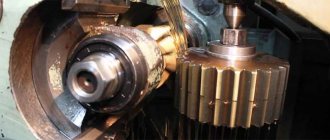
Gear production
Gears are produced on automatic lines. These highly specialized lines are divided into short and complex. The first group is associated only with cutting and finishing of gears. The second is a set of machines for various purposes, which ensure the full production of gears. In such lines, semi-automatic machines for gear processing are used, additionally equipped with loading and unloading and other automation devices.
In technological lines for the production of wheels between production machines, flexible transport connections are most often used in the form of belt and chain conveyors, as well as movable transfer carts, which eliminate the occurrence of nicks and other defects.
Helical gears
They are used most widely, since the technology for manufacturing wheel sets is relatively simple and proven. A spur gear is used to transmit torque between shafts located in parallel planes. They differ in the shape of the teeth: straight, oblique and chevron. In rare cases, when crossing shafts and minor loads, a screw profile is used.
Straight teeth are the most commonly used. They are used to transmit torque with light or medium loads, as well as in cases where there is a need to shift the wheels during operation along the shaft axis. Oblique teeth are used for smooth running. They are used for critical mechanisms and under increased loads. The chevron profile (two rows of helical teeth along the edges, arranged in a herringbone shape) is characterized by a high balance of axial displacement forces, which is a disadvantage of helical wheel pairs.
Spur gears can be of open or closed type. In the latter case, the teeth of one of the wheels are located not on the outer, but on the inner surface of the circle.
Basic linking theorem
Let's consider an involute engagement (Fig. 3.3). NN
– the common normal of two involutes for both is a generating line, thus, in all phases of engagement, the point of contact lies on the straight line
NN
, therefore the line
NN
is called
the engagement line
.
the line connecting the centers of the wheels is called the engagement angle W.
Point “ W ”
The intersection of the engagement line and the line connecting the centers of the wheels is called
engagement pole
.
It can be seen that during all phases of engagement the pole remains in place. The section of the engagement line P 1 P 2
enclosed between the circles of the tooth heads is called
the active section
of the engagement line.
Let us draw the velocity vectors of points M (M 1
;
M 2 )
engagements
V 1
and
V 2
(they are drawn perpendicular to their radii - vectors at point
M
).
From the diagram of the expansion in the rectangular coordinate system of the velocities V 1
and
V 2
it is clear that normal operation of the gearing is possible only when
V n1 = V n2
:
;
.
Where
or
,
i.e. the first condition is satisfied.
The last equality is called the main linking theorem. This theorem can be formulated as follows: the normal at the point of contact of the elements of the higher rolling and sliding pair divides the line of centers into parts inversely proportional to the angular velocities.
It is important to note that at point W there is no mutual sliding of the teeth, i.e.
.
This means that in the process of engagement of a circle with diameters d W1
and
d W2
run in without slipping.
These circles are called initial
.
From the similarity it follows that. This implies an important relationship
The force in the engagement is directed along the general normal, that is, along the line of engagement, and, therefore, is constant in direction (second condition).
Bevel gear
In conditions where torque from the source to the consuming node must be delivered with an angular displacement, intersecting shafts are used. Their axes are most often at an angle of 90 degrees. In such cases, bevel gears are usually used.
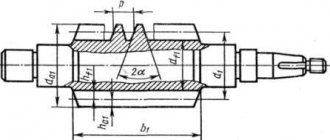
It is called so because of the design features of the gear pairs. They have the shape of a cut cone and are mated with their lateral planes, on which the teeth are cut. In profile, they are higher at the base and decrease towards the top.
The ring gear can have a straight, tangential or curved cut. If the profile is made in the form of a helical spiral, and the shafts, in addition to intersection, also have an axial displacement, then such a bevel gear is called hypoid. It has a smooth running and low noise level, but has an increased tendency to jam, so special lubricants are used for it.
Compared to spur gears, bevel gears can provide only 85% of their load-bearing capacity. In terms of manufacturing and assembly technology, they are the most complex. However, the ability to transmit torque with angular displacement makes them indispensable in complex units and mechanisms.
Business and finance
BanksWealth and welfareCorruption (Crime)MarketingManagementInvestmentSecuritiesManagementOpen joint-stock companiesProjectsDocumentsSecurities - controlSecurities - valuationsBondsDebtCurrencyReal estate (Rent)ProfessionsWorkTradeServicesFinanceInsuranceBudgetFinancial servicesCreditsCompaniesState-owned enterprisesEconomyMacroeconomicsMicro EconomicsTaxesAuditMetallurgyOilAgricultureEnergyArchitectureInteriorFloors and ceilingsConstruction processBuilding materialsThermal insulationExteriorOrganization and production management
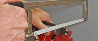
Processing methods
Gears are made from stamped or cast blanks by cutting teeth . Cutting is done using copying and rolling methods. Running allows you to cut teeth of various configurations with one tool. Cutting tools can be cutters, hobs or slats. For cutting using the copying method, finger cutters are used. Heat treatment is carried out after cutting, but for high-precision gearing, grinding or rolling is also used after heat treatment.
reference Information
DocumentsLawsNoticesDocument approvalsContractsRequests for proposalsTechnical specificationsDevelopment plansDocument managementAnalyticsEventsCompetitionsResultsCity administrationsOrdersContractsExecution of workProtocols for consideration of applicationsAuctionsProjectsProtocolsBudget organizationsMunicipalitiesRegionsEducationsProgramsReports
by mentionsDocumentary baseSecurities
Regulations
Financial documents
Resolutions
Categories by topicFinancecities of the Russian Federationregions by exact datesRegulations
Terms
Scientific terminologyFinancialEconomic
Time
Dates20152016Documents in the financial spherein the investment sphere
Design features and principle of operation
A gear train is a mechanism in which motor energy is transferred between shafts through the interaction of gear wheels and racks.
The wheel on the shaft transmitting rotation is called the driving one, and the one on the one that receives energy is called the driven one. In this case, the larger part of the pair is called the wheel itself, and the smaller part is called the gear. The entire structure is often called a wheelset.
The interaction of the tandem elements is that the head of the wheel tooth enters the cavity of the gear, thereby causing it to rotate. As a rule, the rotation of the latter occurs in the direction opposite to the movement of the wheel.
There is a minimum gap between the elements, which allows lubrication, improving rotation and preventing jamming.
Starting a car with an automatic transmission
An automatic transmission requires protection against incorrect starting, so such protection was immediately invented in tandem with the gearbox. If you don’t know how to properly start a car with an automatic transmission and this is your first time behind the wheel, you will struggle with the ignition.
Traditionally, starting an engine with an automatic transmission occurs as follows.
- The speed selector must be set to parking mode (P).
- Squeeze the brake pedal, do not release it, and start starting the engine.
- Insert the key into the lock and turn it until you hear a click. At this stage, the fuel pump starts and the indicators on the dashboard light up (read how to open a car door without a key).
- Turn the ignition key when the lights go out until the starter starts. Release the key and it will return to its original position.
- If the engine refuses to start, you can make a couple more attempts at intervals of half a minute.
- Move the selector to position D or R, taking into account the desired direction of travel, after the gearbox has warmed up. Start driving after releasing the brake pedal.
Warming up the engine after starting is a mandatory step, since it ensures normal operation of the engine lubrication system. This is explained by the fact that the oil mist necessary to lubricate the cylinders and pistons does not form immediately.
Warm up the car while idling. In this case, the number of engine revolutions should be slightly higher than idle speed.
Types of motion transmission
The engine that generates energy and the final unit that consumes it often differ in characteristics such as rotation speed, power, and angle of application of force. In addition, one source of rotational energy can be used to drive several different components or assemblies at once. To ensure the delivery of torque under such conditions, intermediate modules are needed that would transmit this force with minimal losses.
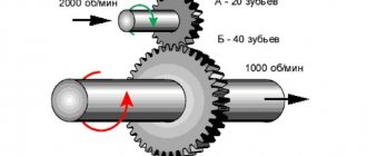
If, as a result of such distribution or transformation, the revolutions of the drive shaft become greater than those of the driven shaft, then it is customary to talk about a reduction gear. In this case, the loss of speed is compensated by an increase in the load on the driven axle and an increase in the power of the consuming node. In the case where an increase in the number of revolutions is ultimately observed, such a gear will be an overdrive. Accordingly, this will be accompanied by a decrease in force on the driven shaft.
Main types of gears
All types of gears are actively used in various fields of industry and instrument making. Every year, such mechanisms are produced in millions of batches. The scope of their use is so vast that finding a device that uses rotational motion without the help of gear joints is quite problematic.
According to their design, gears are divided into the following categories:
- Cylindrical. It is used most often, as it has a simpler gear production technology compared to other types. A spur gear is used to transmit torque between shafts that are in parallel planes. It can have several tooth shapes: straight, oblique and chevron. This type of gear has found its application in internal combustion engines, gearboxes of rolling stock, machine tools, and drills. It is widely used in metallurgy, mechanical engineering and other industries.
- Conical. It got its name due to the unusual design of the wheel pairs. It has the shape of a cut cone with teeth cut on it. The size of the tooth profile decreases from the base to the top. Bevel gears are used in complex and combined mechanisms, which are characterized by frequent changes in loads and rotation angles. Examples include drive axles of vehicles, agricultural machinery or trains, and drives of various industrial machines.
- Rack and pinion. Used to convert rotational motion into translational motion and vice versa. In this case, one of the gears is replaced by a plane with cut teeth. Rack and pinion transmission is easy to manufacture and install, and can withstand significant loads. It is mainly used in the mechanism of machines based on translational motion: presses, conveyors with alternating feed, steering control mechanisms in front-wheel drive cars.
Any type of gear transmission is characterized by a long operating period and reliable operation (subject to a certain load level and timely maintenance). A relatively small mechanism is capable of providing high efficiency, which is why it is used for a wide range of tasks.
Drawing
Gear transmission is a mechanism that serves to transmit rotational motion from one shaft to another and change the rotation speed through gears and racks.The gear wheel sitting on the shaft transmitting rotation is called the driving one, and on the shaft receiving rotation is called the driven one. The smaller of the two wheels of a mating pair is called a pinion; the larger one is a wheel; the term "gear" refers to both parts of the transmission.
Gears are the most common type of transmission in modern mechanical engineering. They are very reliable in operation, ensure a constant gear ratio, are compact, have high efficiency, are easy to operate, durable and can transmit any power (up to 36 thousand kW).
The disadvantages of gear drives include: the need for high precision manufacturing and installation, noise when working at high speeds, and the impossibility of continuously changing the gear ratio.
Due to the variety of operating conditions, the shapes of gear elements and gear designs are very diverse.
Gears are classified according to the characteristics given below.
- According to the relative position of the wheel axes : with parallel axes (cylindrical gear - Fig. 172, I-IV); with intersecting axes (bevel gear - Fig. 172, V, VI); with crossing axes (screw gear - Fig. 172, VII; worm gear - Fig. 172, VIII).
- Depending on the relative rotation of the wheels and the arrangement of the teeth, gears with external and internal gearing are distinguished. In the first case (Fig. 172, I-III) the wheels rotate in opposite directions, in the second (Fig. 172, IV) - in the same direction. The rack and pinion transmission (Fig. 172, IX) serves to convert rotational motion into translational motion.
- Based on the shape of the profile, teeth are distinguished between involute (Fig. 172, I, II) and non-involute, for example, a Novikov cylindrical gear, the teeth of the wheels of which are outlined by circular arcs.
- Depending on the location of the theoretical tooth line, wheels with straight teeth (Fig. 173, I), oblique (Fig. 173, II), chevron (Fig. 173, III) and helical (Fig. 173, IV) are distinguished. In non-spur gears, smooth operation increases, wear and noise are reduced. Due to this, spur gears are mostly used in installations that require high peripheral speeds and high power transmission.
- Based on their design, a distinction is made between closed gears, housed in a special impenetrable housing and provided with constant lubrication from an oil bath, and open gears, operating without lubrication or periodically lubricated with grease (Fig. 174).
- Based on the peripheral speed, they are distinguished: low-speed gears (v equal to 3 m/s), medium-speed (v equal to 3... 15 m/s) and high-speed (v more than 15 m/s).
Rice. 172
Rice. 173
Rice. 174
Basics of gear theory
The side faces of the teeth, which come into contact with each other during the rotation of the wheels, have a special curved shape called a tooth profile. The most common in mechanical engineering is the involute profile (Fig. 175).
Rice. 175
Giving the tooth profiles of gears such shapes is not an accident. In order for the teeth of two meshed wheels to roll smoothly over one another, it was necessary to choose a profile for the teeth that would not cause distortions and pinching of the head of one tooth in the cavity of another.
In Fig. 176 shows a pair of gears in mesh. The line connecting the centers of wheels O1 and O2 is called the center line or the center distance - aw.
Rice. 176
The point P of tangency of the initial circles dW1 and dW2 - the pole - always lies on the line of centers. Initial circles are those that touch each other at the meshing pole, have common centers with the gears and roll over one another without slipping.
If you follow the movement of a pair of teeth of two wheels from the moment they first touch each other until the moment they disengage, it turns out that all points of contact during the movement will lie on the same straight line NN. The straight line NN passing through the gearing pole P and tangent to the main* circles db1, db2 of two conjugate wheels is called the gearing line . The segment ga of the engagement line, cut off by the circles of the protrusions of the mating wheels, is the active part of the engagement line, which determines the beginning and end of the engagement of a pair of mating teeth.
The engagement line is the pressure line of the mating tooth profiles during operation of the gear train.
The angle ?w between the line of engagement and the perpendicular to the line of centers O1O2 is called the angle of engagement. The basis for profiling involute teeth and the tool for cutting them is the initial contour of the so-called rack, standard according to GOST 13755-81, equal to 20°.
During operation of a cylindrical spur gear, the pressure force Pn of the drive gear O1 at the beginning of engagement is transmitted by the tooth leg to the mating side surface (contact line) of the head of the driven wheel O2. The more a pair of teeth are in mesh at the same time, the smoother the transmission operates, the less load each tooth takes on itself.
The desire to make a gear transmission more compact makes it necessary to use gears with as few teeth as possible. Changing the number of teeth on a gear affects their shape (Fig. 177). As the number of teeth increases to infinity, the wheel turns into a rack and the tooth acquires a rectilinear shape. With a decrease in the number of teeth, the thickness of the tooth at the base and apex simultaneously decreases, and the curvature of the involute profile also increases, which leads to a decrease in the bending strength of the tooth. When the number of teeth is reduced, when z < zmim, the so-called cutting of teeth occurs, that is, the phenomenon when the teeth of a large wheel, when rotating, enter the area of the leg of a smaller wheel (see the shaded area in Fig. 177), thereby weakening the tooth in the most dangerous section, increasing tooth wear and reducing transmission efficiency.
Rice. 177
In practice, tooth undercutting is prevented primarily by selecting the appropriate number of teeth. The smallest number of teeth (zmin), at which cutting does not yet occur, is recommended to be selected from 35 to 40 at 15° and from 18 to 25 at ?w equal to 20°.
In some cases, it is necessary to carry out a transmission with a number of teeth less than recommended, and in this case a correction is made, or, as they say, the shape of the teeth is corrected. One of these methods is to change the height of the head and stem of the tooth to ha = 0.8m; hf = m. This method eliminates trimming, but increases tooth wear.
Now let's turn to the presentation of the main theorem of engagement: the general normal (engagement line NN) to the conjugate tooth profiles divides the interaxial distance (?w= О1О2) into segments (О1Р and 02Р), inversely proportional to the angular velocities (w1 and w2). If the position of point P (engagement pole) is constant at any moment of engagement, then the gear ratio - the ratio of the speed of rotation of the drive wheel to the speed of rotation of the driven wheel - will be constant.
02Р / O1P = w1/w2 = i = const.
4.3. Basic elements of gears. When the axial distance ?w = О1О2 of a pair of gears changes, the position of the engagement pole P on the line of centers will also change, and, consequently, the size of the diameters of the initial circles, that is, a pair of mating gears can have an infinite number of initial circles. It should be noted that the concept of initial circles refers only to a pair of mating gears. For a single gear, we cannot talk about the initial circle.
If you replace one of the wheels with a gear rack, then for each gear there is only one circle that rolls along the initial straight rack without slipping - this circle is called the dividing circle .
Note. This book deals with gears in which the initial and pitch circles coincide.
Since each gear has only one pitch circle, it is the basis for determining the main parameters
gear transmission according to GOST 16530-83 and GOST 16531-83 (Fig. 178)
Rice. 178
Main parameters of gears:
1. The pitch circles of a pair of gears are contiguous circles that roll over one another without sliding. These circles, being in engagement (in transmission), are conjugate. In the drawings, the diameter of the pitch circle is designated by the letter d.
2. The circumferential pitch of the teeth Pt is the distance (mm) between the same profile surfaces of adjacent teeth. The pitch of the teeth, as is easy to imagine, is equal to the pitch circle divided by the number of teeth z.
3. Length of the pitch circle. Module. The length of the pitch circle can be expressed through the diameter and number of teeth: Pd = Pt • r. Hence the diameter of the pitch circle d = (Pt • z)/P.
The ratio Pt/P is called the gearing module and is denoted by the letter m. Then the diameter of the pitch circle can be expressed through the module and number of teeth d = m • z. Hence m = d/z.
The module value for all gears is a standardized value.
To understand the relationship between the values of Pt t and d, a diagram is shown in Fig. 178, II, which conventionally shows the placement of all teeth 2 of the wheel along the diameter of its pitch circle in the form of a gear rack.
4. The height of the pitch head of the tooth ha is the distance between the pitch circle of the wheel and the circle of the tops of the teeth.
5. The height of the tooth pitch hf is the distance between the pitch circle of the wheel and the circle of the depressions.
6. Tooth height h - the distance between the circles of the tops of the teeth and the cavities of a cylindrical gear h = ha + hf..
7. The diameter of the circle of the tops of the teeth da is the diameter of the circle limiting the tops of the heads of the teeth.
8. The diameter of the circle of the tooth cavities df is the diameter of the circle passing through the bases of the tooth cavities.
When designing a mechanism, the designer calculates the value of the module t for the gear transmission and, rounding, selects the module according to a table of standardized values. He then determines the values of the remaining geometric elements of the gear.
Gear transmissions with M.L. gearing Novikova
In this gearing, the profile of the teeth is not made along an involute, but along a circular arc or along a curve close to it (Fig. 179).
Rice. 179
When engaged, the convex teeth of one of the wheels contact the concave teeth of the other. Therefore, the area of contact of one tooth with another in a Novikov gear is much larger than in involute gears. The contact of conjugate profiles theoretically occurs at a point, therefore this type of engagement is called point .
With the same parameters as involute gearing, a point engagement system with a circular tooth profile provides an increase in contact strength, which in turn makes it possible to increase the load capacity of the transmission by 2...3 times compared to an involute gear. The interaction of the teeth in the compared gears is also different: sliding predominates in the involute gearing, and rolling predominates in the Novikov gearing. This creates favorable conditions for increasing the oil layer between the teeth, reducing friction losses and increasing resistance to galling.
The advantages of the Novikov gearing include the possibility of using it in all types of gears: with parallel, intersecting and crossing wheel axes, with external and internal gearing, constant and variable gear ratios. Friction losses in this gearing system are approximately 2 times less than losses in involute gearing, which increases transmission efficiency.
The main disadvantages of gears with Novikov gears include: the technological complexity of manufacturing wheels, the width of the wheels must be at least 6 modules, etc. Currently, gears with Novikov gears are used in large gearboxes.
general description
In order to transfer forces, previously only one method was used everywhere - a belt, which had an important intermediate link - a belt. In our case, the method changes
The unnecessary adapter is eliminated, and instead there is adhesion between the elements.
In this way, not only does the level of reliability increase and the size of the entire system is minimized, but another important advantage is also achieved. Reduces the energy required to activate the entire structure
There are a lot of key factors that determine the effectiveness and scope of the mechanism. Of course, dimensions, production material and accuracy become important aspects.
If we talk about general information about gears, you need to know that in a good product there is always a gap between the teeth. They are not located closely. Otherwise, sliding will be impossible by definition. It will also be extremely inconvenient to lubricate moving parts. The service life, as well as the efficiency of application, will be significantly reduced. We must not forget that many types of production involve the formation of high temperatures at production sites. And the mechanical parts themselves heat up during operation due to the banal force of friction. This means that the metal will expand and increase slightly in size. And without clearance, the teeth will simply stand up, resting against each other and blocking further movement.
Therefore, the choice of the final product should always be based on something that will definitely not let you down. That is why we always pay attention to details. And any part of our machines and other products meets not only all the requirements of regulatory documentation, but also the wishes of our customers.
Application
All types of gears are widely used in various industrial sectors. The annual production of various wheel sets is in the millions. The scope of their application is so vast that a rare device, mechanism or unit that uses rotational motion in its work does not include one or another type of gear movable connection.
A spur gear is used to convert rotary motion with a reduction or increase ratio. Examples: internal combustion engines, gearboxes in rolling stock, machine tool construction, drilling, metallurgical, mining and all types of industry.
Bevel gears are used to a lesser extent due to the complexity of the wheel set manufacturing process. It is used in complex and combined mechanisms where there is rotational motion with variable angles and changing loads. Specialty gearboxes typically use bevel gears. Examples: drive axles of cars, agricultural machinery, locomotives, wheel sets of conveyors, drives of various industrial equipment.
How to start a car if the battery is dead
Here I will talk about all the ways to start a vehicle on a half-dead battery. But some apply only to a vehicle with a manual transmission.
Lighting up
If you don’t know how to start a car with an automatic transmission with a dead battery, or are in doubt, then the only correct solution is to light it from another vehicle.
- Place two vehicles parallel to each other. Turn off the ignition on both.
- Connect the cigarette lighter terminals of the battery of the working vehicle and the one you want to start.
- Start the donor engine.
- Turn on the heated windows, radio - everything to reduce the load when disconnecting.
- Disconnect the negative wire from the terminal on the donor, then on the car from which it is lit. Then remove the positive terminal.
Proceed strictly according to the instructions. Otherwise, you can burn the starter and fuses.
Push launch
I do not recommend starting the vehicle with an automatic transmission using a pushrod. Although experienced car owners say that in mode n, for example, neutral is possible.
There is no direct contact between the engines and the wheels. All systems are down. When you stop suddenly, the machine takes the blow. After this method, the automatic transmission cannot be restored.
Starting using a ROM jumper charger
There are many designs and variations of ROM for starting a car with an automatic transmission:
- pulse;
- transformer;
- capacitor.
My advice is to purchase a pulse charger. With a shallow discharge, it will be enough to start the engine. And in deep conditions, you will have to wait a little while the battery is recharged. And the device itself is compact and will fit into the glove compartment of an automatic vehicle.
Starting with booster or lithium-ion battery
One type of ROM is boosters. These are a kind of power banks for car batteries. They supplement the battery with their charge and thereby help start the car. The best choice.
If your battery runs out in the wilderness, and you don’t know what to do or where to look for help, then having a charged booster in the glove compartment will bring the battery back to normal.
Start with fast charge
This type of launch is not always possible. It all depends on the condition of the car’s battery on the automatic transmission and the weather on the street where the car is parked. You can start with a quick charge only if there is absolutely nothing left.
Its essence lies in recharging with two ordinary single-core wires from the car, which is the cigarette lighter. There is a similarity to lighting a cigarette. But instead of the donor, the car starts and lights a cigarette. After ten minutes of operation it turns off.
Experts explain this method by the capacitor effect. The battery is charged just enough to start the engine the first time. More than that won't be enough. And it may lose capacity.
Starting a car using a strap
I am often asked how to start a car with an automatic transmission using the sling method. That is, spin the crankshaft and transmission shaft manually on a raised wheel.
This method is not suitable for cars with automatic transmission, but is ideal for cars with manual transmission.
Starting a car using a crooked starter
This method is ideal for those who have a dead battery in an old car. Modern vehicles with automatic transmissions do not have a hole under the starter curve.
Starting with alcohol
Another type of starting the starter on a vehicle with an automatic transmission if the battery is dead is called “drunk”. You can start the battery in this way only if it is dismountable. Pour white or red wine into the electrolyte containers and turn on the ignition.
A chemical reaction will begin. The voltage will increase and the engine will start.
Service
During normal operation, the gear mechanism operates smoothly, and the process is accompanied by monotonous moderate noise. The presence of extraneous sounds and uneven rotation indicate wear of the engaging surfaces or a violation of the adjustment.
During maintenance, inspection checks for cracks, broken teeth or chipped teeth. Particular attention is paid to the correct engagement of the wheel pairs and the absence of gaps. During operation, check the end runout and control the friction surfaces.
Correct engagement is determined by applying paint to the gear teeth. Until it dries, the shafts are turned several times and the places where the working surfaces come into contact are inspected. The shape of the print (it must be in the shape of an ellipse) determines the general condition of the transmission.
Pay attention to the touch points. They should be approximately in the middle of the tooth height. The paint spot should occupy 70–80% of its length. Adjustment basically comes down to increasing or decreasing the thickness of the spacers under the bearings.
Depending on the type of unit, lubrication of the open mechanism can be carried out periodically manually with plastic material. For closed structures, it is carried out by force by spraying or dipping part of the impeller crown into a bath of lubricant.
Types of gears
As already mentioned, gears (gearing transmissions) make it possible to effectively transmit the rotational motion that comes from the engine.
At the same time, the movement is transformed, the rotation speed, the magnitude of the torque, the direction of the axes of rotation, etc. change. To perform such tasks, there are different types of gears. First of all, they are usually classified according to the peculiarities of the location of the axes of rotation.
- Cylindrical gear. Such a gear consists of a pair, which usually has a different number of teeth, and the axes of the spur gear gears are parallel. Also, the ratio of the number of teeth is usually called the gear ratio. The smaller gear is called a pinion, while the larger one is called a gear.
Gears can be externally or internally geared. If everything is clear with the external gear (in this case, the gear scheme assumes that the teeth are located on top), then with internal gearing, the teeth of the larger wheel are located on the inner surface. Also, rotation is only possible in one direction.
Having considered the main types of gears (gears) above, it should be added that these types can be used in different combinations, taking into account the characteristics of certain kinematic schemes.
Gear drives may also differ in tooth shape, profile and type. Taking into account the differences, it is customary to distinguish the following gears: involute, circular and cycloidal. In this case, involute gears are most often used, since technologically this solution is superior to other analogues.
First of all, such teeth are cut using a simple rack and pinion tool. This gearing has a constant gear ratio, which does not depend in any way on the degree of displacement of the center-to-center distance. The only disadvantage of gearing is that during the transmission of high power there is a small contact patch in the two convex surfaces of the teeth. The result is surface destruction and other material defects.
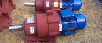
Gear design
The classic gear design has been used for a long time. The design in question has the following features:
- The body is used as the basis. It is often made from cast iron or other corrosion-resistant steels. The housing provides reliable fastening of the main elements and also serves as a container for lubricant. There is simply a huge number of different cases, it all depends on the area of application of the mechanism.
- The main element is the shaft, which transmits rotation through gearing. As a rule, the shaft receives rotation from an electric drive or other elements. Bearings are installed to secure them. The shaft is matched to the mounting hole of the gears and can have a stepped shape.
- The gears are mounted on the shafts using the pressing method. Due to this, the possibility of turning elements that are engaged is eliminated. In addition, fixation is ensured by a key.
- The distance between the gear shafts is selected taking into account the diameter of the wheels, as well as their other parameters.
- The shape of the gears may vary significantly. Often the side has small protrusions, and the working surface is represented by a combination of teeth. The number of teeth, their direction and many other parameters may differ significantly. Characteristics are selected depending on the area of application of the mechanism.
In general, we can say that the device in question is quite simple, which ensures a long service life. A type of gear transmission is also a screw mechanism or rack. Today, if necessary, a drawing of a screw drive can be obtained from the Internet.
Gear drives are classified according to a fairly large number of different characteristics. Only with the correct selection of the most suitable design option can a long service life and the required characteristics be ensured.
Flaws
Gear drives also have a number of features that can be attributed to their disadvantages. In terms of operation, such a mechanism is noisy at high rotation speeds. It cannot respond flexibly to changing loads, as it is a rigid structure with precise adjustment.
In technological terms, this is the complexity of manufacturing pairs of gear wheels. This type of gear requires increased precision, since the teeth mesh under a constantly changing voltage. Under such conditions, fatigue failure of the material is possible.
This occurs when the permissible loads are exceeded. The teeth may become chipped or partially or completely break. The broken fragments get into the mechanism, damage the adjacent mating areas, which leads to jamming and failure of the entire assembly.
The most widely used type is the cylindrical gear drive. It is used in units and mechanisms with parallel shafts. According to their design features, teeth with straight, oblique and chevron profiles are distinguished.
For intersecting shafts, a worm or helical cylindrical gear is used, and for intersecting shafts, a bevel gear is used. A rack and pinion transmission differs in that the gear in a common pair mechanism is replaced by a working plane. At the same time, teeth are cut on it, identical in profile to the wheel. As a result, the rotational motion is converted into translational motion.
Gears are also divided by rotation speed: low-speed, medium and high-speed. According to their purpose, they are divided into power and kinematic (not transmitting significant power). In addition, gears can be classified according to the gear ratio, axle mobility (ordinary and planetary), the number of degrees, meshing accuracy (12 classes), and manufacturing method. The shape of the tooth profile can be involute, cycloidal, lantern, or circular.
Main settings
To ensure mobility and operability, the design of individual parts of the mechanical transmission must be consistent in size and geometry. For this purpose, when describing such devices, it is customary to use a system of special parameters. These include geometric, weight, size and strength values, fixed by standards. The use of standard parameters makes it relatively easy to calculate standardized gears and ensures guaranteed interfacing of all products with each other. Naturally, for different types, the parameters will be slightly different. The following discusses the terms associated with the design of an involute cylindrical wheel. These parameters, for the most part, describe the main characteristics of other wheel options.
The tooth section of most gears is based on an involute profile, which is obtained on the basis of the curve of the same name. Its use is easily standardized, characterized by high manufacturability and low requirements for the assembly quality of the mechanism. The main parameters of an involute gear are the engagement module and the number of gear teeth. With the same outer diameter of the parts, the values of these quantities can differ significantly in different design options.
The number of teeth determines the gear ratio and the geometric dimensions of the teeth. On the drive wheel of the gearbox it is smaller than on the driven wheel. As a result, one normal revolution of the drive gear leads to the rotation of the driven wheel only at a certain angle. The ratio of the number of teeth of two wheels gives the value of the gear ratio. The size of the teeth is determined as the ratio of their number to the circumference of the wheel. In order to simplify calculations and guarantee engagement between different wheels, an additional parameter is provided, called the engagement module. Any gears with the same module ensure interaction with each other and can be used to build mechanisms, without additional processing.
The sum of the tooth width and root width together gives the pitch of the gear. Taking into account the unevenness of the profile along the radius and the dependence of the arc length on the diameter, an infinite number of values of this parameter can be determined in each wheel. For the purpose of standardization, it is customary to consider a step along a pitch circle, also called a circular step. The ratio of this step to pi gives the engagement modulus. In some cases, angular pitch, measured in degrees, is used to describe gears. The standards also provide for several other angular values. For example, to simplify equipment setup when making wheels, the angular width of the tooth and the angular width of the cavity are considered. They are also determined on the basis of the dividing circle.
What are gears and gears made of?
Typically, the core of a gear is steel. In this case, the gear must have greater strength, since the wheels themselves may have different strength characteristics.
For this reason, gears are made from different materials, and such products also undergo additional heat treatment and/or complex chemical and temperature treatment.
For example, gears that are made of alloy steel also undergo a surface hardening process, which may use a method to achieve the desired characteristics (nitriding, carburizing, or cyanidation). If carbon steel is used to make a gear, such material is case hardened.
As for the teeth, surface strength is extremely important for them, and the core must be soft and viscous. These characteristics allow you to avoid fracture and rapid wear of the working loaded surface. Let us also add that the wheel pairs of mechanisms where there are no heavy loads and high rotation speeds are made of cast iron. You can also find bronze, brass and even all kinds of plastic as materials for making wheelsets.
The gears themselves are made from a blank obtained by casting or stamping. Then the tooth cutting method is applied. Cutting is carried out by using copying and rolling methods. The rolling method makes it possible to produce teeth of different configurations using one tool (cutter, hobs, rack).
To carry out cutting using the copying method, finger cutters are required. After cutting, heat treatment is performed. If high-precision gearing is required, after such heat treatment additional grinding and rolling are performed.
Manufacturing of gears
There are several methods for making wheels.
Running method
Currently, it is the most technologically advanced, and therefore the most widespread, method of manufacturing gears. In the manufacture of gears, tools such as a comb, hob cutter and cutter can be used.
Rolling method using a comb
Manufacturing of gears. Making a gear wheel.
A cutting tool shaped like a rack is called a comb. On one side of the comb, the cutting edge is sharpened along the contour of its teeth.
The rolling wheel blank performs a rotational movement around its axis. The comb makes complex movements, consisting of a translational movement perpendicular to the wheel axis and a reciprocating movement (not shown in the animation) parallel to the wheel axis to remove chips across the entire width of its rim. The relative motion of the comb and the workpiece can be different, for example, the workpiece can perform an intermittent complex rolling movement, coordinated with the cutting movement of the comb.
The workpiece and the tool move relative to each other on the machine as if the profile of the cut teeth is engaged with the original producing contour of the comb.
Rolling method using a hob cutter
In addition to the comb, a hob cutter is used as a cutting tool. In this case, a worm gear occurs between the workpiece and the cutter.
Rolling method using a cutter
Gears are also chiseled on gear shaping machines using special cutters.
A gear shaper is a gear wheel equipped with cutting edges. Since it is usually impossible to cut off the entire metal layer at once, processing is carried out in several stages.
During processing, the tool makes a reciprocating movement relative to the workpiece. After each double stroke, the workpiece and the tool rotate relative to their axes by one step. Thus, the tool and the workpiece seem to “run” against each other. After the workpiece has made a full revolution, the cutter makes a feed motion towards the workpiece. This process continues until the entire required layer of metal is removed.
Casting mold for a bronze ratchet wheel (China, Han Dynasty. (206 BC - 220 AD)).
Copy method (Divide method)
A disc or finger cutter is used to cut one tooth cavity of the gear. The cutting edge of the tool is shaped like this depression. After cutting one cavity, the workpiece is rotated one angular step using a dividing device, and the cutting operation is repeated.
The method was used at the beginning of the 20th century. The disadvantage of this method is its low accuracy: the cavities of a wheel made using this method are very different from each other.
Hot and cold rolling
The process is based on the sequential deformation of a layer of a workpiece heated to a plastic state at a certain depth using a gear-rolling tool. This combines induction heating of the surface layer of the workpiece to a certain depth, plastic deformation of the heated layer of the workpiece to form teeth, and rolling of the formed teeth to obtain a given shape and accuracy.
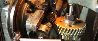
Manufacturing of bevel wheels
The manufacturing technology of bevel wheels is closely related to the geometry of the side surfaces and tooth profiles.
The method of copying the shaped profile of a tool to form a profile on a bevel wheel cannot be used, since the dimensions of the cavity of the bevel wheel change as it approaches the apex of the cone. In this regard, tools such as a modular disc cutter, a finger cutter, or a shaped grinding wheel can only be used for rough cutting of dimples or for the formation of wheel dimples no higher than the eighth degree of accuracy.
To cut more precise bevel wheels, use the method of running in the machine engagement of the cut workpiece with an imaginary producing wheel. The side surfaces of the producing wheel are formed due to the movement of the cutting edges of the tool during the main cutting movement, which ensures cutting off the allowance. Tools with a straight blade became more widespread. With a straight main movement, a straight blade forms a flat producing surface. Such a surface cannot form an involute conical surface with spherical involute profiles. The resulting conjugate conical surfaces, which differ from involute surfaces, are called quasi-involute.
Modeling
Materials
In mechanical engineering, gears also perform power functions: the load on the teeth can amount to tons. Typically, the manufacture of gears involves the use of steel. Softer steel can be used to make bearings and shafts. For the manufacture of wheels, the most rigid steel is taken, since they are subject to maximum load. Typically, gear materials are not just alloy or carbon steel, but also special processing methods - nitriding, surface level hardening, cementing.
In the middle, the holds are made softer than on the surface. If the teeth are equally hard throughout their entire volume, then under constant loads they will begin to break and become brittle. This cannot be allowed.
Therefore, after manufacturing, each part undergoes additional thermal hardening. In most cases, heat treatment is enough to increase the reliability of parts, but when manufacturing parts for use in high-precision devices, additional processing of gears is required - grinding.
Practical use
With the development of industry, gears have been widely used in a variety of industries: from large-sized units (electric turbines) to small household appliances (watches and various measuring instruments).
Among the largest consumers of wheelsets:
- mechanical engineering (ICE);
- mining industry (drilling equipment);
- metallurgy.
Similar elements are no less actively used in the creation of household appliances for various purposes. One of the simplest and most striking examples is a clock mechanism driven by wheelsets.
Tooth shape and characteristics
The main factor of the wheel in a gear train is the gears or teeth. The teeth are divided into:
- straight without deviations along the axle: such wheels are used everywhere.
- oblique: greatly improve the level of adhesion, but worsen efficiency and service life;
- chevron ones allow you to reduce the load on the bearing. Since the axes do not put pressure on the element, this is beneficial during long-term operation;
internal ones - they operate almost silently and function perfectly in bending.
Advantages and disadvantages
The appearance of gears is an evolutionary step in the production of gears, so there is no point in disputing their merits. All the advantages of such mechanisms are striking:
- the long service life is explained by the simplicity of the mechanism, the absence of brittle parts, the strength of the metal used in the manufacture of parts and the presence of a hardened part that comes into contact with the teeth of the partner gear;
- simple speed adjustment, depending on installation, settings, etc.;
- high level of efficiency;
- Compactness is the most important advantage, since the small size of the unit allows you to save space, and ultimately make the final mechanism itself more compact.
There are, of course, certain disadvantages:
- You won’t be able to change the pace while working;
- It will not be possible to make a mechanism in a garage using a makeshift method, such as a clutch;
- presence of noise: the higher the speed, the louder the sound of the operating mechanism. The meshing of teeth cannot be silent.