Shearing is one of the methods of machining the teeth of external and internal gears to reduce surface roughness and obtain the accuracy of the tooth profile, while their hardness should not exceed HRC 30-32. This process allows us to obtain a given transverse profile of the gearing, at which friction losses are minimal.
Shaver types
- Disk - have the appearance of a gear wheel, made of high-speed steel. The working stroke is progressive. This type is intended for processing cylindrical gears.
- In the form of slats - consists of tiles with grooves for installing teeth, which in turn are made of high-speed steel. The shewing also moves translationally, and to change the tooth being processed, it moves longitudinally.
- In the form of worms – designed for worm wheels. In the form of a worm with small teeth, applied to the side of the screws. Processing using these types of shaver is possible with circular and radial feed.
Shewing will easily correct the error of the profile, all steps (main and circumferential), as well as the direction of the teeth, but with the accumulated error of steps, it is much more difficult to cope with and sometimes is simply impossible.
Using shaving, it is possible to obtain a modified shape of the wheel cutters, for example, with an axial barrel shape or a flanked appearance. To do this, you will need a special sharpening of the cutters or a specialized device. Using this, you can get any contact spots of the connected teeth of the shaving wheels in the transmission and even reduce the noise of the gear transmission.
Since the working movement is supplied only to the shaver, any errors in the kinematic chain are excluded, therefore shaving has high operating accuracy. The accuracy of the gears depends on this accuracy, which is achieved during preliminary work; if the allowance is small, then the shaver will not be able to correct the wheel errors, and with a large allowance, the processing time will increase, the accuracy will deteriorate, and the durability of the shaver itself will decrease.
Gear finishing methods
Shearing of teeth - a method of final processing of non-hardened wheels - ensures an increase in accuracy up to the 5th - 6th degree of surface (Ra = 0.63-0.16 microns). During the shaving process, thin chips with a thickness of 0.005-0.001 mm are removed (scraped) from the surface of the teeth. In this case, the eccentricity of the initial circle is corrected. Shaving is carried out in two ways: with a wheel shaver (disc) or with a rack shaver.
| Rice. The location of the grooves on the shaver tooth |
The shaver has teeth, on the side surfaces of which there are radial grooves 0.8 mm deep. These grooves form cutting edges that remove thin chips from the surface of the teeth.
The wheel to be processed is mounted on a mandrel in the center of the machine table. The shaver is located above the gear wheel at an angle of 150, forming with the wheel a kind of screw pair with intersecting axes. The presence of crossing of the axes of the gear pair: wheel and shaver - creates the necessary condition - longitudinal sliding of the teeth of the shaver relative to the teeth of the wheel, as a result of which chips are scraped off the surface of the latter.
Rice . Disc shaver shaving diagram (a)
and diagram of the operation of the shaver tooth (b): 1 – shaver; 2 – wheel blank
Rotation is imparted to the shaver, and the shaver rotates
wheel being processed.
The shaver rotates the wheel alternately in one direction and the other
to process both sides of the tooth.
The machine table also has vertical movement and longitudinal (axial) movement for processing the entire length of the tooth with a short shaver.
Shewing is carried out on special sheving machines,
When shaving the teeth, the rack is installed on the machine table, which performs a reciprocating movement.
Like the disk shaver, the teeth of the rack shaver are located at an angle of 150.
Shaving is carried out with continuous coolant supply
(sulfafresol or spindle oil), shaving is used
to process unhardened teeth.
Grinding. Tooth grinding is used, in most cases, for hardened wheels in order to obtain high accuracy and roughness class
tooth surfaces.
Grinding is carried out by copying and rolling.
1. Copy grinding
In the first case, the wheel is threaded with a special copying mechanism and has a tooth cavity profile. The wheel grinds two sides of two
adjacent teeth. The achieved accuracy is 0.010-0.015 mm.
| a) b) |
Rice. . Grinding gears using the copying method:
a – the wheel grinds two sides of the tooth; b – one side of the tooth
When grinding teeth using the copying method, wear and distortion of the grinding wheel profile occurs, which leads to a noticeable error
shapes of the first and last tooth of the wheel.
. Processing is carried out in 3-4 passes. Achievable accuracy is 0.01-0.015 mm, roughness Ra = 0.32 µm.
2.Grinding using the rolling method.
Gear grinding by the rolling method can be carried out with two disc wheels, one or two disk wheels or an abrasive worm.
Gear grinding using the rolling method is characterized by higher
accuracy (4-7th degree) with relatively lower productivity.
Grinding is carried out with two disc wheels
, each of which grinds one side of the tooth, after which the workpiece is rotated by one tooth.
During processing , the movement corresponding to the engagement of the rack with the gear wheel is reproduced
.
Rice. . Teeth grinding scheme
two disc wheels using the rolling method
The wheel K being processed makes a rolling movement around the imaginary producing rack P, i.e. it simultaneously performs reciprocating turns around the axis and coordinated reciprocating movements parallel to the rack.
The ends of the circles are located in such a way that they form the shape of a rack tooth (see Fig. ,a) or the left and right sides of two rack teeth (see Fig. ,b).
Rice. . Gear grinding of cylindrical gears: a – with one abrasive wheel; b – two abrasive wheels
With a modulus of more than 10 mm, both sides of one cavity are ground simultaneously; with a modulus of less than 9 mm, different sides of two adjacent cavities are ground. The main cutting movement is the rotation of the wheels at speed V. Grinding of the tooth profile along the entire length is achieved by a slow reciprocating motion
workpieces at longitudinal feed speed.
After moving in one direction or the other, the workpiece disengages from the wheels, and a rotation occurs to grind
the next cavity.
The main time during gear grinding on machines operating according to the specified method is determined by the formula
, min,
where , mm; n0
– number of revolutions, min;
τ
– time for switching and division, min.
When grinding a package of gear wheels mounted on a mandrel, the main time is determined by the formula
, min;
where , mm, m
– number of simultaneously ground wheels.
In this case, the length of the tooth or hub should be taken as the value if the latter exceeds the length of the tooth.
There is gear grinding with two large-diameter disc wheels without longitudinal feed (plunging) on special machines. In this case, the base of the depression is formed not in a straight line, but in the form of a radius equal to the radius of the circle. Recommended for machining wheels with short tooth lengths. The absence of longitudinal feed ensures higher productivity.
When grinding gears with one disk wheel, which represents, as it were, a rack tooth (see Fig. 4.50, a), the wheel being processed also performs a rolling movement and longitudinal feed along the tooth and a division movement. Grinding the teeth with this method usually occurs in two revolutions of the wheel. Final grinding is usually carried out on the second revolution with reduced longitudinal feed of the wheel. Between preliminary and final grinding, the wheel is automatically straightened. The main grinding time is determined by the above formula and doubles, since the processing is carried out with one wheel.
3. Tooth honing (abrasive shaving).
The kinematics are similar to shaving with a disk shaver. The tool is a gear wheel with an abrasive crown.
4. Lapping.
Used for finishing mainly hardened wheels. Increases accuracy and surface roughness class to Ra=0.16-0.05 microns.
During the processing process, the wheel being processed rotates in both directions in contact with the cast iron lap - gear and has an axial reciprocating motion. A paste or abrasive suspension is applied to the surface of the teeth.
This type of processing is carried out on special gear grinding machines. Machines are manufactured with parallel or crossing axes of laps.
Running-in is carried out by mutual rolling of two impellers with the supply of suspension. Then the parts are washed and assembled in pairs (sets).
Gear control. High demands are placed on the precision of manufacturing gears, since they are critical parts of complex and critical components and assemblies.
The accuracy of the gearing is determined mainly by the magnitude of the total error, determined by the correctness of the geometric shape of the initial circle and its concentricity with the axis of rotation of the gear. The total error is measured in the direction of the starting circle radius.
The total error is measured using a special device (for comprehensive testing).
The measured wheel is checked in engagement with the reference one (the engagement of two impellers can also be checked).
Element-by-element control of gearing accuracy involves checking the following parameters:
1) uniformity of tooth pitch (gear gauge),
2) tooth thickness size (thickness gauge),
3) correctness of the working profile of the tooth (involute meter),
4) parallelism of the tooth-forming part of the initial cylinder of the gear wheel;
5) contact patch size;
6) noise level.
Rice. 4 Teeth rolling scheme
……………………………………………………………………………………………………………………………………………
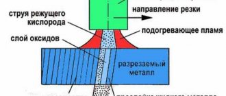
Rice. .2. Scheme of milling a trib tooth in three transitions, (a, b, c);
1
- cutter;
2
- detail
Fig.3. Installing cutters on a mandrel when milling in three transitions
…………………………………………………………………………………………………………………………………….
Fig. 5 Shaving with a rack shaver (Fig. 9, a 1 - detail; 2 - shaver), disk shaver
Fig.5. Disc shaver
…………………………………………………………………………………………………………………………………….
Fig.6 Scheme of grinding teeth. 1- lap, 2- detail
The meaning of shaving
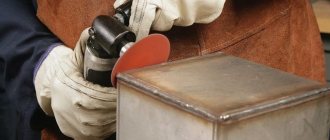
The most important meaning of shaving is scraping off the excess top layer of metal from the workpiece, namely, from steel gears. The processing tool is made of high-speed steel, so shaving is done quickly.
Being in contact with the wheel being processed, the parts of the shaver pass along the sides of its cutters, thus removing an unnecessary layer of metal.
The edges of the shaver are formed using transverse grooves located on the working part of the tool, thanks to which shaving occurs. When mounted on a machine, the movement of the teeth of the shaver and the wheel being processed is obtained; the movement depends on the inclination, which has an angle. The efficiency of shaving is the sum or difference in the angles of inclination of the part. The axes of the workpiece and the tool are placed at the required angles and can be directed both in the same directions and in opposite directions, which determines which sign (“+” or “-”, respectively) will be placed in front of the value of the characteristic under consideration.
Shaving process technology
Shearing of gears is the removal of excess metal by cutting when mating the cutting tool with the gear being processed. Thus, during the processing process, a gear pair is formed, rotated by the machine drive. Thin strips of metal are removed in the contact area. The direction of metal removal depends on the method of feeding the shaver.
On high-precision machines, the possibility of oscillating movement of the cutting tool is realized. The most effective frequency is considered to be in the range of 20–100 Hz. This allows processing to be done in one pass and reduces surface roughness.
The calculation of the allowance is performed during the manufacturing process of the gear. The initial data are the module, gear diameter, as well as the required accuracy class of the finished product.
Carrying out
When performing shaving, a specialist positions the shaver and wheel in such a way that their axes twist at the required angle (from 10 to 15 degrees). With this process, the movement from the machine is transferred to the shaver, and at this time it rotates the product. Calibration of the cutters occurs along the line, which is the smallest distance between the axes of the shaver and the wheel. For calibration to take place over the entire area of the teeth, the product must continuously move along a given path. To comply with this condition, several types of feed motion are transmitted to the cutting tool:
- transverse (perpendicular to the axis of the product);
- longitudinal;
- tangential (perpendicular to the axis of the shaver itself);
- diagonal (at the required angle to the axis of the product).
If the shaver moves in a direction coinciding with the axis of the product and the magnitude of such a move is the same as the width of the teeth, then this is a longitudinal feed. The line under such conditions is stationary. Shaving in this case will be performed using repeating sections of the cutting edge of the tool, so the teeth of the shaver wear out gradually and evenly.
Transverse, diagonal and tangential feeds also ensure uniform wear of the teeth, make it possible to shorten the stroke of the tool and draw its cutting teeth over almost the entire width of their working surface.
If the shaver is given an oscillating movement, then it will be possible to perform shaving with better results. This movement should have a frequency of 20 to 100 Hz; only under such conditions will shaving be more effective than usual. This method makes it possible to obtain the following characteristics:
- reduction in roughness by 0.3 - 0.6 microns, this result is usually obtained only by grinding;
- intensification;
- reduction of time.
Disadvantages of the method
The disadvantage of this process is the absence of a rigid kinematic connection between the shaver and the wheel being processed, which is why an error accumulates at the next step.
The next disadvantage is the dependence of the processing accuracy on the properties of gear cutting and allowance.
The method of processing incisors with edge shavers is becoming increasingly popular. In this procedure, there is a rigid kinematic connection between the wheel and the cutting tool. For processing, a pair of shaver is used, each of which processes the side of the wheel cutter assigned to it in the same direction of movement as in rolling with feed.
Worm and tight shaver
Metal gears of low accuracy class or equipped with barrel-shaped teeth are finished with a tight-fitting shaver.
Tight-fitting shavers
A form-fitting cutting tool differs from a conventional one in the type of contact between the teeth of the elements. During shaver processing, adhesion to the wheel is linear and occurs over the entire surface. The intersection of the axes at the point is not required to obtain the result; longitudinal feed is not used.
Tight-fitting shavers are used:
Tight-fitting shavers
- to reduce machine processing time;
- formation of a barrel-shaped surface of the teeth.
It is taken into account that the accuracy of shaving of wheels processed with a tight-fitting shaver is lower than the accuracy achieved with a disk tool. Errors arise due to the shape of the shaver, the side cutting surface of which is concave. Involute (convex) cutting surfaces provide greater calibration accuracy.
Worm shavers
The operating principle of a worm gear is based on the physics of a worm gear.
The worm, as a cutting tool, is equipped with sparse small teeth with a notch on the side surface.
The rotation of the worm cutter is carried out:
Worm shavers - diagram and description
- In a circular direction, a gap is formed between the helical side surface of the cutting tool and the workpiece.
- Radial direction. In this case, there is no side clearance, the edges of the workpiece and the tool fit tightly to each other.
When rotating in a circular manner, the center distance between the worm and the wheel is maintained by constant braking of the wheel. The size of the worm turns depends on the processing allowances.
The working movement in the radial direction occurs by bringing the wheel axes and cutting edges closer together. The size of the notch turns is equal to the size of the depressions between the teeth of the part.
Gear shearing machine 5702A
For a more specific understanding of the operating principles of specialized equipment for shaving, let’s look at the example of the operation of the machine – 5702A. This model is most common in mass and batch production applications.
Main characteristics:
- maximum module of the processed product – 6 mm;
- engine power is 2.8 kW;
- maximum gear section – 200 mm;
- travel speed range from 78 to 395 rpm.
The model has a hydraulic feed drive of the radial type and an electromechanical drive of the axial type.
The work is provided by an electric motor. The shaver itself has 10 stages, which are adjusted using gears.
Using the right headstock of the unit, you can clamp the workpiece in working centers, and the head of the working tool makes it possible to adjust the engagement angle. It can rotate in both directions, the rotation angle can be from 0 to 35 degrees.
Due to the motor, whose power is 0.6 kW, axial feeds are performed. Thanks to the vertical movement of the console, beam-type feeds occur.
The versatility of this equipment lies in the fact that it can work with barrel-shaped cutters, which is why it is in greatest demand among other models.
Types and shape of shaver
In the process of processing gears, the following types of shaver are used:
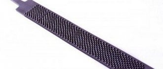
- Rack and pinion. Purpose – shaving of gears with straight and helical teeth. It looks like an oblong strip with removable toothed notches. This type is not characterized by high processing accuracy and therefore is not particularly popular.
- Disc shaver. It is a disc wheel made of high-speed steel. Each tooth has transverse grooves that form cutting edges. In addition, they perform the function of removing metal processing by-products.
- Tight-fitting. For shaving barrel-shaped teeth.
- Worm. A tool for processing the corresponding transfers.
Let's look at the last two types in more detail.
Tight-fitting shavers
This is a cutting tool that does not require longitudinal feed, and processing is performed along a linear engagement surface.
The use of these shavers allows you to reduce processing time. Compared to disk-type devices, the accuracy of tight-fitting shavers is slightly lower. As a result of exposure, you can get a barrel-shaped tooth.
The main difference from the standard tool is the effect on the contact plane. The direction of movement is in the shape of a concave line rather than a straight line. Due to this, teeth of a specific shape are obtained.
Application area
Shewing is a very effective and also quite common technology that is often used in modern industry. In Russia, this technology has been used since 1936.
This method is in demand in various fields, but most of all it is used in automotive production, because gearboxes and worm gears are made from parts that have been calibrated.
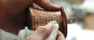
The wire also undergoes shaving treatment, thereby increasing its elasticity and removing excess impurities, improving the composition of the product.
Where and why is shaving used?
The technology does not have a rich history. It was invented in the 30s of the last century in the USA by National Broach. Since 1936, shaving of gear wheels has been tested at the Moscow Automobile Plant named after Stalin.
The technology of shaving gears is a popular procedure in modern production. In the automotive industry, gears are used in gearboxes, axle reducers, transfer cases and other components. In addition, shaving is used in other industries where high demands are placed on the accuracy of gearing.
The result of the treatment is a geometrically correct shape of the teeth, the surface of which acquires mechanical strength and elasticity. This improves transmission accuracy and reduces the noise level during gear operation.
The technical characteristics of some alloys do not allow finishing by grinding. In this case, the workpieces are subjected to shaving.
Shaving treatment is rarely used as an alternative to chemical cleaning of metal, since shaving is a less dangerous and labor-intensive procedure.
Mechanical removal of excess chips has the following goals:
- straightening the side faces of spur and helical gears;
- increasing the accuracy of the product by 2-3 classes;
- improving performance characteristics.
In addition to gears, wire products are subjected to shaving. The treatment process removes foreign surface deposits, improving the quality of the material.
The technology is used for processing the following metals and alloys:
- various types of steel, including spring steel;
- copper;
- brass;
- bronze;
- aluminum and alloys based on it;
- zinc